EP0126508B2 - Method of seam welding a metal tube formed from a folded strip - Google Patents
Method of seam welding a metal tube formed from a folded strip Download PDFInfo
- Publication number
- EP0126508B2 EP0126508B2 EP84200661A EP84200661A EP0126508B2 EP 0126508 B2 EP0126508 B2 EP 0126508B2 EP 84200661 A EP84200661 A EP 84200661A EP 84200661 A EP84200661 A EP 84200661A EP 0126508 B2 EP0126508 B2 EP 0126508B2
- Authority
- EP
- European Patent Office
- Prior art keywords
- welding
- tube
- steady state
- welded seam
- seam
- Prior art date
- Legal status (The legal status is an assumption and is not a legal conclusion. Google has not performed a legal analysis and makes no representation as to the accuracy of the status listed.)
- Expired - Lifetime
Links
Images


Classifications
-
- B—PERFORMING OPERATIONS; TRANSPORTING
- B23—MACHINE TOOLS; METAL-WORKING NOT OTHERWISE PROVIDED FOR
- B23K—SOLDERING OR UNSOLDERING; WELDING; CLADDING OR PLATING BY SOLDERING OR WELDING; CUTTING BY APPLYING HEAT LOCALLY, e.g. FLAME CUTTING; WORKING BY LASER BEAM
- B23K9/00—Arc welding or cutting
- B23K9/02—Seam welding; Backing means; Inserts
- B23K9/025—Seam welding; Backing means; Inserts for rectilinear seams
- B23K9/0253—Seam welding; Backing means; Inserts for rectilinear seams for the longitudinal seam of tubes
-
- B—PERFORMING OPERATIONS; TRANSPORTING
- B23—MACHINE TOOLS; METAL-WORKING NOT OTHERWISE PROVIDED FOR
- B23K—SOLDERING OR UNSOLDERING; WELDING; CLADDING OR PLATING BY SOLDERING OR WELDING; CUTTING BY APPLYING HEAT LOCALLY, e.g. FLAME CUTTING; WORKING BY LASER BEAM
- B23K31/00—Processes relevant to this subclass, specially adapted for particular articles or purposes, but not covered by only one of the preceding main groups
- B23K31/02—Processes relevant to this subclass, specially adapted for particular articles or purposes, but not covered by only one of the preceding main groups relating to soldering or welding
- B23K31/027—Making tubes with soldering or welding
Definitions
- This invention relates to a method of seam welding a metal tube formed from a folded strip.
- the manufacturing process of welded tubes obtained by shaping a strip does not involve any special problems as to stop and restart of the productive run if the thickness of the workpieces exceeds 0.8 mm to 0.9 mm as an average.
- the lengths usually required in the trade from such installations do not exceed, as a rule, ten metres.
- the installations for the production of thinwalled tubes, for example for making hypodermic needles are capable of continuously producing the article with the limitations inherent in the welding electrodes or, anyway, in the correct operation of the welding torch.
- An objective of the present invention is to provide a method of seam welding a metal formed from a folded strip, which makes it possible to produce thin-walled tubes having high length. Having this objective in view, according to the present invention, it has been envisaged to provide a method of seam welding a metal tube formed from a folded strip through welding means, the method comprising the step of moving, during a steady state stage, the tube with respect to the welding means to form a continuous longitudinal welded seam on the tube, the step of stopping, during a stop stage, the tube, and the step of moving again, during a restart stage, the tube with respect to the welding means, shifting the welding means from an inoperative position along the previously formed welded seam to an operative position upon the welded seam end, to continue the welded seam, characterized in that during said stop stage the welding means are shifted along the welded seam from said operative position to said inoperative position overwelding the previously welded seam and theirwelding power is gradually decreased from the steady state value to a zero value, and during said restart stage the welding means
- a blade 20 is provided, to guide and to position the electric wire 13 in the interior of the folded strip 16, said blade 20 being equipped with feeding means 21 which are adapted to introduce a protective gas (such as argon) into the interior of the shaped tube ( Figures 2, 3).
- the welding member 19, the blade 20, the couples of rollers 15 and 18 and the cooling tub 26 are secured to the slide 22, which is equipped with driving means 23 which drive the slide on guideways 24 along a direction which is parallel to that of the tube 17, the forward motion being that of the arrow 25 and the backward motion taking place in the reverse direction.
- the rolled section as obtained from the strip 16 and enclosing in its interior the wire 13, is brought into registry with the couple of shaping rollers 18.
- the blade 20 is slipped between the strip edges, which are still spaced apart, and acts so as to shift by a few millimetres the wire 13 away of the wall of the strip 16 to be welded, so as not to damage the wire, protective gas being meanwhile introduced as fed by the means 21.
- the welding current is raised up to the steady state value (as symbolized by 0 to 1) and the slide 22, driven by the driving means 23, sets the means 19 into the position where the welding operation begins.
- the cable 17 so sheathed is fed forward along the direction of the arrow 25 as propelled by the shaping rollers of a shaping machine (not shown), while the welding means 19 are fed backwards and moved in a direction against that of the arrow 25.
- the machine 10 As the welding current has attained its maximum preset ampere value (1), the machine 10 is in its "steady” state, the cable 17 is being continually shaped and the carriage 22 holds the welding means in its operative position ( Figure 2).
- the cable 17 is immersed in the tub 26, an entity with the carriage 22, and is submerged for at least one half of its thickness so as to be cooled.
- the cable 17 is stopped, the carriage 22, which carries the blade 20, the welding means 19, the couples of rollers 15 and 18 and the cooling tub 26, is carried from the area 1 to 0 and the already welded seam 11 is travelled over again, while, simultaneously, the welding current ampere is gradually decreased from the value 1 to the value 0 ( Figure 3).
- CYCLE STOP The entire stage as now described is called "CYCLE STOP" and makes it possible to effect a stoppage in the production of the cable 17 without piercing the wall of the tube 12 or jeopardizing the integrity of the wire 13.
- a cable 17 so constructed is then subjected, as a rule, to extrusion, so as to immobilize the wire or other article therein and, if necessary, also to correct the roundness of the tube.
- the longitudinal welding operation can be effected both as a butt-welding or with a partial edge overlapping, or according to any other suitable technological operations.
Abstract
Description
- This invention relates to a method of seam welding a metal tube formed from a folded strip. The manufacturing process of welded tubes obtained by shaping a strip does not involve any special problems as to stop and restart of the productive run if the thickness of the workpieces exceeds 0.8 mm to 0.9 mm as an average. In addition, the lengths usually required in the trade from such installations do not exceed, as a rule, ten metres. The installations for the production of thinwalled tubes, for example for making hypodermic needles, are capable of continuously producing the article with the limitations inherent in the welding electrodes or, anyway, in the correct operation of the welding torch.
- With the TIG process, such limitation is due to the evaporation of thorium as alloyed in the electrode, the formation of the melted drop and the resultant stop of the welding bath. Usually, this occurs after 2 or 3 hours of continuous operation.
- With the plasma welding process, the limitation is to be attributed, instead, to the formation of carbon deposits (between the electrode and the clamps) which actually impair the processing continuity. This usually takes places after 6-8 hours of continuous operation (a working shift).
- In the installations mentioned above, the stoppage of the welding run together with the impossibility of restarting same involves the acceptance of the as- produced length and the consequential start of another production cycle.
- It has been proposed (AT-BB-277 719) a method of seam welding a metal tube wherein, during a restarting stage, an auxiliary electrode is interposed between the welding electrode and the tube in order to avoid weld faults.
- This method, however, is not practical when thin tubes are to be welded. In fact, as known, the space between the welding electrode and the tube must be substantially equal to the thickness of the tube ; it would be very difficult to interpose an auxiliary electrode in such a small space.
- An objective of the present invention is to provide a method of seam welding a metal formed from a folded strip, which makes it possible to produce thin-walled tubes having high length. Having this objective in view, according to the present invention, it has been envisaged to provide a method of seam welding a metal tube formed from a folded strip through welding means, the method comprising the step of moving, during a steady state stage, the tube with respect to the welding means to form a continuous longitudinal welded seam on the tube, the step of stopping, during a stop stage, the tube, and the step of moving again, during a restart stage, the tube with respect to the welding means, shifting the welding means from an inoperative position along the previously formed welded seam to an operative position upon the welded seam end, to continue the welded seam, characterized in that during said stop stage the welding means are shifted along the welded seam from said operative position to said inoperative position overwelding the previously welded seam and theirwelding power is gradually decreased from the steady state value to a zero value, and during said restart stage the welding means are operated starting from said inoperative position, overwelding the previously welded seam, and their welding power is gradually increased from the zero value to the steady stage value, the welding means being shifted together with means which shape and cool the tube.
- The structural and functional features and the advantages of the method according to the invention, will be more clearly understood from the ensuing nonlimiting description, aided by the accompanying drawings, wherein :
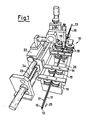
- Figure 1 is a diagrammatical perspective view of an apparatus used for performing a method according to the invention.
- Figures 2 and 3 are perspective views of a single detail of the welding area of said apparatus in different working stages, and
- Figure 4 is a diagram of the several working stages of the aforesaid method according to the invention.
- Figure 1 shows an automatic machine, 10, for welding a
longitudinal seam 11 in a process for producing thin-walled tubes 12 as obtained from astrip 16, and more particularly adapted to contain, for example,electric wire 13. - A
frame 14, rigidly connected to amovable slide 22, bears a set of couples ofrollers 15, of the pulley type, for holding thecable 17, so shaped and welded, within acooling tub 26. A couple ofshaping rollers 18, at the inlet end of themachine 10, completes the shaping of thestrip 16 prior to carrying out the long itu-dinal seam 11, that which is effected by a specially providedmember 19, to be selected consistently with the process used. Upstream of the couple of theshaping rollers 18 and thewelding member 19, ablade 20 is provided, to guide and to position theelectric wire 13 in the interior of the foldedstrip 16, saidblade 20 being equipped withfeeding means 21 which are adapted to introduce a protective gas (such as argon) into the interior of the shaped tube (Figures 2, 3). Thewelding member 19, theblade 20, the couples ofrollers cooling tub 26 are secured to theslide 22, which is equipped withdriving means 23 which drive the slide onguideways 24 along a direction which is parallel to that of thetube 17, the forward motion being that of thearrow 25 and the backward motion taking place in the reverse direction. - The operation of an apparatus so conceived is diagrammatically set forth in the scheme of Figure 4, namely :
- The rolled section, as obtained from the
strip 16 and enclosing in its interior thewire 13, is brought into registry with the couple ofshaping rollers 18. - In said position, the
blade 20 is slipped between the strip edges, which are still spaced apart, and acts so as to shift by a few millimetres thewire 13 away of the wall of thestrip 16 to be welded, so as not to damage the wire, protective gas being meanwhile introduced as fed by themeans 21. - Once the folded
strip 16 and thewire 13 are enclosed therein between theshaping rollers 18, thewelding member 19 is started. - According to a programme which is a function of the material to be processed, the welding current is raised up to the steady state value (as symbolized by 0 to 1) and the
slide 22, driven by the driving means 23, sets themeans 19 into the position where the welding operation begins. During this stage, called the "CYCLE START", thecable 17 so sheathed is fed forward along the direction of thearrow 25 as propelled by the shaping rollers of a shaping machine (not shown), while the welding means 19 are fed backwards and moved in a direction against that of thearrow 25. As the welding current has attained its maximum preset ampere value (1), themachine 10 is in its "steady" state, thecable 17 is being continually shaped and thecarriage 22 holds the welding means in its operative position (Figure 2). Past the welding means 19, thecable 17 is immersed in thetub 26, an entity with thecarriage 22, and is submerged for at least one half of its thickness so as to be cooled. - It is now necessary to act so as to stop welding, such as for adjustments, control, or a stoppage due to the end of a workshop shift or for any other reason whatsoever
- To obtain this, the
cable 17 is stopped, thecarriage 22, which carries theblade 20, the welding means 19, the couples ofrollers cooling tub 26, is carried from thearea 1 to 0 and the alreadywelded seam 11 is travelled over again, while, simultaneously, the welding current ampere is gradually decreased from thevalue 1 to the value 0 (Figure 3). - The entire stage as now described is called "CYCLE STOP" and makes it possible to effect a stoppage in the production of the
cable 17 without piercing the wall of thetube 12 or jeopardizing the integrity of thewire 13. - During a "CYCLE RESTART" stage, the operations performed during the "CYCLE START" tage are virtually repeated as such, that is, the
carriage 22 brings thewelding means 19, theroller couples cooling tub 26 from the position 0 to theposition 1 while the welding current ampere is gradually raised from the value 0 to the steady state value, as indicated by thereference numeral 1 herein. - During the latter stage, however, the welding means 19 and the couples of shaping
rollers 18 travel over an already welded section once again, whereby thelongitudinal welding seam 11 is overcast and its continuity and integrity are thus warranted while the internally enclosedwire 13 remains unaffected - It is apparent that such a welding process and machine can be used with advantage also in those cases in which the
tube 12 is to contain in its interior, once it has been welded, optical fibres, wire bundles or other particular articles, so as to obtain cables which are outstandingly resistant, forexample, to heat and corrosion. - A
cable 17 so constructed is then subjected, as a rule, to extrusion, so as to immobilize the wire or other article therein and, if necessary, also to correct the roundness of the tube. The longitudinal welding operation can be effected both as a butt-welding or with a partial edge overlapping, or according to any other suitable technological operations.
Claims (1)
Priority Applications (1)
| Application Number | Priority Date | Filing Date | Title |
|---|---|---|---|
| AT84200661T ATE30687T1 (en) | 1983-05-13 | 1984-05-08 | PROCESS FOR SEAM WELDING PIPES FROM A CURVED METAL STRIP. |
Applications Claiming Priority (2)
| Application Number | Priority Date | Filing Date | Title |
|---|---|---|---|
| IT2109583 | 1983-05-13 | ||
| IT21095/83A IT1163368B (en) | 1983-05-13 | 1983-05-13 | METHOD AND AUTOMATIC EQUIPMENT FOR THE RECOVERY OF LONGITUDINAL WELDING IN THE CONSTRUCTION OF THIN WALL TUBES OBTAINED FROM PROFILED TAPE, SUITABLE FOR COATING CONDUCTORS |
Publications (3)
| Publication Number | Publication Date |
|---|---|
| EP0126508A1 EP0126508A1 (en) | 1984-11-28 |
| EP0126508B1 EP0126508B1 (en) | 1987-11-11 |
| EP0126508B2 true EP0126508B2 (en) | 1991-03-20 |
Family
ID=11176659
Family Applications (1)
| Application Number | Title | Priority Date | Filing Date |
|---|---|---|---|
| EP84200661A Expired - Lifetime EP0126508B2 (en) | 1983-05-13 | 1984-05-08 | Method of seam welding a metal tube formed from a folded strip |
Country Status (7)
| Country | Link |
|---|---|
| US (1) | US4626644A (en) |
| EP (1) | EP0126508B2 (en) |
| JP (1) | JPS6046869A (en) |
| AT (1) | ATE30687T1 (en) |
| CA (1) | CA1224649A (en) |
| DE (1) | DE3467314D1 (en) |
| IT (1) | IT1163368B (en) |
Families Citing this family (8)
| Publication number | Priority date | Publication date | Assignee | Title |
|---|---|---|---|---|
| US4793048A (en) * | 1987-02-18 | 1988-12-27 | Nippon Steel Corporation | Method for passing optical fibers through tubular products by vibrating the tubular products |
| JPH07115177B2 (en) * | 1988-07-14 | 1995-12-13 | 昭和電線電纜株式会社 | Conduit tube manufacturing equipment |
| JP2921903B2 (en) * | 1990-03-02 | 1999-07-19 | 株式会社日立製作所 | Welding robot controller |
| US5346116A (en) * | 1993-06-24 | 1994-09-13 | Hall Jr Bertie F | Machine for forming a metal strip into a tubular form having a stop-restart displacement mechanism |
| JP3239671B2 (en) * | 1995-03-08 | 2001-12-17 | 松下電器産業株式会社 | Film heaters, heated seats, evaporation boats and heating furnaces |
| US20100051586A1 (en) * | 2008-05-06 | 2010-03-04 | Apparent Technologies, Inc. | Orbital welding system and methods of operations |
| CN105478525B (en) * | 2016-01-06 | 2017-10-31 | 河北华通线缆集团股份有限公司 | A kind of manufacture method for the coiled tubing for including logging cable |
| DE102016216170A1 (en) * | 2016-08-29 | 2018-03-01 | Gökhan Biyikli | WELDING METHOD AND WELDING DEVICE |
Family Cites Families (7)
| Publication number | Priority date | Publication date | Assignee | Title |
|---|---|---|---|---|
| US2796508A (en) * | 1952-07-25 | 1957-06-18 | Aluminum Supply Co | Method for producing non-ferrous continuous weld tubing |
| US3360177A (en) * | 1964-04-16 | 1967-12-26 | Sandvikens Jernverks Ab | Tube welding apparatus |
| GB1045104A (en) * | 1965-06-25 | 1966-10-05 | Standard Telephones Cables Ltd | Improvements in or relating to seam welding of tubes |
| US3555239A (en) * | 1966-11-16 | 1971-01-12 | William J Kerth | Welding machine with digital pulse control |
| FR1599054A (en) * | 1968-11-20 | 1970-07-15 | ||
| FR2093378A5 (en) * | 1970-06-12 | 1972-01-28 | Tubest Sa | |
| US4143801A (en) * | 1977-02-09 | 1979-03-13 | Michael P. Breston | Multiple welding head system for fabricating pipe |
-
1983
- 1983-05-13 IT IT21095/83A patent/IT1163368B/en active
-
1984
- 1984-05-08 DE DE8484200661T patent/DE3467314D1/en not_active Expired
- 1984-05-08 EP EP84200661A patent/EP0126508B2/en not_active Expired - Lifetime
- 1984-05-08 AT AT84200661T patent/ATE30687T1/en not_active IP Right Cessation
- 1984-05-11 US US06/609,133 patent/US4626644A/en not_active Expired - Fee Related
- 1984-05-11 CA CA000454159A patent/CA1224649A/en not_active Expired
- 1984-05-14 JP JP59094754A patent/JPS6046869A/en active Pending
Also Published As
| Publication number | Publication date |
|---|---|
| DE3467314D1 (en) | 1987-12-17 |
| EP0126508B1 (en) | 1987-11-11 |
| US4626644A (en) | 1986-12-02 |
| IT8321095A1 (en) | 1984-11-13 |
| CA1224649A (en) | 1987-07-28 |
| JPS6046869A (en) | 1985-03-13 |
| EP0126508A1 (en) | 1984-11-28 |
| IT1163368B (en) | 1987-04-08 |
| ATE30687T1 (en) | 1987-11-15 |
| IT8321095A0 (en) | 1983-05-13 |
Similar Documents
| Publication | Publication Date | Title |
|---|---|---|
| EP0126508B2 (en) | Method of seam welding a metal tube formed from a folded strip | |
| SU1715200A3 (en) | Method and apparatus for making light conducting cable | |
| JPH0253528A (en) | Wire connecting method for wire electric discharge machine | |
| US10500660B2 (en) | Wire electric discharge machine provided with disconnection repairing unit | |
| JPS6040601A (en) | Method and equipment for continuously hot rolling billet | |
| KR890003803B1 (en) | Multistage wire drawing apparatus | |
| GB2062527A (en) | Wire threading in wire-cut electroerosion machining processes | |
| US4850522A (en) | Steel strip splicing station | |
| CN111922243A (en) | PVC pipeline recovery processing device | |
| US4291644A (en) | Apparatus for fabricating composite metal wire | |
| CN113084452A (en) | Production method of large-diameter thick-wall steel pipe | |
| US5618453A (en) | Combined cutting and welding method and relative apparatus for manufacturing structural sheet metal products | |
| JP5488945B1 (en) | Interlock tube manufacturing method and manufacturing apparatus thereof | |
| US4339654A (en) | Methods for the manufacture of heat exchanger panels | |
| CN1113464A (en) | Apparatus for surface cutting | |
| US3245139A (en) | Method of repairing corrugated tubing about a core | |
| CN215824504U (en) | Chain conveying mechanism for full-automatic flash butt welding machine | |
| CN116038118B (en) | Automatic wire rod ring waist line winding robot and operation method thereof | |
| JPH0698487B2 (en) | Joining method for band steel for ERW pipe | |
| JP5163600B2 (en) | Circumferential welding method for fixed pipe | |
| KR200205249Y1 (en) | Welded Surface Processing Equipment | |
| JP3497235B2 (en) | Strip edge cutting beveling machine | |
| CN112958994A (en) | Heavy-calibre thick wall steel pipe welding equipment | |
| SU1523209A2 (en) | Method of producing longitudinal tubes | |
| JPS61260928A (en) | Double-wire wire-cut electric discharge machine |
Legal Events
| Date | Code | Title | Description |
|---|---|---|---|
| PUAI | Public reference made under article 153(3) epc to a published international application that has entered the european phase |
Free format text: ORIGINAL CODE: 0009012 |
|
| AK | Designated contracting states |
Designated state(s): AT BE CH DE FR GB LI LU NL SE |
|
| 17P | Request for examination filed |
Effective date: 19850320 |
|
| 17Q | First examination report despatched |
Effective date: 19860528 |
|
| GRAA | (expected) grant |
Free format text: ORIGINAL CODE: 0009210 |
|
| AK | Designated contracting states |
Kind code of ref document: B1 Designated state(s): AT BE CH DE FR GB LI LU NL SE |
|
| PG25 | Lapsed in a contracting state [announced via postgrant information from national office to epo] |
Ref country code: LI Effective date: 19871111 Ref country code: CH Effective date: 19871111 Ref country code: AT Effective date: 19871111 |
|
| REF | Corresponds to: |
Ref document number: 30687 Country of ref document: AT Date of ref document: 19871115 Kind code of ref document: T |
|
| PG25 | Lapsed in a contracting state [announced via postgrant information from national office to epo] |
Ref country code: SE Effective date: 19871130 |
|
| REF | Corresponds to: |
Ref document number: 3467314 Country of ref document: DE Date of ref document: 19871217 |
|
| ET | Fr: translation filed | ||
| PLBI | Opposition filed |
Free format text: ORIGINAL CODE: 0009260 |
|
| REG | Reference to a national code |
Ref country code: CH Ref legal event code: PL |
|
| 26 | Opposition filed |
Opponent name: KABELMETAL ELECTRO GMBH Effective date: 19880213 |
|
| NLR1 | Nl: opposition has been filed with the epo |
Opponent name: KABELMETAL ELECTRO GMBH |
|
| PG25 | Lapsed in a contracting state [announced via postgrant information from national office to epo] |
Ref country code: LU Free format text: LAPSE BECAUSE OF NON-PAYMENT OF DUE FEES Effective date: 19880531 |
|
| PUAH | Patent maintained in amended form |
Free format text: ORIGINAL CODE: 0009272 |
|
| STAA | Information on the status of an ep patent application or granted ep patent |
Free format text: STATUS: PATENT MAINTAINED AS AMENDED |
|
| 27A | Patent maintained in amended form |
Effective date: 19910320 |
|
| AK | Designated contracting states |
Kind code of ref document: B2 Designated state(s): AT BE CH DE FR GB LI LU NL SE |
|
| REG | Reference to a national code |
Ref country code: CH Ref legal event code: AEN |
|
| NLR2 | Nl: decision of opposition | ||
| NLR3 | Nl: receipt of modified translations in the netherlands language after an opposition procedure | ||
| ET3 | Fr: translation filed ** decision concerning opposition | ||
| PGFP | Annual fee paid to national office [announced via postgrant information from national office to epo] |
Ref country code: GB Payment date: 19930430 Year of fee payment: 10 |
|
| PGFP | Annual fee paid to national office [announced via postgrant information from national office to epo] |
Ref country code: BE Payment date: 19930504 Year of fee payment: 10 |
|
| PGFP | Annual fee paid to national office [announced via postgrant information from national office to epo] |
Ref country code: NL Payment date: 19930531 Year of fee payment: 10 |
|
| PG25 | Lapsed in a contracting state [announced via postgrant information from national office to epo] |
Ref country code: GB Effective date: 19940508 |
|
| PG25 | Lapsed in a contracting state [announced via postgrant information from national office to epo] |
Ref country code: BE Effective date: 19940531 |
|
| BERE | Be: lapsed |
Owner name: CISE-CENTRO INFORMAZIONI STUDI ESPERIENZE S.P.A. Effective date: 19940531 |
|
| PG25 | Lapsed in a contracting state [announced via postgrant information from national office to epo] |
Ref country code: NL Effective date: 19941201 |
|
| GBPC | Gb: european patent ceased through non-payment of renewal fee |
Effective date: 19940508 |
|
| NLV4 | Nl: lapsed or anulled due to non-payment of the annual fee | ||
| PGFP | Annual fee paid to national office [announced via postgrant information from national office to epo] |
Ref country code: FR Payment date: 19970515 Year of fee payment: 14 |
|
| PGFP | Annual fee paid to national office [announced via postgrant information from national office to epo] |
Ref country code: DE Payment date: 19970516 Year of fee payment: 14 |
|
| PG25 | Lapsed in a contracting state [announced via postgrant information from national office to epo] |
Ref country code: FR Free format text: LAPSE BECAUSE OF NON-PAYMENT OF DUE FEES Effective date: 19980531 |
|
| PG25 | Lapsed in a contracting state [announced via postgrant information from national office to epo] |
Ref country code: DE Free format text: LAPSE BECAUSE OF NON-PAYMENT OF DUE FEES Effective date: 19990302 |
|
| REG | Reference to a national code |
Ref country code: FR Ref legal event code: ST |