EP0126321B1 - Demand valve for a breathing apparatus - Google Patents
Demand valve for a breathing apparatus Download PDFInfo
- Publication number
- EP0126321B1 EP0126321B1 EP84104609A EP84104609A EP0126321B1 EP 0126321 B1 EP0126321 B1 EP 0126321B1 EP 84104609 A EP84104609 A EP 84104609A EP 84104609 A EP84104609 A EP 84104609A EP 0126321 B1 EP0126321 B1 EP 0126321B1
- Authority
- EP
- European Patent Office
- Prior art keywords
- handle
- wall
- cover
- piston
- configuration
- Prior art date
- Legal status (The legal status is an assumption and is not a legal conclusion. Google has not performed a legal analysis and makes no representation as to the accuracy of the status listed.)
- Expired
Links
- 230000029058 respiratory gaseous exchange Effects 0.000 title claims description 4
- 239000012528 membrane Substances 0.000 claims description 23
- 230000000007 visual effect Effects 0.000 claims description 3
- 238000006243 chemical reaction Methods 0.000 description 2
- 230000008878 coupling Effects 0.000 description 2
- 238000010168 coupling process Methods 0.000 description 2
- 238000005859 coupling reaction Methods 0.000 description 2
- 238000004891 communication Methods 0.000 description 1
- 238000006073 displacement reaction Methods 0.000 description 1
- 230000000694 effects Effects 0.000 description 1
- 238000005516 engineering process Methods 0.000 description 1
- 239000007924 injection Substances 0.000 description 1
- 238000002347 injection Methods 0.000 description 1
- 238000012986 modification Methods 0.000 description 1
- 230000004048 modification Effects 0.000 description 1
- 230000002093 peripheral effect Effects 0.000 description 1
- 238000009877 rendering Methods 0.000 description 1
- 230000000284 resting effect Effects 0.000 description 1
- 239000012815 thermoplastic material Substances 0.000 description 1
Images


Classifications
-
- A—HUMAN NECESSITIES
- A61—MEDICAL OR VETERINARY SCIENCE; HYGIENE
- A61M—DEVICES FOR INTRODUCING MEDIA INTO, OR ONTO, THE BODY; DEVICES FOR TRANSDUCING BODY MEDIA OR FOR TAKING MEDIA FROM THE BODY; DEVICES FOR PRODUCING OR ENDING SLEEP OR STUPOR
- A61M16/00—Devices for influencing the respiratory system of patients by gas treatment, e.g. ventilators; Tracheal tubes
- A61M16/20—Valves specially adapted to medical respiratory devices
-
- A—HUMAN NECESSITIES
- A61—MEDICAL OR VETERINARY SCIENCE; HYGIENE
- A61M—DEVICES FOR INTRODUCING MEDIA INTO, OR ONTO, THE BODY; DEVICES FOR TRANSDUCING BODY MEDIA OR FOR TAKING MEDIA FROM THE BODY; DEVICES FOR PRODUCING OR ENDING SLEEP OR STUPOR
- A61M16/00—Devices for influencing the respiratory system of patients by gas treatment, e.g. ventilators; Tracheal tubes
- A61M16/20—Valves specially adapted to medical respiratory devices
- A61M16/201—Controlled valves
- A61M16/206—Capsule valves, e.g. mushroom, membrane valves
-
- Y—GENERAL TAGGING OF NEW TECHNOLOGICAL DEVELOPMENTS; GENERAL TAGGING OF CROSS-SECTIONAL TECHNOLOGIES SPANNING OVER SEVERAL SECTIONS OF THE IPC; TECHNICAL SUBJECTS COVERED BY FORMER USPC CROSS-REFERENCE ART COLLECTIONS [XRACs] AND DIGESTS
- Y10—TECHNICAL SUBJECTS COVERED BY FORMER USPC
- Y10S—TECHNICAL SUBJECTS COVERED BY FORMER USPC CROSS-REFERENCE ART COLLECTIONS [XRACs] AND DIGESTS
- Y10S137/00—Fluid handling
- Y10S137/908—Respirator control
-
- Y—GENERAL TAGGING OF NEW TECHNOLOGICAL DEVELOPMENTS; GENERAL TAGGING OF CROSS-SECTIONAL TECHNOLOGIES SPANNING OVER SEVERAL SECTIONS OF THE IPC; TECHNICAL SUBJECTS COVERED BY FORMER USPC CROSS-REFERENCE ART COLLECTIONS [XRACs] AND DIGESTS
- Y10—TECHNICAL SUBJECTS COVERED BY FORMER USPC
- Y10T—TECHNICAL SUBJECTS COVERED BY FORMER US CLASSIFICATION
- Y10T137/00—Fluid handling
- Y10T137/7722—Line condition change responsive valves
- Y10T137/7781—With separate connected fluid reactor surface
Definitions
- the present invention refers to a demand valve for introducing breathable air into a self-breathing apparatus (compressed air breathing apparatus)-in particular, inside the mask of the self-breathing apparatus itself.
- the distributor along with which the commutator device of the invention can be utilized, is of the type according to GB-A-1.401.613 that comprises a transducer for controlling the movement of a valve element for feeding predetermined quantities of air into a chamber of the distributor itself, following a pressure variation that is verified in said chamber.
- the above-said transducer comprises substantially, a deformable membrane upon one wall of which there rests a stylus, that is made fast with a rod connected to the previously mentioned shutter-element-in such a way that, following a deformation of the membrane, the position of said shutter-element is varied.
- One wall of said membrane also constitutes one of the walls that delimit the above said chamber-and hence, on one of its surfaces, there acts the pressure that exists inside the chamber itself, whilst on the other surface of the same wall, atmospheric pressure is caused to act.
- the distributors ofthetype described are apt for being utilized substantially in two different configurations.
- the above-mentioned transducer is predisposed for controlling the opening of the shutter-element for the purpose of feeding air into the above-said chamber only when the pressure inside it results as being lower than atmospheric pressure.
- said wall is equilibrated between the two pressures-and hence, it is able to shift wheneverthe pressure, inside chamber, descends to below atmospheric pressure.
- the membrane can shift for controlling the opening of the shutter-element, only when the pressure inside the chamber is higher than atmospheric pressure and when the elastic reaction applied by the spring itself is higher than the pressure inside the chamber.
- a demand valve for a breathing apparatus comprising a transducer for controlling the movements of a valve element for feeding predetermined quantities of air into a chamber in response to a pressure variation inside said chamber, said transducer being activated in response to movement, of a deformable membrane exposed to the pressure which exists in said chamber, said device being apt for switching said distributorfrom a first configuration-wherein, on a first surface of said membrane, there acts the pressure existing inside said chamber, and wherein, on a second surface of the membrane, the atmospheric pressure acts, into a second-configuration wherein, on said second surface, a predetermined force, generated by a spring, is also caused to act, characterized by the fact that said spring is disposed inside a piston which bears against said second surface of said membrane and which is axially mobile inside a cylindrical portion of a cover of the casing of said distributor, said piston being provided with a plurality of radial projections, each of which bears against a corresponding cam surface having a
- the commutator device of the invention is destined for an air-distributor-of the type that can be seen partially in Figs. 1 and 2, which comprises a casing 1 and a cover 2, connectable, in any whatsoever convenient way, to the casing itself, for defining inside them a substantially cylindrical chamber 3.
- the distributor comprises moreover, a deformable membrane provided with a substantially flat wall 4 and of a lateral substantially cylindrical wall 5 that is provided with a series of corrugations for rendering it axially deformable.
- the circular edge 7 of said membrane is blocked between the cover 2 and the casing 1-in the manner visible in Fig. 2.
- the atmospheric pressure acts on the surface 10 of the wall 4 of the membrane; while on the other surface 11 of the wall itself, there acts the pressure existing inside the chamber 3.
- a transducer is apt for controlling the opening of the valve-element (not shown) for feeding air into the chamber 3.
- the air is furnished by a source of compressed-air.
- Said transducer substantially comprises a stylus 12, resting on the surface 11 of the membrane-wall 4, and an actuating rod 13 that is connected with the above-said valve-element, in such a way that-following an axial shifting of the wall 4, the actuating rod 13 is caused to pivot for varying the passage-hole controlled by the valve-element.
- the described distributor is predisposed for functioning in two different configurations.
- the opening of the valve-element is controlled for allowing the entry of the air into the chamber itself, when the pressure inside it is below that of atmospheric pressure (negative pressure).
- the distributor is moreover in a condition for functioning in a second-configuration-wherein on the surface 10 of the wall 4, there is also caused to act the force exercised by a spiral-spring 15, which is interposed (in a manner to be explained further on in the text) between the cover 2 and the membrane itself.
- the above-said spring exercises said axial force on the wall 4, through a small piston 16, that is axially mobile with respect to the cover 2.
- the small piston 16 is provided with a plurality of radial stakes 18-each one of which is apt for bearing on the active surface 19 (Fig. 5) of a corresponding cam 20, which presents a substantially helicoidal profile and which is made on the internal surface of a hole 17 of the cover 2.
- the device comprises moreover, a rotatable sleeve 21-which is interposed between said surface and the small piston 16.
- Said sleeve presents a plurality of axial slits 22 (Fig. 5)-in each one of which there is slidingly inserted one of the stakes 18 (as can be seen clearly in Fig. 2).
- the said sleeve is moreover, provided with an actuating-handle 23-made all in one-piece with the sleeve itself, apt for controlling the rotation of said sleeve.
- An annular surface 24 (Fig. 2), made inside the sleeve 21, constitutes a resting-surface for the spring 15, which is interposed between said surface and another resting-surface 25 made inside the small piston 16.
- cams 20-having a phase-displacement angle of 120° substantially comprising a substantially helicoidal active-surface 19 that is coaxial with the axis of the hole 17 and predisposed for constituting a supporting-surface for a corresponding stake 18 of the small-piston 16, and a corresponding pair of substantially axial stopping-surfaces 27 and 28, disposed laterally to said active-surface, apt for delimiting the rotation of the small-piston itself with respect to the cover, in a way that shall be explained further on in the text.
- the cover 2 comprises moreover, an annular-relief 32, that protrudes axially above the surface 33 of the cover itself, and which is provided with a substantially annular-rim 34.
- the handle 23 presents a first wall 35, that is substantially flat and circular, apt for superimposing the annular-relief 32 having an annular-rim 34, as well as a second cylindrical wall 36 that is disposed in the outermost peripheral position with respect to the annular-rim 34-as is clearly seen in Fig. 2.
- first and second walls 35 and 36 of the handle there are made radial grooves 37 that are apt for defining the sectors of the handle 38 (Fig. 1), and the cylindrical wall 36, of each one of these sectors, is provided with radial teeth 39 (Fig. 2), apt for co-operating with the annular-rim 34-in such a way as to allow a spring-fitting of the handle to the cover.
- An aperture 41 is made in the wall 35 of the handle 23. Said aperture-when said handle is taken to one of the two above-mentioned angular positions, is apt for uncovering a corresponding surface-of-reference 42 or 43, made on the annular-rim 34.
- a radial relief 33a is made on the cover 2, above the upper surface 33 of the cover itself. This relief is aligned with the surface-of-reference 43-as can clearly be seen in Fig. 3.
- the commutator device has been set up in such a way as to be disposed in the previously defined first-configuration, i.e. on whose surfaces 10 and 11, of the membrane wall 4, there only act the atmospheric pressure and the pressure existing inside the chamber 3.
- the handle 23 (Fig. 1) has been completely rotated in the clockwise direction (shown in Fig. 1), till when the teeth 39 of one of the sectors 38 was made to stop against the pad 40 (Fig. 5).
- the aperture 41 uncovers the surface-of-reference 42 (Fig. 1), in such a way as to furnish a visual identification of the configuration wherein the commutator device is found.
- the slits 22, of the sleeve 21 are found in an angular position with respect to the cover 2, in such a way as to carry the stakes 18 of the small-piston 16 for being disposed substantially on the initial, more raised part, of the active-surface 19 (Figs. 2 and 5) of the cam 20 (as has been shown in Fig. 2).
- the small piston 16 results as being completely inside the hole 14 of the sleeve 21 (as can be clearly seen in Fig. 2) and hence, it does not exercise any action upon the surface 10 of the membrane wall 4.
- the aperture 41 is aligned radially with the relief 33a, and hence, in association with the relief itself, it is apt for furnishing a tactile indication of the configuration wherein the device is set up.
- the sleeve 21 causes the stakes 18 of this small-piston 16, to rotate. Said piston-under the thrust of spring 15, moves into the hole 14, while the stakes 18 are guided by the active-surface 19 of the cam 20.
- the small-piston 16 can go and rest on the surface 10 of the membrane wall 4 (as is shown in Fig. 4), in such a way as to exercise upon it the force generated by the spring 15. It is evident that-owing to their conformation, the cams 20 realize a substantially helicoidal-bond of the unilateral type, and the small-piston 16 can thereupon assume any whatsoever relative axial position, with respect to the hole 14, depending upon the position of the membrane wall 4.
- the handle 23 When the device has once again to be commutated into the first-configuration, the handle 23 is rotated in the anti-clockwise sense (Fig. 3), and thereupon, the sleeve 21-owing to the coupling of the slits 22 with the stakes 18 of the small-piston 16, causes these stakes to rotate with forcing them to follow the profile-as as result of said rotation and owing to the effect of the coupling with the active-surface 19 of the cams 20, with again taking the small-piston 16 into the initial position of Fig. 2.
- the cavities 44 and the protuberances 45 are positioned in such a way that one of the former become coupled with the latter, when the handle 23 is set up in one of the two configurations shown in Figs. 1 or 3, in such a way as to create a spring-action in correspondence of achieving the configurations themselves.
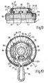
- the dismantling of the device described can take place in a very simple way-as shown in the Figs. 9 and 10. To this purpose, it is sufficient to rotate the handle 23 into an intermediate position-between those of Figs. 1 and 3-i.e. in which the aperture 41 is disposed approximately in correspondence of the pad 40, as has been shown in Fig. 10.
- a simple implement 46-provided with a pair of substantially parallel arms between the handle 23 and the cover 22
- the commutator device of the invention can be considered very simple to mount, with its comprising few parts-that can be constructed with facility by utilizing thermoplastic materials and the usual technology of pressing and injections. Even the mounting of the various parts of the device, results as being rapid and easy. The functioning of this device is moreover, absolutely reliable and secure.
Landscapes
- Health & Medical Sciences (AREA)
- Emergency Medicine (AREA)
- Pulmonology (AREA)
- Engineering & Computer Science (AREA)
- Anesthesiology (AREA)
- Biomedical Technology (AREA)
- Heart & Thoracic Surgery (AREA)
- Hematology (AREA)
- Life Sciences & Earth Sciences (AREA)
- Animal Behavior & Ethology (AREA)
- General Health & Medical Sciences (AREA)
- Public Health (AREA)
- Veterinary Medicine (AREA)
- Percussion Or Vibration Massage (AREA)
- Self-Closing Valves And Venting Or Aerating Valves (AREA)
Description
- The present invention refers to a demand valve for introducing breathable air into a self-breathing apparatus (compressed air breathing apparatus)-in particular, inside the mask of the self-breathing apparatus itself.
- The distributor, along with which the commutator device of the invention can be utilized, is of the type according to GB-A-1.401.613 that comprises a transducer for controlling the movement of a valve element for feeding predetermined quantities of air into a chamber of the distributor itself, following a pressure variation that is verified in said chamber.
- The above-said transducer comprises substantially, a deformable membrane upon one wall of which there rests a stylus, that is made fast with a rod connected to the previously mentioned shutter-element-in such a way that, following a deformation of the membrane, the position of said shutter-element is varied.
- One wall of said membrane also constitutes one of the walls that delimit the above said chamber-and hence, on one of its surfaces, there acts the pressure that exists inside the chamber itself, whilst on the other surface of the same wall, atmospheric pressure is caused to act.
- The distributors ofthetype described are apt for being utilized substantially in two different configurations.
- In a first of these configurations, the above-mentioned transducer is predisposed for controlling the opening of the shutter-element for the purpose of feeding air into the above-said chamber only when the pressure inside it results as being lower than atmospheric pressure.
- For predisposing the distributor for functioning as in said first configuration, it is necessary that, on a first surface of the previously-mentioned membrane wall (that also constitutes one of the surfaces which delimit the said chamber), there acts the pressure existing inside the chamber itself, which atmospheric pressure acts on a second surface of the same wall.
- In this way, said wall is equilibrated between the two pressures-and hence, it is able to shift wheneverthe pressure, inside chamber, descends to below atmospheric pressure.
- For predisposing the distributor for functioning as in the second configuration, it is necessary that, on said first surface, there is also caused to act a predetermined force generated by a spring.
- Under these conditions, the membrane can shift for controlling the opening of the shutter-element, only when the pressure inside the chamber is higher than atmospheric pressure and when the elastic reaction applied by the spring itself is higher than the pressure inside the chamber.
- On the basis of the present invention, there is realized a commutator device for an air distributor, of the type described, which results as being structurally very simple, which can be set-up and dismantled with considerable facility, and whose functioning is safe and reliable.
- On the basis of the present invention, there is realized a demand valve for a breathing apparatus, comprising a transducer for controlling the movements of a valve element for feeding predetermined quantities of air into a chamber in response to a pressure variation inside said chamber, said transducer being activated in response to movement, of a deformable membrane exposed to the pressure which exists in said chamber, said device being apt for switching said distributorfrom a first configuration-wherein, on a first surface of said membrane, there acts the pressure existing inside said chamber, and wherein, on a second surface of the membrane, the atmospheric pressure acts, into a second-configuration wherein, on said second surface, a predetermined force, generated by a spring, is also caused to act, characterized by the fact that said spring is disposed inside a piston which bears against said second surface of said membrane and which is axially mobile inside a cylindrical portion of a cover of the casing of said distributor, said piston being provided with a plurality of radial projections, each of which bears against a corresponding cam surface having a helicoidal profile formed on the lateral surface of said cylindrical portion, with manually operable actuating means for controlling the rotation of said piston about its own axis-and hence, the axial movement of said piston in the spring compressing sense, for switching said distributor from said second configuration into said first configuration, said actuating means comprises a rotatable sleeve, co-axial with said piston and interposed between the latter and said cylindrical portion of the cover, said sleeve being provided with axial slits, inside each of which there is inserted one of said projections, and with an actuating-handle that protrudes above said cover, and said demand valve comprises stopping means for limiting the rotation of the sleeve with respect to said cover between two predetermined angular positions, that are arranged at the angle which is necessary for rotating said sleeve, for moving said piston from the axial position in which it is found in said second configuration into the axial position in which it is found in said first configuration.
- For having a better understanding of the device of the invention, there will now be given, by way of example, the description of one of its particular forms of realization, with referring to the attached drawings, whereby:-
- Fig. 1 shows a plan view of the distributor, in which there is seen incorporated the commutator device of the present invention;
- Fig. 2 shows a cross-section of the distributor of Fig. 1, effectuated with a marked out plane II-II;
- Fig. 3 shows a plan view of the distributor of Fig. 1, in a diverse operative configuration;
- Fig. 4 shows a cross-section of the distributor of Fig. 3, effectuated with a marked out plane III-III;
- Fig. 5 shows a perspective view, in pieces, aptfor illustrating the form of the main elements of the device of the invention;
- Fig. 6 shows a plan view, seen from below, of a sleeve that forms part of the device of the invention;
- Fig. 7 shows a plan view of a small-piston that forms part of this device;
- Fig. 8 shows a plan view seen from above, of a cover of the distributor, in which the device is incorporated;
- Figs. 9 and 10 show two partial sections of the device, apt for pointing out the modalities for dismantling the device itself.
- First and foremost, with reference to Figs. 1 and 2, the commutator device of the invention is destined for an air-distributor-of the type that can be seen partially in Figs. 1 and 2, which comprises a
casing 1 and acover 2, connectable, in any whatsoever convenient way, to the casing itself, for defining inside them a substantiallycylindrical chamber 3. The distributor comprises moreover, a deformable membrane provided with a substantially flat wall 4 and of a lateral substantially cylindrical wall 5 that is provided with a series of corrugations for rendering it axially deformable. Thecircular edge 7 of said membrane is blocked between thecover 2 and the casing 1-in the manner visible in Fig. 2. - A series of
holes 8, made in thecover 2, put into communication the atmosphere with aninternal cavity 9 defined within the membrane itself. With said constructive disposition, the atmospheric pressure acts on thesurface 10 of the wall 4 of the membrane; while on theother surface 11 of the wall itself, there acts the pressure existing inside thechamber 3. - A transducer is apt for controlling the opening of the valve-element (not shown) for feeding air into the
chamber 3. The air is furnished by a source of compressed-air. Said transducer substantially comprises astylus 12, resting on thesurface 11 of the membrane-wall 4, and anactuating rod 13 that is connected with the above-said valve-element, in such a way that-following an axial shifting of the wall 4, the actuatingrod 13 is caused to pivot for varying the passage-hole controlled by the valve-element. - The described distributor is predisposed for functioning in two different configurations. In the first one of these, on the
surfaces chamber 3. Hence, in this configuration, with the wall 4 being equilibrated between the above-said two pressures, the opening of the valve-element is controlled for allowing the entry of the air into the chamber itself, when the pressure inside it is below that of atmospheric pressure (negative pressure). The distributor is moreover in a condition for functioning in a second-configuration-wherein on thesurface 10 of the wall 4, there is also caused to act the force exercised by a spiral-spring 15, which is interposed (in a manner to be explained further on in the text) between thecover 2 and the membrane itself. The above-said spring exercises said axial force on the wall 4, through asmall piston 16, that is axially mobile with respect to thecover 2. - Therefore, in said second, operative configuration, since on the wall 4 there act-apart from the pressures existing in the
chambers spring 15, the opening of the valve-evement is controlled whenever the pressure inside the chamber 3-although still remaining higher than atmosphere pressure (positive pressure), descends to below a predetermined value (equal to the elastic reaction of the spring divided by thefrontal surface 11 of the membrane). - On the basis of the invention, the
small piston 16, is provided with a plurality of radial stakes 18-each one of which is apt for bearing on the active surface 19 (Fig. 5) of acorresponding cam 20, which presents a substantially helicoidal profile and which is made on the internal surface of ahole 17 of thecover 2. The device comprises moreover, a rotatable sleeve 21-which is interposed between said surface and thesmall piston 16. Said sleeve presents a plurality of axial slits 22 (Fig. 5)-in each one of which there is slidingly inserted one of the stakes 18 (as can be seen clearly in Fig. 2). The said sleeve is moreover, provided with an actuating-handle 23-made all in one-piece with the sleeve itself, apt for controlling the rotation of said sleeve. - An annular surface 24 (Fig. 2), made inside the
sleeve 21, constitutes a resting-surface for thespring 15, which is interposed between said surface and another resting-surface 25 made inside thesmall piston 16. Anappendix 26 of thehandle 23, protrudes axially inside thesleeve 21, and it is inserted into the spring itself. - In the instance of the form of realization described, inside the
hole 17 there are made three cams 20-having a phase-displacement angle of 120° substantially, with each of them (as can clearly be seen in Fig. 5) comprising a substantially helicoidal active-surface 19 that is coaxial with the axis of thehole 17 and predisposed for constituting a supporting-surface for acorresponding stake 18 of the small-piston 16, and a corresponding pair of substantially axial stopping-surfaces - The
cover 2 comprises moreover, an annular-relief 32, that protrudes axially above thesurface 33 of the cover itself, and which is provided with a substantially annular-rim 34. Thehandle 23 presents afirst wall 35, that is substantially flat and circular, apt for superimposing the annular-relief 32 having an annular-rim 34, as well as a secondcylindrical wall 36 that is disposed in the outermost peripheral position with respect to the annular-rim 34-as is clearly seen in Fig. 2. - For convenience sake, in the first and
second walls radial grooves 37 that are apt for defining the sectors of the handle 38 (Fig. 1), and thecylindrical wall 36, of each one of these sectors, is provided with radial teeth 39 (Fig. 2), apt for co-operating with the annular-rim 34-in such a way as to allow a spring-fitting of the handle to the cover. - From the annular-
relief 32, there protrudes radially apad 40 apt for coming into contact with the stopping-teeth 39 of thesectors 38, for limiting the end-of-rotation of thehandle 23 with respect to thecover 2, between two prefixed angular positions-which are out of phase with each other, at a suitable angle. - An
aperture 41 is made in thewall 35 of thehandle 23. Said aperture-when said handle is taken to one of the two above-mentioned angular positions, is apt for uncovering a corresponding surface-of-reference rim 34. - Moreover, for convenience sake, a
radial relief 33a is made on thecover 2, above theupper surface 33 of the cover itself. This relief is aligned with the surface-of-reference 43-as can clearly be seen in Fig. 3. - On the lower surface of the
wall 35 of thecover 23 moreover, there is made a pair of cavities 44 (see Fig. 5), 'each one of which is apt for co-operating with acorresponding protuberance 45 made on the rim 34-in such a way as to determine a spring-stop, whenever one of the two above-mentioned angular positions is reached. - The functioning of the commutator device of the invention takes place in the following manner.
- Let us suppose that the commutator device has been set up in such a way as to be disposed in the previously defined first-configuration, i.e. on whose
surfaces chamber 3. In this configuration, the handle 23 (Fig. 1) has been completely rotated in the clockwise direction (shown in Fig. 1), till when theteeth 39 of one of thesectors 38 was made to stop against the pad 40 (Fig. 5). In the same configuration, theaperture 41 uncovers the surface-of-reference 42 (Fig. 1), in such a way as to furnish a visual identification of the configuration wherein the commutator device is found. - When the
handle 23 has been rotated in the above-indicated manner, theslits 22, of thesleeve 21, are found in an angular position with respect to thecover 2, in such a way as to carry thestakes 18 of the small-piston 16 for being disposed substantially on the initial, more raised part, of the active-surface 19 (Figs. 2 and 5) of the cam 20 (as has been shown in Fig. 2). In this configuration, thesmall piston 16 results as being completely inside thehole 14 of the sleeve 21 (as can be clearly seen in Fig. 2) and hence, it does not exercise any action upon thesurface 10 of the membrane wall 4. In said configuration, eachstake 18, becomes stopped by the corresponding blocking-surface 28 (Fig. 5)-that delimits, from one side, each active-surface 19 of thecam 20. - When the commutator device must be taken to the second-configuration-wherein on the
surface 10 of the wall 4, there is also made to act that force exercised by thespring 15, thehandle 23 becomes rotated in the anti-clockwise direction (Fig. 1)―for taking it to the configuration shown in Fig. 3, in which theteeth 39 of one of thesectors 38 becomes stopped against the pad 40 (Fig. 5). In the same configuration, theaperture 41 uncovers the surface-of-reference 43 that is apt for furnishing a visual indication of the new configuration assumed by the device. - In the same configuration, the
aperture 41 is aligned radially with therelief 33a, and hence, in association with the relief itself, it is apt for furnishing a tactile indication of the configuration wherein the device is set up. - Following to the rotation of the
handle 23, thesleeve 21 causes thestakes 18 of this small-piston 16, to rotate. Said piston-under the thrust ofspring 15, moves into thehole 14, while thestakes 18 are guided by the active-surface 19 of thecam 20. At the end of the above-said rotation, the small-piston 16 can go and rest on thesurface 10 of the membrane wall 4 (as is shown in Fig. 4), in such a way as to exercise upon it the force generated by thespring 15. It is evident that-owing to their conformation, thecams 20 realize a substantially helicoidal-bond of the unilateral type, and the small-piston 16 can thereupon assume any whatsoever relative axial position, with respect to thehole 14, depending upon the position of the membrane wall 4. - When the device has once again to be commutated into the first-configuration, the
handle 23 is rotated in the anti-clockwise sense (Fig. 3), and thereupon, the sleeve 21-owing to the coupling of theslits 22 with thestakes 18 of the small-piston 16, causes these stakes to rotate with forcing them to follow the profile-as as result of said rotation and owing to the effect of the coupling with the active-surface 19 of thecams 20, with again taking the small-piston 16 into the initial position of Fig. 2. - The
cavities 44 and theprotuberances 45, are positioned in such a way that one of the former become coupled with the latter, when thehandle 23 is set up in one of the two configurations shown in Figs. 1 or 3, in such a way as to create a spring-action in correspondence of achieving the configurations themselves. - The dismantling of the device described, can take place in a very simple way-as shown in the Figs. 9 and 10. To this purpose, it is sufficient to rotate the
handle 23 into an intermediate position-between those of Figs. 1 and 3-i.e. in which theaperture 41 is disposed approximately in correspondence of thepad 40, as has been shown in Fig. 10. By successively introducing a simple implement 46-provided with a pair of substantially parallel arms, between thehandle 23 and thecover 22, it is possible to determine the widening of thelateral walls 36 of the handle itself (as is clearly shown in Fig. 9), in such a way as to release theteeth 39 of thesectors 38 from the corresponding annular-rim 34. Under these conditions, by exercising, with the implement itself, a certain axial force that tends to detach thehandle 23 from thecover 2, the former can easily be separated from the latter. - For mounting the device, it is sufficient-after having inserted the
spring 15 and the small-piston 16 into thehole 14 of thehandle 23, to introduce thesleeve 21 into thehole 17 of thecover 2, and to successively exercise a small axial force on thehandle 23, in such a way as to elastically deform thelateral walls 36 of thesectors 38, for causing theteeth 39 to jump below theannular rim 34. - Hence, it results as being evident that the commutator device of the invention can be considered very simple to mount, with its comprising few parts-that can be constructed with facility by utilizing thermoplastic materials and the usual technology of pressing and injections. Even the mounting of the various parts of the device, results as being rapid and easy. The functioning of this device is moreover, absolutely reliable and secure.
- What is evident is that, to the form of realization of the present invention which has been described herein, there can also be carried out modifications and variations-both in the form, as well as in the disposition of the various parts, without departing from the ambit of the invention as defined in the claims.
Claims (7)
Applications Claiming Priority (2)
| Application Number | Priority Date | Filing Date | Title |
|---|---|---|---|
| IT2117783 | 1983-05-19 | ||
| IT21177/83A IT1161849B (en) | 1983-05-19 | 1983-05-19 | SWITCHING DEVICE FOR AN AIR DISPENSER INTENDED TO FEED BREATHABLE AIR WITHIN A BREATHING AIR |
Publications (3)
| Publication Number | Publication Date |
|---|---|
| EP0126321A2 EP0126321A2 (en) | 1984-11-28 |
| EP0126321A3 EP0126321A3 (en) | 1985-12-04 |
| EP0126321B1 true EP0126321B1 (en) | 1988-12-07 |
Family
ID=11177929
Family Applications (1)
| Application Number | Title | Priority Date | Filing Date |
|---|---|---|---|
| EP84104609A Expired EP0126321B1 (en) | 1983-05-19 | 1984-04-25 | Demand valve for a breathing apparatus |
Country Status (5)
| Country | Link |
|---|---|
| US (1) | US4592384A (en) |
| EP (1) | EP0126321B1 (en) |
| DE (1) | DE3475474D1 (en) |
| ES (1) | ES532973A0 (en) |
| IT (1) | IT1161849B (en) |
Families Citing this family (4)
| Publication number | Priority date | Publication date | Assignee | Title |
|---|---|---|---|---|
| DE3712390A1 (en) * | 1987-04-11 | 1988-10-27 | Obermayer Anton | Valve |
| US4823828A (en) * | 1987-05-28 | 1989-04-25 | Mcginnis Gerald E | Pressure relief valve |
| DE10125076C1 (en) * | 2001-05-14 | 2002-05-23 | Msa Auer Gmbh | Automatic lung, for pressurized air respiration device, has blocking lever for securing membrane in operating pause provided with safety restraint preventing release by mechanical shock |
| CN105916539B (en) * | 2013-11-20 | 2018-07-24 | 弗路德自动控制系统有限公司 | Valve for controlling stream |
Family Cites Families (6)
| Publication number | Priority date | Publication date | Assignee | Title |
|---|---|---|---|---|
| AT152622B (en) * | 1936-04-24 | 1938-02-25 | Degea Ag Auergesellschaft | Air attachment for high altitude breathing apparatus. |
| US2552595A (en) * | 1948-09-21 | 1951-05-15 | Seeler Henry | Oxygen demand breathing system, including means for automatic altitude regulation |
| US3360007A (en) * | 1965-08-02 | 1967-12-26 | Thomas N Haidek | Gas pressure and vacuum pull control valve |
| GB1401613A (en) * | 1971-07-05 | 1975-07-16 | Siebe Gorman & Co Ltd | Flow-control devices |
| US3866622A (en) * | 1972-03-18 | 1975-02-18 | Kawasaki Heavy Ind Ltd | Open circuit breathing apparatus |
| US4207884A (en) * | 1976-12-20 | 1980-06-17 | Max Isaacson | Pressure controlled breathing apparatus |
-
1983
- 1983-05-19 IT IT21177/83A patent/IT1161849B/en active
-
1984
- 1984-04-25 EP EP84104609A patent/EP0126321B1/en not_active Expired
- 1984-04-25 DE DE8484104609T patent/DE3475474D1/en not_active Expired
- 1984-05-18 US US06/611,888 patent/US4592384A/en not_active Expired - Fee Related
- 1984-05-18 ES ES532973A patent/ES532973A0/en active Granted
Also Published As
| Publication number | Publication date |
|---|---|
| ES8503252A1 (en) | 1985-02-16 |
| EP0126321A3 (en) | 1985-12-04 |
| US4592384A (en) | 1986-06-03 |
| EP0126321A2 (en) | 1984-11-28 |
| IT1161849B (en) | 1987-03-18 |
| IT8321177A1 (en) | 1984-11-19 |
| IT8321177A0 (en) | 1983-05-19 |
| DE3475474D1 (en) | 1989-01-12 |
| ES532973A0 (en) | 1985-02-16 |
Similar Documents
| Publication | Publication Date | Title |
|---|---|---|
| EP4278095B1 (en) | Air pump assembly for an inflatable product | |
| US3633621A (en) | Snap-fitted pneumatic selector valve having a tubular conduit for fluid flow switching | |
| JP3198150U (en) | Air compressor equipment | |
| US7137657B2 (en) | Reinforced apparatus for a lever handle of a door lock | |
| JP7554811B2 (en) | Versatile and removable pump system and method for inflating and deflating an inflatable object - Patents.com | |
| KR20020090119A (en) | Valve driving apparatus | |
| JPH0436816B2 (en) | ||
| US2414966A (en) | Valve assembly | |
| US6318701B1 (en) | Pneumatic actuator | |
| US6511040B2 (en) | Pneumatic actuator | |
| US7210902B2 (en) | Two-way air pump | |
| EP0126321A2 (en) | Demand valve for a breathing apparatus | |
| KR101690042B1 (en) | Pumping device for vehicle seat | |
| US3973582A (en) | Flexible band device | |
| US3253667A (en) | Multiple elevation air bearing device | |
| CN213271123U (en) | A push valve and outlet faucet | |
| US6827001B2 (en) | Pressure actuator diaphragm casing with air passages | |
| WO2008027104A1 (en) | Lever positioning device for valve actuator | |
| KR950020827A (en) | Control switch | |
| CN219102140U (en) | Inflation and deflation valve and inflation tool applied by same | |
| CN118204736B (en) | Positioning device for accurate positioning of rings in gas meter assembly lines | |
| US3708136A (en) | Magnetic tape unit having a pneumatic reel hub | |
| KR960012674B1 (en) | Push switch | |
| US3550627A (en) | Rotary fluid valve construction | |
| EP4370086B1 (en) | Airway structure of a massage pool with compensation function and massage pool |
Legal Events
| Date | Code | Title | Description |
|---|---|---|---|
| PUAI | Public reference made under article 153(3) epc to a published international application that has entered the european phase |
Free format text: ORIGINAL CODE: 0009012 |
|
| AK | Designated contracting states |
Designated state(s): DE FR GB SE |
|
| PUAL | Search report despatched |
Free format text: ORIGINAL CODE: 0009013 |
|
| AK | Designated contracting states |
Designated state(s): DE FR GB SE |
|
| 17P | Request for examination filed |
Effective date: 19860523 |
|
| 17Q | First examination report despatched |
Effective date: 19870813 |
|
| GRAA | (expected) grant |
Free format text: ORIGINAL CODE: 0009210 |
|
| AK | Designated contracting states |
Kind code of ref document: B1 Designated state(s): DE FR GB SE |
|
| REF | Corresponds to: |
Ref document number: 3475474 Country of ref document: DE Date of ref document: 19890112 |
|
| ET | Fr: translation filed | ||
| PLBE | No opposition filed within time limit |
Free format text: ORIGINAL CODE: 0009261 |
|
| STAA | Information on the status of an ep patent application or granted ep patent |
Free format text: STATUS: NO OPPOSITION FILED WITHIN TIME LIMIT |
|
| 26N | No opposition filed | ||
| PGFP | Annual fee paid to national office [announced via postgrant information from national office to epo] |
Ref country code: FR Payment date: 19930316 Year of fee payment: 10 |
|
| PGFP | Annual fee paid to national office [announced via postgrant information from national office to epo] |
Ref country code: SE Payment date: 19930318 Year of fee payment: 10 |
|
| PGFP | Annual fee paid to national office [announced via postgrant information from national office to epo] |
Ref country code: GB Payment date: 19930322 Year of fee payment: 10 |
|
| PGFP | Annual fee paid to national office [announced via postgrant information from national office to epo] |
Ref country code: DE Payment date: 19930630 Year of fee payment: 10 |
|
| PG25 | Lapsed in a contracting state [announced via postgrant information from national office to epo] |
Ref country code: GB Effective date: 19940425 |
|
| PG25 | Lapsed in a contracting state [announced via postgrant information from national office to epo] |
Ref country code: SE Effective date: 19940426 |
|
| GBPC | Gb: european patent ceased through non-payment of renewal fee |
Effective date: 19940425 |
|
| PG25 | Lapsed in a contracting state [announced via postgrant information from national office to epo] |
Ref country code: FR Effective date: 19941229 |
|
| PG25 | Lapsed in a contracting state [announced via postgrant information from national office to epo] |
Ref country code: DE Effective date: 19950103 |
|
| EUG | Se: european patent has lapsed |
Ref document number: 84104609.7 Effective date: 19941110 |
|
| REG | Reference to a national code |
Ref country code: FR Ref legal event code: ST |