EP0126108B1 - Control/fire damper for ducts in ventilation installations - Google Patents
Control/fire damper for ducts in ventilation installations Download PDFInfo
- Publication number
- EP0126108B1 EP0126108B1 EP19830903543 EP83903543A EP0126108B1 EP 0126108 B1 EP0126108 B1 EP 0126108B1 EP 19830903543 EP19830903543 EP 19830903543 EP 83903543 A EP83903543 A EP 83903543A EP 0126108 B1 EP0126108 B1 EP 0126108B1
- Authority
- EP
- European Patent Office
- Prior art keywords
- fire damper
- control
- clamping
- clamping device
- counterpart
- Prior art date
- Legal status (The legal status is an assumption and is not a legal conclusion. Google has not performed a legal analysis and makes no representation as to the accuracy of the status listed.)
- Expired
Links
- 238000009434 installation Methods 0.000 title claims description 4
- 238000009423 ventilation Methods 0.000 title claims description 4
- 239000000463 material Substances 0.000 claims abstract description 7
- 239000002184 metal Substances 0.000 claims description 3
- 238000010276 construction Methods 0.000 description 2
- 230000008018 melting Effects 0.000 description 1
- 238000002844 melting Methods 0.000 description 1
- 238000003801 milling Methods 0.000 description 1
- 238000006467 substitution reaction Methods 0.000 description 1
Images


Classifications
-
- A—HUMAN NECESSITIES
- A62—LIFE-SAVING; FIRE-FIGHTING
- A62C—FIRE-FIGHTING
- A62C2/00—Fire prevention or containment
- A62C2/06—Physical fire-barriers
- A62C2/12—Hinged dampers
-
- F—MECHANICAL ENGINEERING; LIGHTING; HEATING; WEAPONS; BLASTING
- F24—HEATING; RANGES; VENTILATING
- F24F—AIR-CONDITIONING; AIR-HUMIDIFICATION; VENTILATION; USE OF AIR CURRENTS FOR SCREENING
- F24F13/00—Details common to, or for air-conditioning, air-humidification, ventilation or use of air currents for screening
- F24F13/08—Air-flow control members, e.g. louvres, grilles, flaps or guide plates
- F24F13/10—Air-flow control members, e.g. louvres, grilles, flaps or guide plates movable, e.g. dampers
- F24F13/14—Air-flow control members, e.g. louvres, grilles, flaps or guide plates movable, e.g. dampers built up of tilting members, e.g. louvre
- F24F13/1426—Air-flow control members, e.g. louvres, grilles, flaps or guide plates movable, e.g. dampers built up of tilting members, e.g. louvre characterised by actuating means
- F24F2013/144—Air-flow control members, e.g. louvres, grilles, flaps or guide plates movable, e.g. dampers built up of tilting members, e.g. louvre characterised by actuating means with thermoactuators
-
- Y—GENERAL TAGGING OF NEW TECHNOLOGICAL DEVELOPMENTS; GENERAL TAGGING OF CROSS-SECTIONAL TECHNOLOGIES SPANNING OVER SEVERAL SECTIONS OF THE IPC; TECHNICAL SUBJECTS COVERED BY FORMER USPC CROSS-REFERENCE ART COLLECTIONS [XRACs] AND DIGESTS
- Y10—TECHNICAL SUBJECTS COVERED BY FORMER USPC
- Y10T—TECHNICAL SUBJECTS COVERED BY FORMER US CLASSIFICATION
- Y10T137/00—Fluid handling
- Y10T137/1624—Destructible or deformable element controlled
- Y10T137/1797—Heat destructible or fusible
- Y10T137/1819—Safety cut-off
Definitions
- the present invention concerns a control/fire damper for ducts in ventilation installations according to the pre-characterizing portion of claim 1.
- the fire limiter of the Finnish Patent No. 54767 (see also CA-A-1116921), the fuse is a separate fuse attached to an adjusting cable or wire passing through the shell, and the closing plate is turnable into desired position with reference to the flow duct by the aid of the adjusting cable or wire, in order to produce the desired throttling.
- a drawback of this design is, in addition to inconvenient restoring operation after the closing plate has been trigged, that the fuse replacement operation is exceedingly cumbersome, and it is difficult after such replacement to reposition the closing plate exactly as before if the new fuse has different dimensions.
- the object of the present invention is to provide an improvement in control/fire dampers known in the art.
- a more detailed object of the invention is to provide a control/fire damper having its clamping mechanism inside the flow duct, bet permitting the closing member to be adjusted from outside the damper and, in the case of a fire damper, fuse replacement from the outside.
- a further object of the invention is to provide a fire limiter in which fuse replacement does not impede the resetting of the closing member of the fire limiter in its former position.
- control/fire damper which is provided with the feature of the characterizing portion of claim 1.
- the rest of the characteristic features of the control/fire damper of the invention are stated in claims 2-5.
- control/fire damper of the invention numerous remarkable advantages are gained.
- the clamping counterpart and the clamping device are located inside the means, where space is always to be found for them, and they are well protected, not outside the means, where the availability of space is often restricted or its use may cause inconvenience for instance in connection with the lagging of the duct.
- the setting of the closing member can be carried out from outside the damper with ease.
- the fuse which may be made contiguous with the clamping screw, can be replaced from the outside of the damper, without access to the inside.
- An advantage lies moreover therein that the only necessary structural difference between a control damper and a combined control/fire damper is in the screw of the clamping device.
- the control/fire damper depicted in Figs. 1 and 2 has been generally indicated by the reference numeral 10.
- the control/fire damper comprises a shell 11, constituting a through-flow duct 12.
- a shaft 13 carried in the shell 11 by its ends.
- a closing member or closing plate 14 On the shaft 13 is mounted a closing member or closing plate 14 in the way that the closing plate 14 can turn from the closed position shown in Fig. 2, in which it is positioned substantially at right angles against the axial direction of the duct, to an open position in which it lies substantially parallel to the axial direction of the through-flow duct 12.
- a clamping arc 15 as clamping couterpart, which in the present embodiment is wire-like, and which passes through the clamping device 16, where the clamping screw 20 depicted in Figs. 7 and 8 by mediation of the clamping arc 15 fixes the closing plate 14 in desired position.
- the force required for closing the closing plate 14 is obtained with the aid of closing springs 17 placed on the end, or ends, of the shaft 13.
- the clamping device 16 may be located outside the motion range defined by the open-closed positions of the closing plate 14.
- control/fire damper 10 of the invention includes a limiter pin or limiter strips 18 serving to accomplish tight closure.
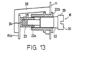
- a fuse of this kind may, as shown in Figs. 7,8 and 13, be provided by joining to the end of the clamping screw 20 a member 23 furnished with fuse material 25, and which when the fuse material reaches its melting point becomes detached or moves, at the same time releasing the clamping arc 15 from its clamping whereby the closing plate 14 closes. Substitution of a new fuse for the old fuse is feasible with greatest ease by replacing the clamping screw 20.
- the operation of the control/fire damper 20 of Figs. 1 and 2 is as follows.
- the closing plate 14 is with the aid of the adjusting or control cable 19 placed in the desired open position.
- the clamping arc 15 is clamped to be immobile by means of the clamping device 16.
- the temperature in the flow duct 12 rises to a pre-determined limit value, the member 23 connected to the clamping screw 20 with fuse material becomes detached, or moves.
- the closing plate 14 turns by action of the spring force of the closing spring or springs 17 and becomes closed against the limiter pin or strips 18.
- the resetting of the fire limiter 10 of the invention is simple and easy. To do this, it is merely necessary to install a new clamping screw 20, and the fire limiter 10 will be operative again.
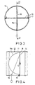
- FIG. 3 and 4 The embodiment depicted in Figs. 3 and 4 is in other respects the same as the embodiment of Figs. 1 and 2, except that in the embodiment of Figs. 3 and 4 is used, for clamping arc 15a, a plate of which the margin has substantially the shape of a circular arc.
- a clamping device appropriate for this embodiment is presented in Figs. 9 and 10, the clamping device presented here consisting of a clamping screw 20 and of a member 23, possibly joined with its end by fuse material 25 as in Fig. 13, this member being given such shape that it is appropriate for forming a clamping interlock with the plate 15a.
- Fixing of the clamping arc 15a may alternatively be accomplished, as shown in Fig. 13, also in that to the shell 11 of the control/fire damper 10 is attached a shaped counterpiece 26, and a clamping arc 15a, in this embodiment advantageously located on one margin of the closing plate, is clamped with the aid of the clamping device and of said counterpiece so that the clamping arc 15a is impacted between an end portion or bottom 24 of the sleeve-like member 23 of the clamping device 16 and the counterpiece 26.
- Positive fixing of the clamping arc 15a is simply and easily accomplished by tightening the clamping screw 20 of the clamping device 16.
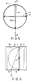
- Figs. 5 and 6 is the same in other respects as the embodiment presented in Figs. 1 and 2, except that in the embodiment of Figs. 5 and 6 a sheet metal strip 15b is used for clamping arc.
- a clamping device appropriate for use in this embodiment is shown in Figs. 11 and 12.
- the clamping device 16 consists of a clamping screw 20 and a member 23, possibly joined as shown in Fig. 13 to its end by mediation of fuse material 25, and this member being so shaped that it is appropriate for interlocking with the rigid sheet metal strip 15b.
- any such control measure is easy and simple to carry out. It is then only necessary to free the clamping plate 15 from its clamping by the clamping device 16 and to pull the adjusting cable 19 outwards, whereby the closing plate 14 will correspondingly turn and throttle the flow duct 12.
- the clamping plate 15 is once again clamped to be immovable, by the aid of the clamping device 16.
- an adjusting cable 19 as in the figure is not absolutely necessary: it may be replaced by another equivalent design; for instance, one end of the shaft 13 may be bent to form a crank, or the end of the shaft 13 may be provided by milling with a screwdriver slot or spanner flats, or a hex screw head may be welded on, whereby adjustment becomes feasible with the aid of an appropriate tool.
Landscapes
- Health & Medical Sciences (AREA)
- Public Health (AREA)
- Business, Economics & Management (AREA)
- Emergency Management (AREA)
- Air-Flow Control Members (AREA)
Abstract
Description
- The present invention concerns a control/fire damper for ducts in ventilation installations according to the pre-characterizing portion of claim 1.
- At present, in a number of structural designs known in the art, fixing of the closing member or closing plate in desired position is effected outside the damper by the aid of screw clamping between a sector plate or equivalent and its counterpiece. However, structures of this kind have the drawback of a certain space requirement outside the duct, which frequently entails difficulties in installation. In addition, the construction is susceptible to damage; it. interferes with the lagging of the duct; and its appearance is not always acceptable, as is stated e.g. in the Norwegian patent application No. 802081 (see NO-B-148700).
- In another structure known in the art, the fire limiter of the Finnish Patent No. 54767 (see also CA-A-1116921), the fuse is a separate fuse attached to an adjusting cable or wire passing through the shell, and the closing plate is turnable into desired position with reference to the flow duct by the aid of the adjusting cable or wire, in order to produce the desired throttling. A drawback of this design is, in addition to inconvenient restoring operation after the closing plate has been trigged, that the fuse replacement operation is exceedingly cumbersome, and it is difficult after such replacement to reposition the closing plate exactly as before if the new fuse has different dimensions.
- The object of the present invention is to provide an improvement in control/fire dampers known in the art. A more detailed object of the invention is to provide a control/fire damper having its clamping mechanism inside the flow duct, bet permitting the closing member to be adjusted from outside the damper and, in the case of a fire damper, fuse replacement from the outside. A further object of the invention is to provide a fire limiter in which fuse replacement does not impede the resetting of the closing member of the fire limiter in its former position.
- The aims of the invention are achieved by a control/fire damper which is provided with the feature of the characterizing portion of claim 1. The rest of the characteristic features of the control/fire damper of the invention are stated in claims 2-5.
- With the control/fire damper of the invention, numerous remarkable advantages are gained. In the control/fire damper of the invention, the clamping counterpart and the clamping device are located inside the means, where space is always to be found for them, and they are well protected, not outside the means, where the availability of space is often restricted or its use may cause inconvenience for instance in connection with the lagging of the duct. It is moreover of importance that the setting of the closing member can be carried out from outside the damper with ease. It is moreover of primary importance that in the case of a fire damper the fuse, which may be made contiguous with the clamping screw, can be replaced from the outside of the damper, without access to the inside. An advantage lies moreover therein that the only necessary structural difference between a control damper and a combined control/fire damper is in the screw of the clamping device.
- The invention is described in detail referring to certain avantageous embodiments of the invention presented in the figures of the drawing attached, whereto the invention is not, however, intended to be exclusively confined.
-
- Fig. 1 presents a control/fire damper according to the invention in end view.
- Fig. 2 shows a section along the line 11-11 in Fig. 1, with the closing plate on closed position.
- Fig. 3 presents another advantageous embodiment of the control/fire damper of the invention in end view.
- . Fig. 4 presents the section along the line IV-IV in Fig. 3, with the closing plate in closed position.
- Fig. 5 presents a third advantageous embodiment of the control/fire damper of the invention in end view.
- Fig. 6 presents the section along the line VI-VI in Fig. 5, with the closing plate in closed position.
- Fig. 7 presents an advantageous embodiment of the clamping device employed in the control/ fire damper of the invention, in elevational view.
- Fig. 8 presents the section along the line VIII-VIII in Fig. 7.
- Fig. 9 presents another advantageous embodiment of the clamping device used in the control/ fire damper. of the invention, in elevational view.
- Fig. 10 presents the section along the line X-X in Fig. 9.
- Fig. 11 presents a third advantageous embodiment of the clamping device used in the control/ fire damper of the invention, in elevational view.
- Fig. 12 presents the section along the line XII-XII in Fig. 11.
- Fig. 13 presents a fuse device mounted on a fire damper, in schematic cross-section.
- The control/fire damper depicted in Figs. 1 and 2 has been generally indicated by the
reference numeral 10. The control/fire damper comprises ashell 11, constituting a through-flow duct 12. Within theflow duct 12 has been disposed ashaft 13, carried in theshell 11 by its ends. On theshaft 13 is mounted a closing member orclosing plate 14 in the way that theclosing plate 14 can turn from the closed position shown in Fig. 2, in which it is positioned substantially at right angles against the axial direction of the duct, to an open position in which it lies substantially parallel to the axial direction of the through-flow duct 12. - To the
closing plate 14 is attached aclamping arc 15 as clamping couterpart, which in the present embodiment is wire-like, and which passes through theclamping device 16, where theclamping screw 20 depicted in Figs. 7 and 8 by mediation of theclamping arc 15 fixes theclosing plate 14 in desired position. The force required for closing theclosing plate 14 is obtained with the aid of closingsprings 17 placed on the end, or ends, of theshaft 13. Theclamping device 16 may be located outside the motion range defined by the open-closed positions of theclosing plate 14. - In order that the
closing plate 14, when closing, might remain in a position perpendicular to theflow duct 12, the control/fire damper 10 of the invention includes a limiter pin orlimiter strips 18 serving to accomplish tight closure. - To the
closing plate 14 is attached acontrol cable 19, passing out through theshell 11. - In the fire damper of Figs. 1 and 2, it is possible to construct in connection with the clamping screw 20 a clamping fuse matching the construction. A fuse of this kind may, as shown in Figs. 7,8 and 13, be provided by joining to the end of the clamping screw 20 a
member 23 furnished withfuse material 25, and which when the fuse material reaches its melting point becomes detached or moves, at the same time releasing theclamping arc 15 from its clamping whereby theclosing plate 14 closes. Substitution of a new fuse for the old fuse is feasible with greatest ease by replacing theclamping screw 20. - The operation of the control/
fire damper 20 of Figs. 1 and 2 is as follows. When the control/fire damper 10 is joined to a duct in a ventilation system, theclosing plate 14 is with the aid of the adjusting orcontrol cable 19 placed in the desired open position. The clampingarc 15 is clamped to be immobile by means of theclamping device 16. lf, in the case of a fire damper, the temperature in theflow duct 12 rises to a pre-determined limit value, themember 23 connected to theclamping screw 20 with fuse material becomes detached, or moves. Hereby, theclosing plate 14 turns by action of the spring force of the closing spring orsprings 17 and becomes closed against the limiter pin orstrips 18. The resetting of thefire limiter 10 of the invention is simple and easy. To do this, it is merely necessary to install anew clamping screw 20, and thefire limiter 10 will be operative again. - The embodiment depicted in Figs. 3 and 4 is in other respects the same as the embodiment of Figs. 1 and 2, except that in the embodiment of Figs. 3 and 4 is used, for clamping
arc 15a, a plate of which the margin has substantially the shape of a circular arc. A clamping device appropriate for this embodiment is presented in Figs. 9 and 10, the clamping device presented here consisting of aclamping screw 20 and of amember 23, possibly joined with its end byfuse material 25 as in Fig. 13, this member being given such shape that it is appropriate for forming a clamping interlock with theplate 15a. - Fixing of the
clamping arc 15a may alternatively be accomplished, as shown in Fig. 13, also in that to theshell 11 of the control/fire damper 10 is attached ashaped counterpiece 26, and aclamping arc 15a, in this embodiment advantageously located on one margin of the closing plate, is clamped with the aid of the clamping device and of said counterpiece so that theclamping arc 15a is impacted between an end portion orbottom 24 of the sleeve-like member 23 of theclamping device 16 and thecounterpiece 26. Positive fixing of theclamping arc 15a is simply and easily accomplished by tightening theclamping screw 20 of theclamping device 16. - Also the embodiment depicted in Figs. 5 and 6 is the same in other respects as the embodiment presented in Figs. 1 and 2, except that in the embodiment of Figs. 5 and 6 a sheet metal strip 15b is used for clamping arc. A clamping device appropriate for use in this embodiment is shown in Figs. 11 and 12. In this embodiment, too, the
clamping device 16 consists of aclamping screw 20 and amember 23, possibly joined as shown in Fig. 13 to its end by mediation offuse material 25, and this member being so shaped that it is appropriate for interlocking with the rigid sheet metal strip 15b. - If it is desired to alter the position of the
closing plate 14 of a control/fire damper 10 according to the invention which has been commissioned for use, in order to throttle theflow duct 12, any such control measure is easy and simple to carry out. It is then only necessary to free theclamping plate 15 from its clamping by theclamping device 16 and to pull the adjustingcable 19 outwards, whereby theclosing plate 14 will correspondingly turn and throttle theflow duct 12. When theclosing plate 14 has reached the desired control position, theclamping plate 15 is once again clamped to be immovable, by the aid of theclamping device 16. - In the control/fire damper of the invention, an
adjusting cable 19 as in the figure is not absolutely necessary: it may be replaced by another equivalent design; for instance, one end of theshaft 13 may be bent to form a crank, or the end of theshaft 13 may be provided by milling with a screwdriver slot or spanner flats, or a hex screw head may be welded on, whereby adjustment becomes feasible with the aid of an appropriate tool.
Claims (5)
Applications Claiming Priority (2)
| Application Number | Priority Date | Filing Date | Title |
|---|---|---|---|
| FI823900A FI70144C (en) | 1982-11-12 | 1982-11-12 | REGULATOR- / BRANDSPJAELL FOER KANALER I VENTILATIONSANLAEGGNINGAR |
| FI823900 | 1982-11-12 |
Publications (2)
| Publication Number | Publication Date |
|---|---|
| EP0126108A1 EP0126108A1 (en) | 1984-11-28 |
| EP0126108B1 true EP0126108B1 (en) | 1986-11-26 |
Family
ID=8516297
Family Applications (1)
| Application Number | Title | Priority Date | Filing Date |
|---|---|---|---|
| EP19830903543 Expired EP0126108B1 (en) | 1982-11-12 | 1983-11-11 | Control/fire damper for ducts in ventilation installations |
Country Status (5)
| Country | Link |
|---|---|
| US (1) | US4625626A (en) |
| EP (1) | EP0126108B1 (en) |
| DE (1) | DE3367858D1 (en) |
| FI (1) | FI70144C (en) |
| WO (1) | WO1984001907A1 (en) |
Families Citing this family (14)
| Publication number | Priority date | Publication date | Assignee | Title |
|---|---|---|---|---|
| WO1986005107A1 (en) * | 1985-03-01 | 1986-09-12 | Eero Taimisto | Apparatus for adjusting and releasing a fire damper and an apparatus for operating a fire damper |
| CH664500A5 (en) * | 1985-03-21 | 1988-03-15 | Spiro Investment Ag | FIRE-RESISTANT DEVICE FOR VENTILATION OR AIR CONDITIONING AIR DUCTS. |
| US4936388A (en) * | 1986-09-17 | 1990-06-26 | Le Lande Jr Walter C | Fire suppression system |
| US4991657A (en) * | 1986-09-17 | 1991-02-12 | Lelande Jr Walter C | Fire suppression system |
| US4867376A (en) * | 1986-10-17 | 1989-09-19 | Arceneaux Henry M | Air control system |
| US5238220A (en) * | 1990-08-02 | 1993-08-24 | The Boeing Company | Manually and electrically controlled butterfly valve |
| US5787919A (en) * | 1996-12-06 | 1998-08-04 | Lamiflow Air Systems, Inc. | Pressure differential indicator with fire damper |
| US6918402B2 (en) * | 2000-09-28 | 2005-07-19 | Bruce Harvey | Flow control apparatus |
| AU2002220847A1 (en) * | 2000-12-01 | 2002-06-11 | Tri-Air Innovations Limited | Air flow controller and fire damper in an air flow duct |
| GB0029381D0 (en) * | 2000-12-01 | 2001-01-17 | Tri Air Innovations Ltd | Air flow controller and fire damper in air flow duct |
| GB2422542B (en) * | 2002-08-19 | 2007-01-31 | Kent Tooling & Components Ltd | Thermally-Actuated Cartridge And Fire Damper |
| US7125332B2 (en) * | 2003-12-23 | 2006-10-24 | Pci Industries, Inc. | Ceiling radiation damper and mounting method |
| USD635239S1 (en) * | 2010-01-24 | 2011-03-29 | Glv International (1995) Ltd. | Draft blocker |
| AU2019203399B2 (en) * | 2018-05-21 | 2020-12-24 | Price Holyoake (NZ) Limited | Fire Damper |
Citations (2)
| Publication number | Priority date | Publication date | Assignee | Title |
|---|---|---|---|---|
| US1924869A (en) * | 1932-03-11 | 1933-08-29 | Kitson Company | Protection valve device for water meters and the like |
| US4221231A (en) * | 1976-02-27 | 1980-09-09 | Dunlop Limited | Thermal fuse device |
Family Cites Families (8)
| Publication number | Priority date | Publication date | Assignee | Title |
|---|---|---|---|---|
| US18912A (en) * | 1857-12-22 | ketcbam | ||
| US1128228A (en) * | 1913-09-24 | 1915-02-09 | Adoniram J Collar | Hydraulic valve. |
| US2218330A (en) * | 1939-01-10 | 1940-10-15 | Bell Telephone Labor Inc | Ventilator |
| US2774366A (en) * | 1954-09-24 | 1956-12-18 | Standard Oil Co | Temperature-responsive check valve |
| DE2261153A1 (en) * | 1972-12-11 | 1974-07-04 | Nordluft Norddeutsche Ges Fuer | WITH A PIVOTING FIRE PROTECTION FLAP EQUIPPED WITH A CLOSING FORCE FOR VENTILATION SYSTEMS |
| FI54767C (en) * | 1977-03-01 | 1979-03-12 | Halton Oy | BRANDSPAERR FOER KANALER I VENTILATIONSANLAEGGNINGAR |
| NO148700C (en) * | 1980-07-10 | 1983-11-30 | Per Bj Simble | DEVICE FOR FIREBOARD FOR FITTING IN VENTILATION CHANNEL |
| SE8200487L (en) * | 1982-01-29 | 1983-07-30 | Svenska Flaektfabriken Ab | FROM AIR VALVE |
-
1982
- 1982-11-12 FI FI823900A patent/FI70144C/en not_active IP Right Cessation
-
1983
- 1983-11-11 DE DE8383903543T patent/DE3367858D1/en not_active Expired
- 1983-11-11 EP EP19830903543 patent/EP0126108B1/en not_active Expired
- 1983-11-11 WO PCT/FI1983/000070 patent/WO1984001907A1/en not_active Ceased
- 1983-11-11 US US06/629,832 patent/US4625626A/en not_active Expired - Lifetime
Patent Citations (2)
| Publication number | Priority date | Publication date | Assignee | Title |
|---|---|---|---|---|
| US1924869A (en) * | 1932-03-11 | 1933-08-29 | Kitson Company | Protection valve device for water meters and the like |
| US4221231A (en) * | 1976-02-27 | 1980-09-09 | Dunlop Limited | Thermal fuse device |
Also Published As
| Publication number | Publication date |
|---|---|
| FI823900A0 (en) | 1982-11-12 |
| FI823900L (en) | 1984-05-13 |
| US4625626A (en) | 1986-12-02 |
| DE3367858D1 (en) | 1987-01-15 |
| FI70144B (en) | 1986-02-28 |
| EP0126108A1 (en) | 1984-11-28 |
| FI70144C (en) | 1986-09-15 |
| WO1984001907A1 (en) | 1984-05-24 |
Similar Documents
| Publication | Publication Date | Title |
|---|---|---|
| US4625626A (en) | Control/fire damper for ducts inventilation installations | |
| US4474167A (en) | Latch for a butterfly damper | |
| RU2268445C2 (en) | Gal flow regulator and case for the regulator | |
| US4390123A (en) | Thermally activated, automatic, single blade damper and damper operator | |
| US3495521A (en) | Manual adjustable control for air valve dampers | |
| US4263930A (en) | Diffuser concealable, volume control, heat-responsive, semi-automatic resetting, butterfly damper and operator | |
| JPH06510625A (en) | Vacuum circuit breaker with operating device and pole operating unit | |
| US2400044A (en) | Damper structure | |
| US7275560B2 (en) | Pressure relief door for air duct work | |
| US4295486A (en) | Low cost, diffuser concealable, volume control, heat responsive, resettable, butterfly damper operator | |
| US4109564A (en) | Ventilation element with tubular connector for insertion into an opening in a ceiling or a wall | |
| US5207615A (en) | Damper assembly for air plenum system | |
| US5927686A (en) | Sound dampening duct damper | |
| US4543941A (en) | Valve for furnace stack pipe | |
| US2541346A (en) | Furnace volume control | |
| US4399940A (en) | Automatic stove damper control | |
| US6250326B1 (en) | Dual temperature fire damper releasing system | |
| US4497310A (en) | Flue box with adjustable counterbalance cap | |
| US3342212A (en) | Volume temperature control device for air outlet devices | |
| US6508246B1 (en) | Mechanical draft controller | |
| US4372342A (en) | Balancing damper with quick set adjustment bracket | |
| US4553422A (en) | Tap duct crimping tool | |
| US2177931A (en) | Coiled shutter for enclosures | |
| US4470401A (en) | Valve for furnace stack pipe | |
| US3669152A (en) | Butterfly damper |
Legal Events
| Date | Code | Title | Description |
|---|---|---|---|
| PUAI | Public reference made under article 153(3) epc to a published international application that has entered the european phase |
Free format text: ORIGINAL CODE: 0009012 |
|
| 17P | Request for examination filed |
Effective date: 19840703 |
|
| AK | Designated contracting states |
Designated state(s): DE FR GB SE |
|
| GRAA | (expected) grant |
Free format text: ORIGINAL CODE: 0009210 |
|
| AK | Designated contracting states |
Kind code of ref document: B1 Designated state(s): DE FR GB SE |
|
| REF | Corresponds to: |
Ref document number: 3367858 Country of ref document: DE Date of ref document: 19870115 |
|
| ET | Fr: translation filed | ||
| PLBE | No opposition filed within time limit |
Free format text: ORIGINAL CODE: 0009261 |
|
| STAA | Information on the status of an ep patent application or granted ep patent |
Free format text: STATUS: NO OPPOSITION FILED WITHIN TIME LIMIT |
|
| 26N | No opposition filed | ||
| EAL | Se: european patent in force in sweden |
Ref document number: 83903543.3 |
|
| PGFP | Annual fee paid to national office [announced via postgrant information from national office to epo] |
Ref country code: FR Payment date: 19961030 Year of fee payment: 14 |
|
| PGFP | Annual fee paid to national office [announced via postgrant information from national office to epo] |
Ref country code: SE Payment date: 19961118 Year of fee payment: 14 |
|
| PGFP | Annual fee paid to national office [announced via postgrant information from national office to epo] |
Ref country code: DE Payment date: 19961231 Year of fee payment: 14 |
|
| PG25 | Lapsed in a contracting state [announced via postgrant information from national office to epo] |
Ref country code: SE Free format text: LAPSE BECAUSE OF NON-PAYMENT OF DUE FEES Effective date: 19971112 |
|
| PG25 | Lapsed in a contracting state [announced via postgrant information from national office to epo] |
Ref country code: FR Free format text: THE PATENT HAS BEEN ANNULLED BY A DECISION OF A NATIONAL AUTHORITY Effective date: 19971130 |
|
| PG25 | Lapsed in a contracting state [announced via postgrant information from national office to epo] |
Ref country code: DE Free format text: LAPSE BECAUSE OF NON-PAYMENT OF DUE FEES Effective date: 19980801 |
|
| EUG | Se: european patent has lapsed |
Ref document number: 83903543.3 |
|
| REG | Reference to a national code |
Ref country code: FR Ref legal event code: ST |
|
| REG | Reference to a national code |
Ref country code: GB Ref legal event code: IF02 |
|
| PGFP | Annual fee paid to national office [announced via postgrant information from national office to epo] |
Ref country code: GB Payment date: 20021106 Year of fee payment: 20 |
|
| PG25 | Lapsed in a contracting state [announced via postgrant information from national office to epo] |
Ref country code: GB Free format text: LAPSE BECAUSE OF EXPIRATION OF PROTECTION Effective date: 20031110 |
|
| REG | Reference to a national code |
Ref country code: GB Ref legal event code: PE20 |