EP0125705A2 - Sear actuator for a gun - Google Patents
Sear actuator for a gun Download PDFInfo
- Publication number
- EP0125705A2 EP0125705A2 EP84106493A EP84106493A EP0125705A2 EP 0125705 A2 EP0125705 A2 EP 0125705A2 EP 84106493 A EP84106493 A EP 84106493A EP 84106493 A EP84106493 A EP 84106493A EP 0125705 A2 EP0125705 A2 EP 0125705A2
- Authority
- EP
- European Patent Office
- Prior art keywords
- sear
- trigger
- receiver
- rod
- actuator
- Prior art date
- Legal status (The legal status is an assumption and is not a legal conclusion. Google has not performed a legal analysis and makes no representation as to the accuracy of the status listed.)
- Withdrawn
Links
Images


Classifications
-
- F—MECHANICAL ENGINEERING; LIGHTING; HEATING; WEAPONS; BLASTING
- F41—WEAPONS
- F41A—FUNCTIONAL FEATURES OR DETAILS COMMON TO BOTH SMALLARMS AND ORDNANCE, e.g. CANNONS; MOUNTINGS FOR SMALLARMS OR ORDNANCE
- F41A17/00—Safety arrangements, e.g. safeties
- F41A17/46—Trigger safeties, i.e. means for preventing trigger movement
Definitions
- This invention relates to a sear actuator for a gun and in particular, although not exclusively to gas operated automatic or semi-automatic guns.
- Automatic guns are well known and the term is applied to a gun in which, when a trigger is pulled, a plurality of cartridges are fired serially for as long as the trigger is held or until the last cartridge is fired.
- Semi-automatic guns are similarly well known and the term is usually applied to a gun which, when a trigger is pulled, fires a cartridge, subsequently ejects the cartridge, cocks the bolt and chambers a next cartridge automatically but does not fire said next cartridge until the trigger is released and again pulled to repeat the cycle.
- a sear actuator for a gun conprising a rotatable member extending between opposing walls of a receiver of the gun, and movable with said member through like angles of movement a slidable rod extending transversely to said member arranged such that in a first position of the member said rod interconnects motion of the trigger to the sear, and in a second position of the member said rod is rotated so that the interconnection between trigger and sear is removed.
- the rod is advantageously positioned internally through said member.
- the rotatable member is a cylinder having two non-parallel surfaces and said rod is slidable between said surfaces and arranged such that in said first position and the trigger is not in a firing position, an abutment face of the sear is in parallel contact with one of said surfaces and the rod holes an abutment face of the trigger out of contact with the other of said surfaces, and when the trigger is in a firing position the abutment face of the trigger is in parallel contact with the said other of said surfaces and the rod moves the abutment face of the sear out of contact with said one surface.
- the rod is biassed, in said first position, toward the trigger and conveniently a cantilever spring biasses said rod, said spring being located in the cylinder with free ends of the spring mounted in mutually perpendicular holes in the cylinder and rod.
- forward and “rearward” and similar adverbial phrases used herein are used in relation to the gun muzzle so that, for example, the buttstock is positioned rearwardly of the muzzle.
- the gas operated automatic gun shown in Figure 1 has a receiver 1 to the rear wall channel 131 of which is connected a buttstock 2 and at the opposite end of the receiver 1 from the buttstock 2 there is connected a barrel 10.
- a pistol grip 11 is connected by a screw and nut underneath -the receiver 1 and a fore grip 12 is connected by screws on the underside of the barrel 10.
- the pistol grip 11 is connected to the receiver 1 through the intermediary of a trigger guard 72 shrouding a trigger assembly 73 having a rotatable sear actuator (safety catch) 77.
- a cartridge magazine 4 which is of the drum type although it may be a flat box-type magazine.
- the magazine 4 is held to the receiver by a magazine latch assembly 5.
- a cocking handle assembly 6 for a bolt carrier assembly (not shown) is mounted on the left hand side of the receiver l incorporating a cocking bar sub-assembly 60 including a cocking handle 601.
- a rear sight mount 96 mounted on the top rear of the receiver 1 and on the right hand side of the receiver is a carrying handle 97. Also on the right hand side of the receiver is an ejector slot 104 and in both sides at the front of the receiver are provided four cooling apertures 105 to assist in removing heat from the rear end of the barrel 10.
- a gas system-9 is connected in between the front of the receiver 1 and a foresight assembly 95.
- a bayonet lug attachment 98 is provided on the barrel and at the muzzle there is a flash suppressor 99.
- the trigger assembly 73 has an arcuate finger pull trigger 730 pivotally mounted on a rod 73.1, the trigger 730 being biassed by a spring 732 acting in a blind hole 736 within the trigger 730 with one end of the spring 732 against the closure of the blind hole 736 and the other end of the spring against a trigger spring retainer 733 which is stationary with respect to the receiver.
- the retainer 733 is located in a guide slot 734 in the trigger.
- a top rear face 735 of the trigger 730 acts against the conventionally supplied sear assembly 7 through the intermediary of a sear actuator 77.
- the sear actuator 77 has a hollow cylinder 770 which extends between the major walls of the receiver and slidingly mounted across the axis of the cylinder is an actuator 771 which is spring biassed toward the trigger top rear face 735.
- the sear assembly 7 has a sear 700 pivotally mounted on a transverse rod 701 which passes through the side limits of a U-shaped sear buffer 705 into opposing side walls of the receiver.
- the sear 700 is biassed into a non-firing position by a compression spring 702 located between a recess 703 in the sear 700 and a stud 704 mounted on the base of the receiver.
- FIG. 2A The partial view of Figure 2A shows the receiver 1, trigger assembly 73, trigger 730 the sear actuator or safety catch 77, and the magazine latch assembly 5.
- the trigger assembly 73 has an arcuate finger pull trigger 730 pivotally mounted on the rod 731, the trigger 730 being biassed by the spring 732 disposed in a blind hole 736 within the trigger 730, one end of the spring 732 acting against the closure of the blind hole 736 and the other end of the spring acting against the trigger spring retainer 733 which is stationary in respect to the receiver.
- the retainer 733 is located in a guide slot 734 in the trigger to permit the trigger to move arcuately.
- the trigger has a central portion 737 and two wings 738, the rod 731 passing through the wings 738 into the receiver side walls.
- the trigger has a tail 739 on which is provided the top rear face 735 which operates the sear 700 through the intermediary of the sear actuator 77.
- the sear 700 is pivotally mounted by the transverse rod 701 onto the buffer 705 and the sear 700 is biassed in an anti-clockwise direction (as viewed in Figure 2C), by the compression spring 702 which is located on the stud 704, secured to the base of the receiver, and in the recess 703 in the sear.
- the actuator 77 (shown in Figures 2A - 2D) has a lever 775 connected to the hollow cylinder 770 which extends between the side walls of the receiver 1 and slidingly mounted across the axis of the cylinder is the actuator 771 having a circular cross-section.
- the actuator 771 is biassed downwardly toward the trigger tail 739 by a cantilever spring 772 which is secured by fitting free ends of the spring in a cross bore in the actuator 771 and through a mutually perpendicular radial wall of the cylinder 770.
- the cylinder 770 is provided with opposing non-parallel flat surfaces 773 and 774.
- the lower edge of the magazine latch assembly acts as a stop surface to limit rotation of the selector 77 to a right angle by, in one direction a knob 777 abutting the assembly and in the other direction a corner 776 of the lever 775 abutting the assembly.
Landscapes
- Engineering & Computer Science (AREA)
- General Engineering & Computer Science (AREA)
- Toys (AREA)
- Portable Nailing Machines And Staplers (AREA)
Abstract
A firearm and particularly a gas operated automatic or semi-automatic gun has a receiver (1) a barrel (10) connected to one end of the receiver, a buttstock (2) connected to an opposing end of the receiver against a rear wall (131) of the receiver and a bolt carrier assembly (3) reciprocally mounted and housed within the receiver. In a gas operated gun a gas system (9) is provided at a predetermined distance along the barrel for driving the bolt carrier assembly toward the rear wall (131).
A sear actuator, in the invention, has a rotatable cylinder (770) mounted between opposing sidewalls of the receiver(1) and a slidable rod (771) extending transversely to the cylinder. The actuator is arranged so that in one position the trigger applies a rotating force to the sear through the slidable rod (771). In a different position of the cylinder (770) the slidable rod is moved outofthe path of the force exerted bythetrigger and the trigger abuts a wall of the cylinder and thus the sear is rendered inoperative.
Description
- This invention relates to a sear actuator for a gun and in particular, although not exclusively to gas operated automatic or semi-automatic guns.
- Automatic guns are well known and the term is applied to a gun in which, when a trigger is pulled, a plurality of cartridges are fired serially for as long as the trigger is held or until the last cartridge is fired. Semi-automatic guns are similarly well known and the term is usually applied to a gun which, when a trigger is pulled, fires a cartridge, subsequently ejects the cartridge, cocks the bolt and chambers a next cartridge automatically but does not fire said next cartridge until the trigger is released and again pulled to repeat the cycle.
- With such guns it is known to provide a sear actuator (safety catch) and such an actuator is disclosed in U.K. Patent No. 241,574. This invention seeks to provide a sear actuator which is more compact and less expensive to produce than that disclosed in the aforementioned U.K. Patent No. 241,574.
- According to this invention there is provided a sear actuator for a gun conprising a rotatable member extending between opposing walls of a receiver of the gun, and movable with said member through like angles of movement a slidable rod extending transversely to said member arranged such that in a first position of the member said rod interconnects motion of the trigger to the sear, and in a second position of the member said rod is rotated so that the interconnection between trigger and sear is removed. For compactness the rod is advantageously positioned internally through said member.
- In a preferred embodiment including a trigger and a sear the rotatable member is a cylinder having two non-parallel surfaces and said rod is slidable between said surfaces and arranged such that in said first position and the trigger is not in a firing position, an abutment face of the sear is in parallel contact with one of said surfaces and the rod holes an abutment face of the trigger out of contact with the other of said surfaces, and when the trigger is in a firing position the abutment face of the trigger is in parallel contact with the said other of said surfaces and the rod moves the abutment face of the sear out of contact with said one surface.
- Advantageously the rod is biassed, in said first position, toward the trigger and conveniently a cantilever spring biasses said rod, said spring being located in the cylinder with free ends of the spring mounted in mutually perpendicular holes in the cylinder and rod.
- The terms "forward" and "rearward" and similar adverbial phrases used herein are used in relation to the gun muzzle so that, for example, the buttstock is positioned rearwardly of the muzzle.
- The invention will now be described by way of example with reference to the accompanying drawings, in which:
- Figure 1 shows a left hand side view of a gas operated fully automatic gun utilising a sear actuator in accordance with this invention, drawn to a reduced scale in comparison with the remaining figures;
- Figure 2A is a partial side view of the receiver shown in Figure 1;
- Figure 2B is a cross-section along double arrow headed line B - B of Figure 2A showing the sear actuator in accordance with - this invention;
- Figure 2C is a cross-section along double arrow headed line C - C of Figure 2B;
- Figure 2D is a cross-section along double arrow headed line D - D of Figure 2C drawn to a larger scale;
- Figure 3 is a cross-section similar to Figure 2D but with the trigger pulled; and
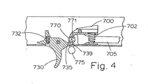
- Figure 4 is a cross-section similar to Figure 2C but with the sear actuator rotated to prevent operation of the trigger.
- In the Figures like reference numerals denote like parts.
- The gas operated automatic gun shown in Figure 1 has a
receiver 1 to therear wall channel 131 of which is connected abuttstock 2 and at the opposite end of thereceiver 1 from thebuttstock 2 there is connected abarrel 10. Apistol grip 11 is connected by a screw and nut underneath -thereceiver 1 and afore grip 12 is connected by screws on the underside of thebarrel 10. Thepistol grip 11 is connected to thereceiver 1 through the intermediary of atrigger guard 72 shrouding atrigger assembly 73 having a rotatable sear actuator (safety catch) 77. - Mounted in the bottom well of the
receiver 1 is a cartridge magazine 4 which is of the drum type although it may be a flat box-type magazine. The magazine 4 is held to the receiver by amagazine latch assembly 5. - A
cocking handle assembly 6 for a bolt carrier assembly (not shown) is mounted on the left hand side of the receiver l incorporating acocking bar sub-assembly 60 including acocking handle 601. - Mounted on the top rear of the
receiver 1 is arear sight mount 96 and on the right hand side of the receiver is acarrying handle 97. Also on the right hand side of the receiver is anejector slot 104 and in both sides at the front of the receiver are provided fourcooling apertures 105 to assist in removing heat from the rear end of thebarrel 10. A gas system-9 is connected in between the front of thereceiver 1 and aforesight assembly 95. Abayonet lug attachment 98 is provided on the barrel and at the muzzle there is aflash suppressor 99. - Turning now to Figures 2A to 4, the
trigger assembly 73 has an arcuatefinger pull trigger 730 pivotally mounted on a rod 73.1, thetrigger 730 being biassed by aspring 732 acting in ablind hole 736 within thetrigger 730 with one end of thespring 732 against the closure of theblind hole 736 and the other end of the spring against atrigger spring retainer 733 which is stationary with respect to the receiver. Theretainer 733 is located in a guide slot 734 in the trigger. A toprear face 735 of thetrigger 730 acts against the conventionally suppliedsear assembly 7 through the intermediary of asear actuator 77. Thesear actuator 77 has ahollow cylinder 770 which extends between the major walls of the receiver and slidingly mounted across the axis of the cylinder is anactuator 771 which is spring biassed toward the trigger toprear face 735. Thesear assembly 7 has asear 700 pivotally mounted on atransverse rod 701 which passes through the side limits of a U-shapedsear buffer 705 into opposing side walls of the receiver. Thesear 700 is biassed into a non-firing position by acompression spring 702 located between arecess 703 in thesear 700 and astud 704 mounted on the base of the receiver. - The partial view of Figure 2A shows the
receiver 1,trigger assembly 73, trigger 730 the sear actuator orsafety catch 77, and themagazine latch assembly 5. - Referring now to Figures 2B and 2C the
trigger assembly 73 has an arcuatefinger pull trigger 730 pivotally mounted on therod 731, thetrigger 730 being biassed by thespring 732 disposed in ablind hole 736 within thetrigger 730, one end of thespring 732 acting against the closure of theblind hole 736 and the other end of the spring acting against thetrigger spring retainer 733 which is stationary in respect to the receiver. Theretainer 733 is located in a guide slot 734 in the trigger to permit the trigger to move arcuately. The trigger has acentral portion 737 and twowings 738, therod 731 passing through thewings 738 into the receiver side walls. The trigger has atail 739 on which is provided the toprear face 735 which operates thesear 700 through the intermediary of thesear actuator 77. Thesear 700 is pivotally mounted by thetransverse rod 701 onto thebuffer 705 and thesear 700 is biassed in an anti-clockwise direction (as viewed in Figure 2C), by thecompression spring 702 which is located on thestud 704, secured to the base of the receiver, and in therecess 703 in the sear. - The actuator 77 (shown in Figures 2A - 2D) has a
lever 775 connected to thehollow cylinder 770 which extends between the side walls of thereceiver 1 and slidingly mounted across the axis of the cylinder is theactuator 771 having a circular cross-section. Theactuator 771 is biassed downwardly toward thetrigger tail 739 by acantilever spring 772 which is secured by fitting free ends of the spring in a cross bore in theactuator 771 and through a mutually perpendicular radial wall of thecylinder 770. Within the receiver, thecylinder 770 is provided with opposing non-parallelflat surfaces - In operation, with the
lever 775 horizontal and the trigger released, as shown in Figures 2A - 2D, thelip 712 of the sear abutting thesurface 773 is in parallel contact with thesurface 773 and theactuator 771 is biassed downwardly byspring 772 to abut the trigger toprear face 735 which is out of contact and not parallel with thesurface 774, as shown in Figure 2D. When thetrigger 730 is pulled to the rear of the receiver, i.e., to the right as shown in the Figures 1, 2A to 2C and 4, then the trigger rotates against the force ofspring 732 and the trigger pushes theactuator 771 upwardly against the force ofspring 772 to the position shown in Figure 3 -so that the tail toprear surface 735 of the trigger is then in contact with and parallel withsurface 774 and theactuator 771 pushes againstlip 712 thereby rotating thesear 700 in a clockwise direction as viewed in Figure 2C against the pressure of biassingspring 702. The top rear of the sear is thus rotated out of the path of the sear contacting lugs (not shown) to permit the bolt carrier assembly (not shown) to move forwardly toward the firing position. - When the
lever 775 is rotated through 90 degrees anti-clockwise (as viewed in Figures 1, 2A, 2C) to the position shown in Figure 4 so theactuator 771 is rotated out of abutment from the trigger and the trigger tail toprear face 735 abut the full diameter circular portion of thecylinder 770. Thus, when attempt is made to pull the trigger it does not move since it is in contact only with thecylinder 770 and thus does not impart any force to the sear through theactuator 771, and thereby renders the sear inoperable. - The lower edge of the magazine latch assembly acts as a stop surface to limit rotation of the
selector 77 to a right angle by, in one direction aknob 777 abutting the assembly and in the other direction acorner 776 of thelever 775 abutting the assembly. However, in some embodiments it may be desirable for theselector 77 to have three predetermined positions and thecorner 776 is then removed to permit thelever 775 to rotate through 18cp with the predetermined positions being angularly spaced at 0°, 90° and 180°. - Attention is directed toward our co-pending Application Nos which relate to various other features of the gun as herein described.
Claims (6)
1. A sear actuator for a gun characterised by a rotatable member (770) extending between opposing walls of a receiver (1) of the gun and movable with said member through like angles of movement, a slidable rod (771) extending transversely to said member arranged such that in a first position (700) (Fig.2C) of the member said rod interconnects motion of the trigger (730) to the sear (700), and in a second position of the member (Fig.4) said rod is rotated so that the interconnection between trigger and sear is removed.
2. A sear actuator as claimed in Claim 1, characterised in that the rod (771) is positioned internally through said member (770).
3. A sear actuator as claimed in Claim 2, including a trigger (730) and a sear (700) characterised in that the rotatable member is a cylinder (770) having two non-parallel surfaces (773, 774) and said rod is slidable between said surfaces and arranged such that in said first position and the trigger is not in a firing position, an abutment face of the sear (712) is in parallel contact with one of said surfaces (773) and the rod (771) holds an abutment face of the trigger (735) out of contact with the other of said surfaces (774), and when the trigger is in a firing position the abutment face of the trigger (735) is in parallel contact with the said other of said surfaces (774) and the rod (771) moves the abutment face of the sear (712) out of contact with said one surface (773).
4. A sear actuator as claimed in Claim 3, characterised in that the rod (771) is biassed, in said first position, toward the trigger.
5. A sear actuator as claimed in Claim 4, characterised in that a cantilever spring (772) biasses said rod (774), said spring being located in the cylinder (770) with free ends of the spring mounted in mutually perpendicular holes in the cylinder and rod.
6. A gun including the sear actuator of any preceding claim.
Priority Applications (1)
| Application Number | Priority Date | Filing Date | Title |
|---|---|---|---|
| EP84106493A EP0125705A3 (en) | 1980-12-11 | 1980-12-11 | Sear actuator for a gun |
Applications Claiming Priority (1)
| Application Number | Priority Date | Filing Date | Title |
|---|---|---|---|
| EP84106493A EP0125705A3 (en) | 1980-12-11 | 1980-12-11 | Sear actuator for a gun |
Related Parent Applications (2)
| Application Number | Title | Priority Date | Filing Date |
|---|---|---|---|
| EP80304481A Division EP0055307B1 (en) | 1980-12-11 | 1980-12-11 | Firearm |
| EP80304481.7 Division | 1980-12-11 |
Publications (2)
| Publication Number | Publication Date |
|---|---|
| EP0125705A2 true EP0125705A2 (en) | 1984-11-21 |
| EP0125705A3 EP0125705A3 (en) | 1984-12-19 |
Family
ID=8191972
Family Applications (1)
| Application Number | Title | Priority Date | Filing Date |
|---|---|---|---|
| EP84106493A Withdrawn EP0125705A3 (en) | 1980-12-11 | 1980-12-11 | Sear actuator for a gun |
Country Status (1)
| Country | Link |
|---|---|
| EP (1) | EP0125705A3 (en) |
Cited By (1)
| Publication number | Priority date | Publication date | Assignee | Title |
|---|---|---|---|---|
| EP3822573A1 (en) * | 2019-11-18 | 2021-05-19 | Rade Tecnologías, S. L. | Safety devices for firing weapons |
Family Cites Families (2)
| Publication number | Priority date | Publication date | Assignee | Title |
|---|---|---|---|---|
| DE445598C (en) * | 1924-10-17 | 1927-06-15 | Zbrojovka Praga Spol S R O | Trigger device for firearms |
| IT1103524B (en) * | 1978-02-24 | 1985-10-14 | Beretta Armi Spa | SAFETY DEVICE FOR GUNS WITH AUTOMATIC DOG RELEASE |
-
1980
- 1980-12-11 EP EP84106493A patent/EP0125705A3/en not_active Withdrawn
Cited By (2)
| Publication number | Priority date | Publication date | Assignee | Title |
|---|---|---|---|---|
| EP3822573A1 (en) * | 2019-11-18 | 2021-05-19 | Rade Tecnologías, S. L. | Safety devices for firing weapons |
| US11215415B2 (en) | 2019-11-18 | 2022-01-04 | Rade Tecnologias, S.L. | Safety devices for firing weapons |
Also Published As
| Publication number | Publication date |
|---|---|
| EP0125705A3 (en) | 1984-12-19 |
Similar Documents
| Publication | Publication Date | Title |
|---|---|---|
| GB2092721A (en) | Sear actuator for a gun | |
| US4475437A (en) | Sear actuator | |
| US10514223B1 (en) | Firearm trigger mechanism | |
| US4505182A (en) | Firearm trigger mechanism | |
| US4502367A (en) | Firearms bolt carrier assembly | |
| US3306168A (en) | Gas operated semi-automatic pistol | |
| US4358986A (en) | Rifle bolt assemblies | |
| US4522105A (en) | Firing mechanism for semiautomatic firearms | |
| US4523509A (en) | Shoulder arm | |
| US3279114A (en) | Grenade launcher | |
| US3724325A (en) | Rate reducer | |
| US10077961B2 (en) | Striker system for firearms | |
| US20200025488A1 (en) | Electronic operating mechanism for a firearm | |
| US4522106A (en) | Gun hammer mechanism | |
| SK212192A3 (en) | Hand fire arm | |
| US4151782A (en) | Handgun with indexing means | |
| US4467698A (en) | Angular shape firing pin for use with a collapsible toggle recoil in a hand held weapon | |
| US5223649A (en) | Apparatus and method for preventing accidental firing of a weapon | |
| US2512638A (en) | Fire control selector for automatic firearms | |
| US3709091A (en) | Adjustable hesitation blow back operated gun toggle mechanism | |
| EP0125705A2 (en) | Sear actuator for a gun | |
| US3242607A (en) | Firearm firing mechanism, especially for revolvers | |
| US3188763A (en) | Bolt action pistol | |
| US3276158A (en) | Firing mechanism for break-action over and under firearm | |
| US2775835A (en) | Bolt mechanism for firearm |
Legal Events
| Date | Code | Title | Description |
|---|---|---|---|
| PUAI | Public reference made under article 153(3) epc to a published international application that has entered the european phase |
Free format text: ORIGINAL CODE: 0009012 |
|
| PUAL | Search report despatched |
Free format text: ORIGINAL CODE: 0009013 |
|
| AC | Divisional application: reference to earlier application |
Ref document number: 55307 Country of ref document: EP |
|
| AK | Designated contracting states |
Designated state(s): AT BE CH DE FR IT LI LU NL SE |
|
| AK | Designated contracting states |
Designated state(s): AT BE CH DE FR IT LI LU NL SE |
|
| STAA | Information on the status of an ep patent application or granted ep patent |
Free format text: STATUS: THE APPLICATION IS DEEMED TO BE WITHDRAWN |
|
| 18D | Application deemed to be withdrawn |
Effective date: 19850820 |
|
| RIN1 | Information on inventor provided before grant (corrected) |
Inventor name: SULLIVAN, LEROY JAMES |