EP0125218A2 - Linearisierter Wanderfeldröhrenverstärker mit Hartbegrenzungseigenschaften - Google Patents
Linearisierter Wanderfeldröhrenverstärker mit Hartbegrenzungseigenschaften Download PDFInfo
- Publication number
- EP0125218A2 EP0125218A2 EP84850040A EP84850040A EP0125218A2 EP 0125218 A2 EP0125218 A2 EP 0125218A2 EP 84850040 A EP84850040 A EP 84850040A EP 84850040 A EP84850040 A EP 84850040A EP 0125218 A2 EP0125218 A2 EP 0125218A2
- Authority
- EP
- European Patent Office
- Prior art keywords
- twt
- spacing
- traveling wave
- efficiency
- slow wave
- Prior art date
- Legal status (The legal status is an assumption and is not a legal conclusion. Google has not performed a legal analysis and makes no representation as to the accuracy of the status listed.)
- Withdrawn
Links
Images
Classifications
-
- H—ELECTRICITY
- H01—ELECTRIC ELEMENTS
- H01J—ELECTRIC DISCHARGE TUBES OR DISCHARGE LAMPS
- H01J23/00—Details of transit-time tubes of the types covered by group H01J25/00
- H01J23/16—Circuit elements, having distributed capacitance and inductance, structurally associated with the tube and interacting with the discharge
- H01J23/24—Slow-wave structures, e.g. delay systems
Definitions
- This invention relates to traveling wave amplifying tubes wherein a traveling electromagnetic wave and an electron beam interact to effect amplification of a radiofrequency signal.
- United States Patent No. 3,668,544 to Lien discloses a slow wave tube wherein the signal to be amplified and a harmonid thereof are applied concurrently over at least a portion of the slow wave circuit to increase the RF conversion efficiency of the tube.
- United States Patent No. 3,809,949 to Scott discloses a vane loaded helix derived slow wave circuit wherein the degree of penetration of the vanes into the slow wave circuit is increased at the output end of the tube for introducing a frequency dependent velocity taper to increase efficiency of the tube.
- Winslow employs a helical structure that is loaded by placing longitudinal vanes or conductors around the helix adjacent its output end. The conductors are arranged such that the spacing from the conductor to the slow wave circuit decreases in a direction toward the collector.
- the Winslow structure increases the efficiency and the band width of a traveling wave tube but does not improve linearity.
- United States Patent No. 4,107,572 to Yuasa et al discloses a traveling wave tube having a slow wave circuit consisting of a constant phase velocity section and a tapering phase velocity section serially arranged between an attenuator and the output of the slow wave circuit.
- a particular ratio between the lengths of the constant tapering sections is prescribed for the purpose of improving the tube efficiency.
- United States Patent No. 3,972,005 to Nevins, Jr. et al discloses a traveling wave tube having a conductive circuit loading structure surrounding a helix slow wave circuit and extending for at least half the length of the helix and preferably for its entire length.
- the conductive circuit loading structure comprises a plurality of conductors disposed around the helix and arranged to conduct current associated with the radial frequency fields substantially only in the radial or axial direction of the helix and not in the circumferential direction. Such an arrangement results in an ultra wide band, high efficiency traveling wave tube.
- United States Patent No. 3,758,811 to Wong is concerned with the reduction of intermodulation products, which reduction may be achieved by increased linearity of operation of a traveling wave tube.
- the slow wave structure of Wong's traveling wave tube comprises a helix divided into three sections. The first section is a slow velocity and attenuator circuit, the second section is a positive velocity step producer, and the third section is a fast velocity circuit section having less pitch than the first section. Wong applies a positive velocity taper abruptly to the traveling wave.
- a dynamic velocity taper for a traveling wave tube.
- the taper begins at a point on the tube slow wave structure at which efficiency begins to become greater than about 0.1% and extends in a downstream direction toward a collector electrode to the point at which the output signal is picked off the slow wave circuit.
- the dynamic velocity taper is achieved by gradually reducing the spacing between repeating elements of the slow wave structure over a prescribed distance.
- the reduction in spacing between the slow wave structure repeating elements starts at about 0.1% and increases to about 5%.
- the reduction in spacing is at an exponential rate.
- the dynamic velocity taper maintains an optimum phase relationship between the traveling wave of the slow wave structure and bunches of electrons in the electron beam. Since a computed reduction in energy of the electron bunch is used to determine the phase velpsity of the slow wave circuit, it is thus dynamically matched to the rate of loss of energy.
- the desired dynamic velocity taper may be precomputed and a slow wave structure designed accordingly, following the computer outputs.
- the use of the dynamic velocity taper in accordance with the present invention provides for a traveling wave tube a characteristic that approaches that of an ideal hard limiter.
- the linearity of a traveling wave tube is greatly increased and the efficiency is also increased by a factor of about 1.1 to 1.5.
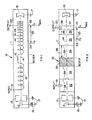
- a traveling wave tube 10 comprises an envelope 11 with an electron emitting cathode 12 and an accelerating anode 13 at one end. Electrons emitted by cathode 12 are accelerated by the anode 13 and are formed into a beam 14 which is collected at the other end of envelope 11 by a collector 15. The beam 14 is prevented from expanding due to a magnetic field from a solenoid (not shown) or permanent magnets coaxial with the envelope 11 as is common practice with traveling wave tubes having a helical slow wave structure (SWS).
- SWS helical slow wave structure
- Cathode 12 is maintained at a negative potential with respect to the anode 13 and the collector 15 by means of a DC source 16, the negative side of which is connected to the cathode 12, the positive side being connected to ground as at 17.
- the anode 13 and the collector 15 are grounded as at 17 and, accordingly, are positive with respect to cathode 12.
- a heater (not shown) is normally provided for cathode 12 to cause electron emission.
- the slow wave structure of TWT 10 comprises a helix 18 in which the turns may be considered as repeating structural elements.
- a signal input terminal 19 is connected to the end of the helix closest to the cathode 12 at one end of envelope 11 while an output terminal 20 is connected to the helix 18 either at its end or at a point slightly upstream of its end which is adjacent collector 15.
- One or more severs 21 may be provided for the helix in a manner well-known in the prior art.
- Important reference points on the helix 18 are identified by the line 23 representing the point Z at which efficiency of the TWT 10 is approximately 0.1% and line 22 representing the point Z s at which the output signal is taken off by terminal 20.
- the double ended arrow 25 indicates the axial distance between Z and Z over which o s the axial spacing 26 between adjacent structural elements such as the windings of helix 18 is reduced.
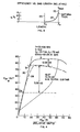
- the vertical lines 22 and 23 represent the same slow wave structure axial points which they delineate in Fig. 1. As shown by the curve 27, efficiency increases exponentially from about 0.1% at Z 0 to about 5% at Z which represents the output point of the helix 18 in Fig. 1. Vertical line 22 corresponds to the output point of the helix which is the point of maximum efficiency at which saturation occurs.
- curve 28 represents conventional TWT output power or efficiency vs. input power.
- a traveling wave amplifier tube in order to avoid intermodulation where a plurality of RF signals are being amplified, a traveling wave amplifier tube must be operated only in its linear region.
- the curve 28 is linear only up to approximately point 29. Thus, operation of the tube would have to be backed off to point 29, greatly reducing output efficiency and power.
- Curve 30 is a graph of output efficiency or output power vs. power input for a traveling wave tube embodying the invention. This curve is linear up to approximately the point 31 and closely approximates the curve of a hard limiter. Accordingly, a TWT embodying the invention has very high linearity and higher efficiency for certain rates of reduction of repeating element spacing.
- the components corresponding to those shown in Fig. 1 are identified by the same numerals.
- Such components include the envelope 11, cathode 12, anode 13, electron beam 14, collector 15, DC source 16, the common grounds 17, input terminal 19, output terminal 20, and a sever 21.
- cavities 32 through 37 are formed by a plurality of axially spaced discs 38.
- the discs 38 have central apertures to allow for passage of the electron beam 14 and are perpendicular to the long axis of the envelope 11.
- cavity 37 is smaller than that of 36 which, in turn, is smaller than that of 35, with 35 having a smaller axial length than cavity 34.
- Cavities 32, 33 and 34 all have the same axial length which is determined by the spacing between the discs 38 as indicated by the double ended arrow 39.
- the axial spacing of discs 38 decreases after point Z o to form the cavities 35-37.
- the spacing between the discs 38, the repeating elements is greatly exaggerated for purposes of illustration. In an actual coupled cavity tube, there would be many more cavities and the reduction in spacing between the repeating elements would be much less drastic and would be at a rate of reduction between 0.1% and 5% between Z and 0 Z , the decrease being preferably at an exponential rate s to obtain maximum linearity.
Landscapes
- Microwave Tubes (AREA)
- Microwave Amplifiers (AREA)
Applications Claiming Priority (2)
| Application Number | Priority Date | Filing Date | Title |
|---|---|---|---|
| US49252283A | 1983-05-09 | 1983-05-09 | |
| US492522 | 1983-05-09 |
Publications (2)
| Publication Number | Publication Date |
|---|---|
| EP0125218A2 true EP0125218A2 (de) | 1984-11-14 |
| EP0125218A3 EP0125218A3 (de) | 1986-04-09 |
Family
ID=23956601
Family Applications (1)
| Application Number | Title | Priority Date | Filing Date |
|---|---|---|---|
| EP84850040A Withdrawn EP0125218A3 (de) | 1983-05-09 | 1984-02-07 | Linearisierter Wanderfeldröhrenverstärker mit Hartbegrenzungseigenschaften |
Country Status (6)
| Country | Link |
|---|---|
| EP (1) | EP0125218A3 (de) |
| JP (1) | JPS59211939A (de) |
| AU (1) | AU549821B2 (de) |
| CA (1) | CA1219672A (de) |
| IL (1) | IL70857A (de) |
| IN (1) | IN159225B (de) |
Cited By (2)
| Publication number | Priority date | Publication date | Assignee | Title |
|---|---|---|---|---|
| EP0883154A1 (de) * | 1997-06-05 | 1998-12-09 | Hughes Electronics Corporation | Effiziente, hochlineare Wanderfeldröhre mit einem Kollektor mit hoher Rückstrom unter Sättigungsantrieb |
| EP3347983A1 (de) * | 2015-10-23 | 2018-07-18 | Airbus Defence and Space Limited | Hochleistungsverstärker |
Family Cites Families (5)
| Publication number | Priority date | Publication date | Assignee | Title |
|---|---|---|---|---|
| JPS53135259A (en) * | 1977-04-28 | 1978-11-25 | Nec Corp | Traveling-wave tube with phase-speed decelerating means in slow-wave circui t |
| FR2460539A1 (fr) * | 1979-07-03 | 1981-01-23 | Thomson Csf | Ligne a retard a pas variable pour tube a onde progressive, et tube a onde progressive muni d'une telle ligne |
| FR2468992A1 (fr) * | 1979-10-30 | 1981-05-08 | Thomson Csf | Ligne a retard a resistance de couplage variable, pour tube a champs croises et tube a champs croises comportant une telle ligne. |
| US4315194A (en) * | 1980-02-20 | 1982-02-09 | The United States Of America As Represented By The Administrator Of The National Aeronautics And Space Administration | Coupled cavity traveling wave tube with velocity tapering |
| FR2490872A1 (fr) * | 1980-09-19 | 1982-03-26 | Thomson Csf | Ligne a retard a cavites couplees pour tube a ondes progressives et tube a ondes progressives comportant une telle ligne |
-
1984
- 1984-01-25 CA CA000446021A patent/CA1219672A/en not_active Expired
- 1984-01-26 AU AU23822/84A patent/AU549821B2/en not_active Ceased
- 1984-02-02 IL IL70857A patent/IL70857A/xx not_active IP Right Cessation
- 1984-02-03 JP JP59017230A patent/JPS59211939A/ja active Pending
- 1984-02-07 EP EP84850040A patent/EP0125218A3/de not_active Withdrawn
- 1984-02-17 IN IN103/MAS/84A patent/IN159225B/en unknown
Cited By (3)
| Publication number | Priority date | Publication date | Assignee | Title |
|---|---|---|---|---|
| EP0883154A1 (de) * | 1997-06-05 | 1998-12-09 | Hughes Electronics Corporation | Effiziente, hochlineare Wanderfeldröhre mit einem Kollektor mit hoher Rückstrom unter Sättigungsantrieb |
| EP3347983A1 (de) * | 2015-10-23 | 2018-07-18 | Airbus Defence and Space Limited | Hochleistungsverstärker |
| US10693427B2 (en) | 2015-10-23 | 2020-06-23 | Airbus Defence And Space Limited | High-efficiency amplifier |
Also Published As
| Publication number | Publication date |
|---|---|
| JPS59211939A (ja) | 1984-11-30 |
| IN159225B (de) | 1987-04-11 |
| AU549821B2 (en) | 1986-02-13 |
| AU2382284A (en) | 1984-11-15 |
| CA1219672A (en) | 1987-03-24 |
| IL70857A (en) | 1986-12-31 |
| IL70857A0 (en) | 1984-05-31 |
| EP0125218A3 (de) | 1986-04-09 |
Similar Documents
| Publication | Publication Date | Title |
|---|---|---|
| US4564787A (en) | Linearized traveling wave amplifier with hard limiter characteristics | |
| US3207943A (en) | High frequency tube method and apparatus | |
| EP0125218A2 (de) | Linearisierter Wanderfeldröhrenverstärker mit Hartbegrenzungseigenschaften | |
| US3571651A (en) | Log periodic electron discharge device | |
| US2851630A (en) | High power traveling-wave tube | |
| US4087718A (en) | High gain crossed field amplifier | |
| US5521551A (en) | Method for suppressing second and higher harmonic power generation in klystrons | |
| US5162697A (en) | Traveling wave tube with gain flattening slow wave structure | |
| US4168451A (en) | Multi-cavity klystron amplifiers | |
| US5942852A (en) | Efficient, highly linear traveling wave tube using collector with high backstreaming current under saturated drive | |
| Srivastava et al. | Determination of sever positions in coupled-cavity TWTs | |
| Scott | Why a circuit sever affects traveling-wave tube efficiency | |
| US3289032A (en) | Microwave hybrid tube apparatus | |
| US3940654A (en) | Traveling wave tube having tapered longitudinally directed loading conductors at the output | |
| Jung | 10 KW and up from a helix TWT? | |
| Malsaria et al. | Simulation of Beam Wave Interaction for a helix space TWT's | |
| Pond et al. | Improvement of traveling-wave tube efficiency through period tapering | |
| US3924152A (en) | Electron beam amplifier tube with mismatched circuit sever | |
| US3668544A (en) | High efficiency traveling wave tube employing harmonic bunching | |
| EP0352961A1 (de) | Klystrode-Frequenzvervielfacher | |
| Bates et al. | The effect of circuit tapering on the efficiency bandwidth characteristics of dispersive traveling-wave tubes | |
| Putz et al. | Use of multiple-helix circuits in 100-watt traveling-wave amplifiers | |
| Rogovin et al. | Investigation of rods shapes and materials influence on Q-band travelling wave tube high frequency characteristics | |
| US4376908A (en) | Impedance tapered dematron | |
| RU2076383C1 (ru) | Электровакуумный прибор свч типа "о" с сосредоточенным взаимодействием |
Legal Events
| Date | Code | Title | Description |
|---|---|---|---|
| PUAI | Public reference made under article 153(3) epc to a published international application that has entered the european phase |
Free format text: ORIGINAL CODE: 0009012 |
|
| AK | Designated contracting states |
Designated state(s): BE CH DE FR GB IT LI NL SE |
|
| PUAL | Search report despatched |
Free format text: ORIGINAL CODE: 0009013 |
|
| AK | Designated contracting states |
Kind code of ref document: A3 Designated state(s): BE CH DE FR GB IT LI NL SE |
|
| 17P | Request for examination filed |
Effective date: 19860624 |
|
| 17Q | First examination report despatched |
Effective date: 19871012 |
|
| STAA | Information on the status of an ep patent application or granted ep patent |
Free format text: STATUS: THE APPLICATION IS DEEMED TO BE WITHDRAWN |
|
| 18D | Application deemed to be withdrawn |
Effective date: 19880423 |
|
| RIN1 | Information on inventor provided before grant (corrected) |
Inventor name: KOSMAHL, HENRY GOTTLOB |