EP0124792B1 - Nozzle assembly - Google Patents
Nozzle assembly Download PDFInfo
- Publication number
- EP0124792B1 EP0124792B1 EP84104016A EP84104016A EP0124792B1 EP 0124792 B1 EP0124792 B1 EP 0124792B1 EP 84104016 A EP84104016 A EP 84104016A EP 84104016 A EP84104016 A EP 84104016A EP 0124792 B1 EP0124792 B1 EP 0124792B1
- Authority
- EP
- European Patent Office
- Prior art keywords
- nozzle
- reservoir
- mounting surface
- molten metal
- force
- Prior art date
- Legal status (The legal status is an assumption and is not a legal conclusion. Google has not performed a legal analysis and makes no representation as to the accuracy of the status listed.)
- Expired
Links
- 239000002184 metal Substances 0.000 claims description 55
- 238000005266 casting Methods 0.000 claims description 16
- 238000006073 displacement reaction Methods 0.000 claims description 15
- 238000007789 sealing Methods 0.000 claims description 9
- 239000012530 fluid Substances 0.000 claims description 6
- 230000013011 mating Effects 0.000 claims description 5
- 238000004891 communication Methods 0.000 claims description 4
- 238000010438 heat treatment Methods 0.000 claims description 2
- 238000000034 method Methods 0.000 claims description 2
- 238000010791 quenching Methods 0.000 description 6
- 230000035882 stress Effects 0.000 description 6
- 239000007789 gas Substances 0.000 description 4
- VYPSYNLAJGMNEJ-UHFFFAOYSA-N Silicium dioxide Chemical compound O=[Si]=O VYPSYNLAJGMNEJ-UHFFFAOYSA-N 0.000 description 2
- 230000000712 assembly Effects 0.000 description 2
- 238000000429 assembly Methods 0.000 description 2
- 238000001125 extrusion Methods 0.000 description 2
- 239000005300 metallic glass Substances 0.000 description 2
- 230000002093 peripheral effect Effects 0.000 description 2
- 230000008646 thermal stress Effects 0.000 description 2
- 238000003466 welding Methods 0.000 description 2
- PZNSFCLAULLKQX-UHFFFAOYSA-N Boron nitride Chemical compound N#B PZNSFCLAULLKQX-UHFFFAOYSA-N 0.000 description 1
- 239000000853 adhesive Substances 0.000 description 1
- 230000001070 adhesive effect Effects 0.000 description 1
- 229910045601 alloy Inorganic materials 0.000 description 1
- 239000000956 alloy Substances 0.000 description 1
- PNEYBMLMFCGWSK-UHFFFAOYSA-N aluminium oxide Inorganic materials [O-2].[O-2].[O-2].[Al+3].[Al+3] PNEYBMLMFCGWSK-UHFFFAOYSA-N 0.000 description 1
- 229910000808 amorphous metal alloy Inorganic materials 0.000 description 1
- 239000000919 ceramic Substances 0.000 description 1
- 230000006835 compression Effects 0.000 description 1
- 238000007906 compression Methods 0.000 description 1
- 238000009749 continuous casting Methods 0.000 description 1
- 230000009977 dual effect Effects 0.000 description 1
- 239000000835 fiber Substances 0.000 description 1
- 239000011261 inert gas Substances 0.000 description 1
- 230000001788 irregular Effects 0.000 description 1
- 239000007788 liquid Substances 0.000 description 1
- 238000003754 machining Methods 0.000 description 1
- 238000004519 manufacturing process Methods 0.000 description 1
- 239000000463 material Substances 0.000 description 1
- 229910001092 metal group alloy Inorganic materials 0.000 description 1
- 239000011819 refractory material Substances 0.000 description 1
- 230000001105 regulatory effect Effects 0.000 description 1
- 239000000377 silicon dioxide Substances 0.000 description 1
- 238000004804 winding Methods 0.000 description 1
Images


Classifications
-
- B—PERFORMING OPERATIONS; TRANSPORTING
- B22—CASTING; POWDER METALLURGY
- B22D—CASTING OF METALS; CASTING OF OTHER SUBSTANCES BY THE SAME PROCESSES OR DEVICES
- B22D11/00—Continuous casting of metals, i.e. casting in indefinite lengths
- B22D11/06—Continuous casting of metals, i.e. casting in indefinite lengths into moulds with travelling walls, e.g. with rolls, plates, belts, caterpillars
- B22D11/0637—Accessories therefor
- B22D11/064—Accessories therefor for supplying molten metal
- B22D11/0642—Nozzles
-
- B—PERFORMING OPERATIONS; TRANSPORTING
- B22—CASTING; POWDER METALLURGY
- B22D—CASTING OF METALS; CASTING OF OTHER SUBSTANCES BY THE SAME PROCESSES OR DEVICES
- B22D11/00—Continuous casting of metals, i.e. casting in indefinite lengths
- B22D11/10—Supplying or treating molten metal
Definitions
- the invention relates to an apparatus for casting metal strip. More particularly, the invention relates to a nozzle assembly system for mounting a casting nozzle to a crucible reservoir to cast continuous metal strip.
- molten metal has typically been extruded from a pressurized reservoir through a nozzle on to a high speed, rotating quench surface.
- Representative apparatus are shown in US-A-4 142 571.
- the sealing means of the US-A-4 154 380 is comprised of a tapered, frusta-conical surface on the casting nozzle which is adapted to mate with a corresponding tapered surface along the outlet passage from the crucible.
- the weight of the nozzle plus the metallostatic pressure head holds the mated, tapered surfaces together.
- These tapered surfaces require precise machining to obtain the required degree of sealing effectiveness.
- the closely mated surfaces do not allow for any differences in thermal expansion between the crucible and the nozzle body, particularly where the crucible and nozzle body are constructed from different refractory materials having different coefficients of thermal expansion.
- the nozzle can expand more than the crucible outlet passage opening, and very large lateral, side to side, forces developed between the crucible and nozzle have often caused the nozzle to fracture. If the nozzle should fracture severely, the flow of molten metal is no longer restricted by the relatively small nozzle extrusion orifice; large volumes of molten metal may then escape and damage the casting surface and any nearby auxiliary support equipment.
- the invention provides an apparatus for casting continuous metal strip comprising:
- the invention advantageously allows differential thermal expansion between the nozzle body and reservoir.
- the lateral clearance avoids lateral contact between the nozzle and reservoir, and the planar mounting surfaces allow an amount of relative movement along the mated, parallel mounting surfaces to avoid the build up of excessive lateral stresses that could fracture the nozzle or crucible.
- the force means which resiliently urges the nozzle and reservoir means together, allows a lengthwise, longitudinal thermal expansion of the nozzle without a buildup of excessive internal stresses.
- the safety device prevents a sudden escape of excessive amounts of molten metal if the nozzle should become inadvertently fractured.
- the present inveniton more reliably and more efficiently casts continuous metal strip.
- the invention minimizes nozzle fracturing due to thermal stresses developed between the nozzle and the reservoir means and minimizes the escape of molten metal from the reservoir if the nozzle should become inadvertently fractured.
- the present invention is suitable for casting continuous strip of crystalline or amorphous metal. While the preferred embodiments are described with respect to casting amorphous metal alloy strip, it is readily apparent that the invention can be easily adapted to cast crystalline metal strip as well.
- a “strip” is a slender body in which the transverse dimensions are much smaller than the length.
- a strip includes wire, ribbon and sheet of regular or irregular cross-section.
- FIG. 1 shows a typical prior art apparatus for the continuous casting of metal strip to point out the general use of the present invention.
- Molten alloy contained in crucible 101 is heated with a heating element 4.
- Pressurization of the crucible with an inert gas extrudes a stream of molten metal from nozzle 102, located at the base of the crucible, onto quench surface 5 of rotating quench wheel 6.
- the solidified moving strip 8 after its break-away point from the quench wheel is routed onto a winding wheel (not shown).
- the extruded metal is quenched at an extremely rapid rate of at least about 10 4 °C/sec, and the solidified strip moves rapidly off the quench wheel at a speed ranging from about 400-2200 m/min.
- the cast strip is quite thin, typically about 25-100 microns thick, but considerable selectivity may be exercised with respect to the width and cross-section.
- FIG. 2 shows a representative nozzle assembly for casting continuous metal strip in which a nozzle means for extruding molten metal is shown generally at 2.
- the nozzle has a nozzle body 12, a nozzle inlet opening shown generally at 14, a nozzle exit orifice 16 and a nozzle mounting surface, such as substantially planar surface 24.
- a reservoir means, comprised of crucible 1, contains molten metal and includes a reservoir outlet opening, shown generally at 10, for flowing the molten metal therethrough.
- a reservoir mounting surface, such as substantially planar surface 22, is located on the reservoir means proximate to the reservoir outlet.
- Reservoir surface 22 is adapted to mate with nozzle surface 24 and allow a relative, sliding-type movement therebetween due to a differing thermal expansion of nozzle 2 relative to crucible 1.
- the reservoir crucible is adapted to provide a lateral clearance distance 3 between nozzle 2 and crucible 1. The lateral clearance prevents lateral contact caused by a differing thermal expansion of nozzle 2 relative to crucible 1.
- a safety device is comprised of a cover member 26 having a constricted passage 28 therethrough. Cover 26 has a peripheral, outwardly extending cover flange 29 adapted to mount at the inlet portion 14 of nozzle 2 to limit the flow of molten metal from crucible 1 into the nozzle.
- a resilient, heat resistant sealing means such as a boron nitride paste adhesive 21, is interposed between nozzle mounting surface 24 and crucible mounting surface 22 to minimize molten metal leakage therebetween.
- Force means 30 resiliently urges the nozzle mounting surface toward the crucible mounting surface to mate the nozzle and crucible together.
- the apparatus of the invention advantageously minimizes any stresses caused by differing amounts of thermal expansion between nozzle 2 and crucible 1.
- lateral clearance 3 avoids lateral contact between the nozzle and crucible, and the planar mounting surfaces 22 and 24, disposed substantially parallel to each other, allows relatively free, sliding-type movement between the nozzle and the crucible. Surface shear stresses are present, but bulk stresses that could crack and break the nozzle are minimized.
- the resilient force means allows longitudinal thermal expansion while mating and holding together nozzle 2 and crucible 1 with a force sufficient to prevent molten metal leakage therebetween.
- the nozzle assembly illustrated in FIG. 2 is an internally mounted nozzle.
- the reservoir mounting surface is an inwardly facing surface 22 of crucible 1
- the nozzle mounting surface is a nozzle body surface 24 facing in the direction of the intended flow of molten metal.
- nozzle mounting surface 24 is located on a surface of a nozzle flange 15 which extends radially outward along a peripheral edge of nozzle body 12.
- force means 30 can be comprised of a distinct mechanical mechanism, the force means in this embodiment is preferably provided by the weight of nozzle 2 and cover 26 along with the metallostatic pressure head of any molten metal contained in crucible 1.
- FIG. 3 shows an externally mounted nozzle which compared to'the internally mounted nozzle is more easily removed and serviced, particularly when there is molten metal in crucible 1.
- a stopper rod 66 can be employed to block passage 28 while the nozzle is being preheated or serviced.
- the reservoir mounting surface is an outwardly facing surface 25 of crucible 1
- the nozzle mounting surface is a nozzle body surface 20 facing opposite to the direction of the intended flow of molten metal.
- nozzle mounting surface 20 facing opposite to the direction of the intended flow of molten metal.
- nozzle mounting surface 20 is located on a surface of nozzle flange 15 to increase the mated surface area between the nozzle and crucible.
- the sealing means 23 for the externally mounted nozzle is preferably comprised of a gasket composed of a ceramic fiber, such as alumina silica. Such a gasket is easier to handle than a paste material and still allows the needed amount of movement between planar surfaces 20 and 25.
- the externally mounted nozzle advantageously eliminates the need for a separate cover for the safety device.
- the cover member of the safety device is comprised of the bottom wall 64 of crucible 1, and constricted outlet passage 28 which communicates through bottom wall 64 limits the flow of molten metal from crucible 1.
- the externally mounted nozzle does require a force means 30 comprised of a distinct mechanical mechanism 33 to hold the nozzle and crucible together and maintain alignment therebetween.
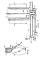
- FIG. 4 shows an embodiment of the invention which employs an optional nozzle heater means 18 disposed about nozzle 2 to preheat the nozzle and maintain the temperature of the molten metal as it passes therethrough.
- FIG. 4 further shows a force means comprised of springs.
- a support member such as frame 32
- a displacement member such as plate 34
- a displacement member such as plate 34
- Spring means are operably connected to plate 34 and support frame 32.
- Springs 36 provide a selected force which is adapted to move plate 34 toward nozzle 2 and resiliently urge the nozzle mounting surface 23 toward crucible mounting surface 25.
- Adjustment means comprised of threaded studs 38, nuts 42 and washers 40, adjust springs 36 to provide a selected spring force.
- threaded studs 38 are attached to frame 32 by suitable attachment means, such as welding.
- the studs extend through holes in plate 34 and are adapted to slide freely through those holes.
- frame 32 has openings which allow nozzle 2 and heater 18 to extend therethrough without interference from the frame. There is sufficient clearance between nozzle 2 and frame 32 to eliminate any lateral, side to side contact therebetween due to thermal expansion of the nozzle.
- Plate 34 is adapted to operably contact nozzle heater 18 and move nozzle 2 toward crucible 1.
- Plate 34 also has an opening 61 therethrough which is configured to allow extrusion of molten metal from nozzle 2 onto a suitable quench surface.
- a spring 36 and a washer 40 are assembled about each stud 38.
- Each spring is interposed between a washer 40 and the frame 32, and. nut 42 is then threaded onto each stud 38.
- plate 34 is drawn up against heater 18, which contacts nozzle 2 to urge the nozzle mating surface 23 toward crucible surface 25 and hold the nozzle and crucible together.
- the resilience of the springs also allows longitudinal movement of plate 32 along studs 38 in response to the thermal expansion of nozzle 2 and heater 18, and prevents the buildup of excessive stresses within the nozzle.
- the ambient high temperatures which can exceed 1,000°C, can cause a relaxation of the force exerted by springs 36.
- the force between nozzle 2 and crucible 1 may become too low to maintain an adequate seal therebetween, and leakage of molten metal may occur.
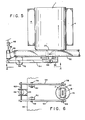
- the force means is preferably comprised of a pneumatic actuator mechanism as shown in Figures 5 and 6.
- a pneumatic actuator 46 operated by a pressurized fluid, such as compressed gas one can advantageously monitor and continuously adjust the gas pressure in the actuator to provide a substantially constant force that operates to hold nozzle 2 and crucible 1 together and maintains an adequate seal therebetween.
- support frame 32 is substantially immobile with respect to crucible 1 and has openings configured to accommodate placement of nozzle 2 and heater 18 therethrough without interference from the frame.
- a displacement member is comprised of lever arms 54, a cross member 52 connected between two end portions of the lever arms and a pivot plate 35. The displacement member is movable relative to frame 32.
- pivot means comprised of pivot brackets 52 and pivot bearings 56, connect to support frame 32 and are adapted to pivot the displacement means thereabout.
- Pivot brackets 52 are rigidly connected to support frame 32 by suitable fasteners or by welding and are adapted to support pivot bearings 56.
- Pivot bearings 56 pivotably connect each lever arm 54 to its respective pivot bracket 52.
- a pneumatic actuator means such as a dual action pneumatic actuator 46, is adapted to pivot the displacement member about the pivot means to move a portion of the displacement member, particularly plate 35, toward nozzle 2.
- Actuator 46 further provides a selected force that resiliently urges the nozzle mounting surface 23 toward mounting surface 25 of the crucible reservoir to mate and hold the nozzle and crucible together.
- actuator brackets 50 are rigidly connected to frame 32 and adapted to support actuator 46.
- Actuator 46 operably connects to cross member 62 and when operated, provides a force that moves cross member 62 downwards to pivot lever arms 54 about pivot pins 56. As the lever arms rotate, they move plate 35 upward against nozzle heater 18 which in turn, contacts nozzle 2.
- the preselected force provided by actuator 46 urges surface 23 toward surface 25 to mate the nozzle and crucible together.
- Pressure regulator means 48 controls the gas pressure supplied to actuator 46 to adjust the force directed against heater 18 and nozzle 2.
- the regulated gas pressure in actuator 46 provides a resiliency which allows thermal expansion of nozzle 2 and downward movement of plate 35 while still maintaining a constant, stable force between nozzle 2 and crucible 1 that is sufficient to preserve the liquid seal therebetween. As a result, leakage is minimized and excessive thermal stresses that could fracture the nozzle are avoided.
Landscapes
- Engineering & Computer Science (AREA)
- Mechanical Engineering (AREA)
- Continuous Casting (AREA)
Description
- The invention relates to an apparatus for casting metal strip. More particularly, the invention relates to a nozzle assembly system for mounting a casting nozzle to a crucible reservoir to cast continuous metal strip.
- In the production of continuous metal strip, molten metal has typically been extruded from a pressurized reservoir through a nozzle on to a high speed, rotating quench surface. Representative apparatus are shown in US-A-4 142 571.
- When continuously casting metal strip over extended periods of time, it has been desirable to connect a recplaceable nozzle to a separate crucible capable of holding a large quantity of molten metal. The resultant multipiece assembly has required sealing means to prevent leakage of molten metal between the component parts. A conventional nozzle assembly is representatively shown in US-A-4154 380 describing the nearest prior art to which the preambles of the
independent claims - The sealing means of the US-A-4 154 380 is comprised of a tapered, frusta-conical surface on the casting nozzle which is adapted to mate with a corresponding tapered surface along the outlet passage from the crucible. The weight of the nozzle plus the metallostatic pressure head holds the mated, tapered surfaces together. These tapered surfaces, however, required precise machining to obtain the required degree of sealing effectiveness. In addition, the closely mated surfaces do not allow for any differences in thermal expansion between the crucible and the nozzle body, particularly where the crucible and nozzle body are constructed from different refractory materials having different coefficients of thermal expansion. As a result, the nozzle can expand more than the crucible outlet passage opening, and very large lateral, side to side, forces developed between the crucible and nozzle have often caused the nozzle to fracture. If the nozzle should fracture severely, the flow of molten metal is no longer restricted by the relatively small nozzle extrusion orifice; large volumes of molten metal may then escape and damage the casting surface and any nearby auxiliary support equipment.
- Thus, conventional nozzle assemblies, such as those taught by US-A-4 154 380, have lacked a mechanism for preventing nozzle fracture due to thermal expansion of the nozzle against the crucible and have lacked a safety device to prevent the sudden escape of large volumes of molten metal from a fractured nozzle.
- The invention provides an apparatus for casting continuous metal strip comprising:
- (a) nozzle means for extruding molten metal, which has a nozzle body, a nozzle inlet opening, a nozzle exit orifice and a nozzle mounting surface located proximate to said nozzle inlet opening,
- (b) reservoir means in fluid communication with said nozzle means for containing said molten metal, said, reservoir means having a reservoir outlet opening for flowing said molten metal therethrough and having a reservoir mounting surface located proximate to said reservoir outlet and
- (c) sealing means located between said nozzle mounting surface and said reservoir mounting surface for minimizing molten metal leakage therebetween; and is characterized in that
- (d) said nozzle mounting surface mates with said reservoir mounting surface allowing a relative, sliding-type movement,
- (e) said sealing means are resilient and heat resistant; and
- (f) force means are provided for resiliently urging said nozzle mounting surface toward said reservoir mounting surface, while allowing longitudinal movement of the nozzle means relative to the reservoir means.
- In accordance with the invention, there is further provided a method for casting continuous . metal strip, comprising the steps of:
- (a) containing a supply of molten metal in a reservoir means which has a reservoir mounting surface located proximate to a reservoir outlet opening,
- (b) extruding said molten metal from a nozzle means which is in fluid communication with said reservoir means and has a nozzle mounting surface located proximate to a nozzle inlet opening, and
- (c) mating together said nozzle mounting surface with said reservoir mounting surface, the region between said surfaces being sealed to minimize molten metal leakage therebetween, which is characterized by
- (d) providing means to allow a relative, sliding-type movement between said nozzle and reservoir mounting surfaces due to a differing thermal expansion of said nozzle means relative to said reservoir means and
- (e) resiliently urging said nozzle mounting surface toward said reservoir mounting surface.
- The invention advantageously allows differential thermal expansion between the nozzle body and reservoir. In particular, the lateral clearance avoids lateral contact between the nozzle and reservoir, and the planar mounting surfaces allow an amount of relative movement along the mated, parallel mounting surfaces to avoid the build up of excessive lateral stresses that could fracture the nozzle or crucible. Additionally, the force means, which resiliently urges the nozzle and reservoir means together, allows a lengthwise, longitudinal thermal expansion of the nozzle without a buildup of excessive internal stresses. The safety device prevents a sudden escape of excessive amounts of molten metal if the nozzle should become inadvertently fractured.
- Thus, compared to conventional nozzle assemblies without planar mounting surfaces, without a resilient force means or without a safety device, the present inveniton more reliably and more efficiently casts continuous metal strip. The invention minimizes nozzle fracturing due to thermal stresses developed between the nozzle and the reservoir means and minimizes the escape of molten metal from the reservoir if the nozzle should become inadvertently fractured.
- The invention will be more fully understood and further advantages will become apparent when reference is made to the following detailed description of the preferred embodiment of the invention and the accompanying drawings in which:
- FIG. 1 shows a representative prior art apparatus for casting continuous metal strip;
- FIG. 2 shows a representative cross-sectional view of a nozzle mounted internally to a crucible;
- FIG. 3 shows a representative cross-sectional view of a nozzle mounted externally to a crucible;
- FIG. 4 shows a side elevational view of a nozzle mounted externally to a crucible with a force means comprised of springs;
- FIG. 5 shows a side elevational view of a nozzle mounted externally to a crucible with a forced means comprised of a pneumatic actuator;
- FIG. 6 shows a bottom plan view of the pneumatic actuator mechanism taken in the direction A-A of FIG. 5; and
- FIG. 7 shows a representative cross-sectional view of the apparatus shown in FIG. 5.
- The present invention is suitable for casting continuous strip of crystalline or amorphous metal. While the preferred embodiments are described with respect to casting amorphous metal alloy strip, it is readily apparent that the invention can be easily adapted to cast crystalline metal strip as well.
- For the purposes of the present invention and as used in the specification and claims, a "strip" is a slender body in which the transverse dimensions are much smaller than the length. Thus, a strip includes wire, ribbon and sheet of regular or irregular cross-section.
- FIG. 1 shows a typical prior art apparatus for the continuous casting of metal strip to point out the general use of the present invention. Molten alloy contained in
crucible 101 is heated with aheating element 4. Pressurization of the crucible with an inert gas extrudes a stream of molten metal fromnozzle 102, located at the base of the crucible, onto quench surface 5 of rotating quench wheel 6. The solidified movingstrip 8 after its break-away point from the quench wheel is routed onto a winding wheel (not shown). - When casting a strip of amorphous, glassy metal or when casting a strip of certain crystalline metal alloys, the extruded metal is quenched at an extremely rapid rate of at least about 104°C/sec, and the solidified strip moves rapidly off the quench wheel at a speed ranging from about 400-2200 m/min. The cast strip is quite thin, typically about 25-100 microns thick, but considerable selectivity may be exercised with respect to the width and cross-section.
- FIG. 2 shows a representative nozzle assembly for casting continuous metal strip in which a nozzle means for extruding molten metal is shown generally at 2. The nozzle has a
nozzle body 12, a nozzle inlet opening shown generally at 14, anozzle exit orifice 16 and a nozzle mounting surface, such as substantiallyplanar surface 24. A reservoir means, comprised ofcrucible 1, contains molten metal and includes a reservoir outlet opening, shown generally at 10, for flowing the molten metal therethrough. A reservoir mounting surface, such as substantiallyplanar surface 22, is located on the reservoir means proximate to the reservoir outlet.Reservoir surface 22 is adapted to mate withnozzle surface 24 and allow a relative, sliding-type movement therebetween due to a differing thermal expansion ofnozzle 2 relative tocrucible 1. In addition, the reservoir crucible is adapted to provide alateral clearance distance 3 betweennozzle 2 andcrucible 1. The lateral clearance prevents lateral contact caused by a differing thermal expansion ofnozzle 2 relative tocrucible 1. A safety device is comprised of acover member 26 having a constrictedpassage 28 therethrough.Cover 26 has a peripheral, outwardly extendingcover flange 29 adapted to mount at theinlet portion 14 ofnozzle 2 to limit the flow of molten metal fromcrucible 1 into the nozzle. A resilient, heat resistant sealing means, such as a boronnitride paste adhesive 21, is interposed betweennozzle mounting surface 24 andcrucible mounting surface 22 to minimize molten metal leakage therebetween. Force means 30 resiliently urges the nozzle mounting surface toward the crucible mounting surface to mate the nozzle and crucible together. - The apparatus of the invention advantageously minimizes any stresses caused by differing amounts of thermal expansion between
nozzle 2 andcrucible 1. In particular,lateral clearance 3 avoids lateral contact between the nozzle and crucible, and the planar mounting surfaces 22 and 24, disposed substantially parallel to each other, allows relatively free, sliding-type movement between the nozzle and the crucible. Surface shear stresses are present, but bulk stresses that could crack and break the nozzle are minimized. In addition, the resilient force means allows longitudinal thermal expansion while mating and holding togethernozzle 2 andcrucible 1 with a force sufficient to prevent molten metal leakage therebetween. - The nozzle assembly illustrated in FIG. 2 is an internally mounted nozzle. Thus, the reservoir mounting surface is an inwardly facing
surface 22 ofcrucible 1, and the nozzle mounting surface is anozzle body surface 24 facing in the direction of the intended flow of molten metal. Preferably,nozzle mounting surface 24 is located on a surface of anozzle flange 15 which extends radially outward along a peripheral edge ofnozzle body 12. While force means 30 can be comprised of a distinct mechanical mechanism, the force means in this embodiment is preferably provided by the weight ofnozzle 2 and cover 26 along with the metallostatic pressure head of any molten metal contained incrucible 1. - FIG. 3 shows an externally mounted nozzle which compared to'the internally mounted nozzle is more easily removed and serviced, particularly when there is molten metal in
crucible 1. Astopper rod 66 can be employed to blockpassage 28 while the nozzle is being preheated or serviced. In this embodiment, the reservoir mounting surface is an outwardly facingsurface 25 ofcrucible 1, and the nozzle mounting surface is anozzle body surface 20 facing opposite to the direction of the intended flow of molten metal. Preferably,nozzle mounting surface 20 facing opposite to the direction of the intended flow of molten metal. Preferably,nozzle mounting surface 20 is located on a surface ofnozzle flange 15 to increase the mated surface area between the nozzle and crucible. The sealing means 23 for the externally mounted nozzle is preferably comprised of a gasket composed of a ceramic fiber, such as alumina silica. Such a gasket is easier to handle than a paste material and still allows the needed amount of movement betweenplanar surfaces bottom wall 64 ofcrucible 1, and constrictedoutlet passage 28 which communicates throughbottom wall 64 limits the flow of molten metal fromcrucible 1. The externally mounted nozzle, however, does require a force means 30 comprised of a distinctmechanical mechanism 33 to hold the nozzle and crucible together and maintain alignment therebetween. - FIG. 4 shows an embodiment of the invention which employs an optional nozzle heater means 18 disposed about
nozzle 2 to preheat the nozzle and maintain the temperature of the molten metal as it passes therethrough. FIG. 4 further shows a force means comprised of springs. - In this embodiment of the invention, a support member, such as
frame 32, is configured to be substantially immobile with respect tocrucible 1. A displacement member, such asplate 34, is spaced a distance away fromsupport frame 32 and is movable relative to the frame. Spring means, such ascompressible springs 36, are operably connected to plate 34 andsupport frame 32.Springs 36 provide a selected force which is adapted to moveplate 34 towardnozzle 2 and resiliently urge thenozzle mounting surface 23 towardcrucible mounting surface 25. Adjustment means, comprised of threadedstuds 38,nuts 42 andwashers 40, adjustsprings 36 to provide a selected spring force. - As shown by FIG. 4, threaded
studs 38 are attached to frame 32 by suitable attachment means, such as welding. The studs extend through holes inplate 34 and are adapted to slide freely through those holes. Additionally,frame 32 has openings which allownozzle 2 andheater 18 to extend therethrough without interference from the frame. There is sufficient clearance betweennozzle 2 andframe 32 to eliminate any lateral, side to side contact therebetween due to thermal expansion of the nozzle.Plate 34 is adapted to operablycontact nozzle heater 18 and movenozzle 2 towardcrucible 1.Plate 34 also has anopening 61 therethrough which is configured to allow extrusion of molten metal fromnozzle 2 onto a suitable quench surface. Aspring 36 and awasher 40 are assembled about eachstud 38. Each spring is interposed between awasher 40 and theframe 32, and.nut 42 is then threaded onto eachstud 38. Thus, by selectively turningnuts 42 up ontostud 38 to compresssprings 36,plate 34 is drawn up againstheater 18, whichcontacts nozzle 2 to urge thenozzle mating surface 23 towardcrucible surface 25 and hold the nozzle and crucible together. By adjusting the amount of compression imparted tosprings 36, the amount of mating force can be adjusted to a selected magnitude. The resilience of the springs also allows longitudinal movement ofplate 32 alongstuds 38 in response to the thermal expansion ofnozzle 2 andheater 18, and prevents the buildup of excessive stresses within the nozzle. - During certain casting operations, however, the ambient high temperatures, which can exceed 1,000°C, can cause a relaxation of the force exerted by
springs 36. The force betweennozzle 2 andcrucible 1 may become too low to maintain an adequate seal therebetween, and leakage of molten metal may occur. - To minimize this problem, the force means is preferably comprised of a pneumatic actuator mechanism as shown in Figures 5 and 6. By employing a
pneumatic actuator 46 operated by a pressurized fluid, such as compressed gas, one can advantageously monitor and continuously adjust the gas pressure in the actuator to provide a substantially constant force that operates to holdnozzle 2 andcrucible 1 together and maintains an adequate seal therebetween. - As shown in FIG. 5,
support frame 32 is substantially immobile with respect tocrucible 1 and has openings configured to accommodate placement ofnozzle 2 andheater 18 therethrough without interference from the frame. A displacement member is comprised oflever arms 54, across member 52 connected between two end portions of the lever arms and apivot plate 35. The displacement member is movable relative to frame 32. In particular, pivot means, comprised ofpivot brackets 52 andpivot bearings 56, connect to supportframe 32 and are adapted to pivot the displacement means thereabout. Pivotbrackets 52 are rigidly connected to supportframe 32 by suitable fasteners or by welding and are adapted to supportpivot bearings 56. Pivotbearings 56 pivotably connect eachlever arm 54 to itsrespective pivot bracket 52. A pneumatic actuator means, such as a dualaction pneumatic actuator 46, is adapted to pivot the displacement member about the pivot means to move a portion of the displacement member, particularlyplate 35, towardnozzle 2.Actuator 46 further provides a selected force that resiliently urges thenozzle mounting surface 23 toward mountingsurface 25 of the crucible reservoir to mate and hold the nozzle and crucible together. As illustrated in FIG. 5,actuator brackets 50 are rigidly connected to frame 32 and adapted to supportactuator 46.Actuator 46 operably connects to crossmember 62 and when operated, provides a force that movescross member 62 downwards to pivotlever arms 54 about pivot pins 56. As the lever arms rotate, they moveplate 35 upward againstnozzle heater 18 which in turn,contacts nozzle 2. The preselected force provided byactuator 46 urges surface 23 towardsurface 25 to mate the nozzle and crucible together. - Pressure regulator means 48 controls the gas pressure supplied to
actuator 46 to adjust the force directed againstheater 18 andnozzle 2. Advantageously, the regulated gas pressure inactuator 46 provides a resiliency which allows thermal expansion ofnozzle 2 and downward movement ofplate 35 while still maintaining a constant, stable force betweennozzle 2 andcrucible 1 that is sufficient to preserve the liquid seal therebetween. As a result, leakage is minimized and excessive thermal stresses that could fracture the nozzle are avoided.
Claims (10)
Applications Claiming Priority (2)
| Application Number | Priority Date | Filing Date | Title |
|---|---|---|---|
| US49147183A | 1983-05-04 | 1983-05-04 | |
| US491471 | 1983-05-04 |
Publications (2)
| Publication Number | Publication Date |
|---|---|
| EP0124792A1 EP0124792A1 (en) | 1984-11-14 |
| EP0124792B1 true EP0124792B1 (en) | 1987-01-28 |
Family
ID=23952375
Family Applications (1)
| Application Number | Title | Priority Date | Filing Date |
|---|---|---|---|
| EP84104016A Expired EP0124792B1 (en) | 1983-05-04 | 1984-04-11 | Nozzle assembly |
Country Status (5)
| Country | Link |
|---|---|
| EP (1) | EP0124792B1 (en) |
| JP (1) | JPS59209464A (en) |
| KR (1) | KR900002121B1 (en) |
| CA (1) | CA1217023A (en) |
| DE (1) | DE3462226D1 (en) |
Families Citing this family (2)
| Publication number | Priority date | Publication date | Assignee | Title |
|---|---|---|---|---|
| JPH0745089B2 (en) * | 1987-03-30 | 1995-05-17 | 石川島播磨重工業株式会社 | Twin roll type continuous casting machine |
| CN116851673B (en) * | 2023-07-21 | 2024-02-02 | 辽宁同新新材料科技有限公司 | Nozzle adjusting method in amorphous belt making machine |
Citations (1)
| Publication number | Priority date | Publication date | Assignee | Title |
|---|---|---|---|---|
| US4154380A (en) * | 1977-08-01 | 1979-05-15 | Allied Chemical Corporation | Externally replaceable metal casting nozzle |
Family Cites Families (4)
| Publication number | Priority date | Publication date | Assignee | Title |
|---|---|---|---|---|
| FR2367568A1 (en) * | 1976-10-14 | 1978-05-12 | Daussan & Co | PREHEATING DEVICE FOR CASTING DISTRIBUTORS WITH SHUTTERS |
| US4270595A (en) * | 1978-09-08 | 1981-06-02 | Georgetown Steel Corporation | Shroud with replaceable extension |
| JPS56136261A (en) * | 1980-03-26 | 1981-10-24 | Kawasaki Steel Corp | Broad slit nozzle for production of quick-cooled thin metal strip |
| JPS57106749U (en) * | 1980-12-22 | 1982-07-01 |
-
1984
- 1984-04-11 EP EP84104016A patent/EP0124792B1/en not_active Expired
- 1984-04-11 DE DE8484104016T patent/DE3462226D1/en not_active Expired
- 1984-04-18 CA CA000452268A patent/CA1217023A/en not_active Expired
- 1984-05-01 JP JP59088229A patent/JPS59209464A/en active Granted
- 1984-05-02 KR KR1019840002361A patent/KR900002121B1/en not_active Expired
Patent Citations (1)
| Publication number | Priority date | Publication date | Assignee | Title |
|---|---|---|---|---|
| US4154380A (en) * | 1977-08-01 | 1979-05-15 | Allied Chemical Corporation | Externally replaceable metal casting nozzle |
Also Published As
| Publication number | Publication date |
|---|---|
| KR900002121B1 (en) | 1990-04-02 |
| EP0124792A1 (en) | 1984-11-14 |
| JPS59209464A (en) | 1984-11-28 |
| JPS6320626B2 (en) | 1988-04-28 |
| DE3462226D1 (en) | 1987-03-05 |
| KR840009230A (en) | 1984-12-26 |
| CA1217023A (en) | 1987-01-27 |
Similar Documents
| Publication | Publication Date | Title |
|---|---|---|
| US4566525A (en) | Nozzle assembly | |
| US4449568A (en) | Continuous casting controller | |
| JP5149895B2 (en) | Thin strip continuous casting method and apparatus | |
| JPH07221B2 (en) | Casting nozzle of continuous casting machine | |
| EP0124792A1 (en) | Nozzle assembly | |
| KR19990029957A (en) | Metal strip casting machine | |
| US4556407A (en) | Tempering ring with pivoting glass sheet support member | |
| US4556408A (en) | Dual ring segmented block tempering ring | |
| KR19990029956A (en) | Continuous casting device of metal strip | |
| US5680963A (en) | Molten thermoplastic material supply system with support harness for distribution manifold | |
| EP1545884B1 (en) | Apparatus and method for printing a fluid material by means of a continuous jet printing technique | |
| JP4276332B2 (en) | Metal strip continuous casting equipment | |
| JPS5847939B2 (en) | Method and apparatus for casting homogeneous vitreous filaments of metal alloys | |
| US5992503A (en) | Systems and methods for maintaining effective insulation between copper segments during electroslag refining process | |
| EP0290265A3 (en) | Continuous casting of thin metal strip | |
| US5201361A (en) | Continuous casting in mold having heated end walls | |
| US4784302A (en) | Gas atomization melt tube assembly | |
| US20250304482A1 (en) | Glass forming apparatus and method for forming a glass ribbon | |
| KR102856111B1 (en) | Improved slot extraction process | |
| US4709743A (en) | Casting metal strip | |
| CA1180860A (en) | Melt spinning crucible | |
| US4641767A (en) | Casting tip assembly with replaceable upstream and downstream units | |
| JP4227247B2 (en) | Twin strip casting machine for metal strip casting | |
| US4617981A (en) | Method and apparatus for strip casting | |
| JPS61283451A (en) | Dripping casting equipment |
Legal Events
| Date | Code | Title | Description |
|---|---|---|---|
| PUAI | Public reference made under article 153(3) epc to a published international application that has entered the european phase |
Free format text: ORIGINAL CODE: 0009012 |
|
| AK | Designated contracting states |
Designated state(s): DE FR GB IT |
|
| 17P | Request for examination filed |
Effective date: 19841217 |
|
| ITF | It: translation for a ep patent filed | ||
| GRAA | (expected) grant |
Free format text: ORIGINAL CODE: 0009210 |
|
| AK | Designated contracting states |
Kind code of ref document: B1 Designated state(s): DE FR GB IT |
|
| REF | Corresponds to: |
Ref document number: 3462226 Country of ref document: DE Date of ref document: 19870305 |
|
| ET | Fr: translation filed | ||
| PLBE | No opposition filed within time limit |
Free format text: ORIGINAL CODE: 0009261 |
|
| STAA | Information on the status of an ep patent application or granted ep patent |
Free format text: STATUS: NO OPPOSITION FILED WITHIN TIME LIMIT |
|
| 26N | No opposition filed | ||
| ITTA | It: last paid annual fee | ||
| PGFP | Annual fee paid to national office [announced via postgrant information from national office to epo] |
Ref country code: GB Payment date: 20010313 Year of fee payment: 18 |
|
| PGFP | Annual fee paid to national office [announced via postgrant information from national office to epo] |
Ref country code: FR Payment date: 20010405 Year of fee payment: 18 |
|
| PGFP | Annual fee paid to national office [announced via postgrant information from national office to epo] |
Ref country code: DE Payment date: 20010430 Year of fee payment: 18 |
|
| REG | Reference to a national code |
Ref country code: GB Ref legal event code: IF02 |
|
| PG25 | Lapsed in a contracting state [announced via postgrant information from national office to epo] |
Ref country code: GB Free format text: LAPSE BECAUSE OF NON-PAYMENT OF DUE FEES Effective date: 20020411 |
|
| PG25 | Lapsed in a contracting state [announced via postgrant information from national office to epo] |
Ref country code: DE Free format text: LAPSE BECAUSE OF NON-PAYMENT OF DUE FEES Effective date: 20021101 |
|
| GBPC | Gb: european patent ceased through non-payment of renewal fee |
Effective date: 20020411 |
|
| PG25 | Lapsed in a contracting state [announced via postgrant information from national office to epo] |
Ref country code: FR Free format text: LAPSE BECAUSE OF NON-PAYMENT OF DUE FEES Effective date: 20021231 |
|
| REG | Reference to a national code |
Ref country code: FR Ref legal event code: ST |