EP0124669A2 - An improved tamper-resistant fitment for a container - Google Patents
An improved tamper-resistant fitment for a container Download PDFInfo
- Publication number
- EP0124669A2 EP0124669A2 EP83303461A EP83303461A EP0124669A2 EP 0124669 A2 EP0124669 A2 EP 0124669A2 EP 83303461 A EP83303461 A EP 83303461A EP 83303461 A EP83303461 A EP 83303461A EP 0124669 A2 EP0124669 A2 EP 0124669A2
- Authority
- EP
- European Patent Office
- Prior art keywords
- fitment
- container
- grip tabs
- tube
- tamper
- Prior art date
- Legal status (The legal status is an assumption and is not a legal conclusion. Google has not performed a legal analysis and makes no representation as to the accuracy of the status listed.)
- Granted
Links
Images


Classifications
-
- B—PERFORMING OPERATIONS; TRANSPORTING
- B65—CONVEYING; PACKING; STORING; HANDLING THIN OR FILAMENTARY MATERIAL
- B65D—CONTAINERS FOR STORAGE OR TRANSPORT OF ARTICLES OR MATERIALS, e.g. BAGS, BARRELS, BOTTLES, BOXES, CANS, CARTONS, CRATES, DRUMS, JARS, TANKS, HOPPERS, FORWARDING CONTAINERS; ACCESSORIES, CLOSURES, OR FITTINGS THEREFOR; PACKAGING ELEMENTS; PACKAGES
- B65D45/00—Clamping or other pressure-applying devices for securing or retaining closure members
- B65D45/32—Clamping or other pressure-applying devices for securing or retaining closure members for applying radial or radial and axial pressure, e.g. contractible bands encircling closure member
- B65D45/322—Clamping or other pressure-applying devices for securing or retaining closure members for applying radial or radial and axial pressure, e.g. contractible bands encircling closure member the clamping device being an annular member moved axially to clamp the closure by using radial pressure
- B65D45/327—Clamping or other pressure-applying devices for securing or retaining closure members for applying radial or radial and axial pressure, e.g. contractible bands encircling closure member the clamping device being an annular member moved axially to clamp the closure by using radial pressure the annular member applying radial pressure against the inner surface of the container wall
-
- B—PERFORMING OPERATIONS; TRANSPORTING
- B65—CONVEYING; PACKING; STORING; HANDLING THIN OR FILAMENTARY MATERIAL
- B65D—CONTAINERS FOR STORAGE OR TRANSPORT OF ARTICLES OR MATERIALS, e.g. BAGS, BARRELS, BOTTLES, BOXES, CANS, CARTONS, CRATES, DRUMS, JARS, TANKS, HOPPERS, FORWARDING CONTAINERS; ACCESSORIES, CLOSURES, OR FITTINGS THEREFOR; PACKAGING ELEMENTS; PACKAGES
- B65D55/00—Accessories for container closures not otherwise provided for
- B65D55/02—Locking devices; Means for discouraging or indicating unauthorised opening or removal of closure
- B65D55/06—Deformable or tearable wires, strings, or strips; Use of seals, e.g. destructible locking pins
- B65D55/08—Annular elements encircling container necks
- B65D55/0872—Destructible rigid elements snapping into annular grooves in closure for maintaining closure on container
Definitions
- This invention is concerned with the provision of a tamper resistant fitment for a container.
- containers which comprise conventional container body and a conventional cap such as a simple push in cap.
- conventional containers include paint tins and the traditional tins in which the well known product called Andrews Liver Salt is packed for saleo Hitherto such containers have not required any tamper resistant capability but recent events in USA have shown that in certain cases tamper resistance is desirable.
- a tamper-resistant fitment for a container with a conventional cap characterised in that the fitment comprises an outer rim member adapted to seat on the top edge of the container, an inner member to seat on the top of the cap, a plurality of grip tabs projecting from the rim member so as to extend downwardly along the outside of the container gripping means on the grip tabs a tension belt to hold the grip tabs in operative position, and frangible means connecting the inner member to the outer member.
- the fitment covers the outer marginal edge of the container top and at least a part of the cap and spans a gap that is provided between the outer marginal edge of the cap and the outer marginal edge of the container.
- the inner member is preferably an inner rim member but in accordance with a further feature of the invention the inner member may cover the cap substantially completely instead of being just an inner rim member.
- the tension belt may be in the form of a tamper-resistant tear ring connected to the outer rim member by frangible means. The arrangement of the tension belt may be such that the belt projects away from the container when the fitment is first applied to the container and the belt is then folded or telescoped downwards so that it embraces the grip tabs and forces the gripping means to engage with or press against the surface of the container with the gripping means engaged below an annular projection or lip on the container.
- the invention may also be used with advantage in connection with forms of container, other than containers with push in caps, for example, tubular containers such as tubes made of relatively soft material including cardboard, fibreboard and the like.
- the invention therefore also includes a fitment in the form of a closure comprising a plug part to seat within an end of the tube, an outwardly projecting rim to seat on the end of the tube, a plurality of grip tabs projecting from the rim to extend along the outside of the tube, gripping means on the inside of the grip tabs and a tension belt preferably in the form of a tamper-resistant tear ring connected to the rim by frangible means, the arrangement being such that the tamper-resistant ring projects away from the tube end when the fitment is first applied to the tube and that the ring is then telescoped, folded or snapped downwardly so that it embraces the grip tabs in the manner of a strap or belt and forces the gripping means to engage with the surface of the tube to prevent the closure being accidentally or otherwise removed until the tear
- the tin has a body indicated generally at 21 and a cap indicated generally at 22.
- the cap 22 has a centre part 23 forming a shallow internal plug and an annular outer flange 24.
- the body 21 has an outer top marginal edge 25, an inner top marginal edge 26 and an annular channel 27 between the edges 25 and 26.
- Figures 1 to 4 therefore simply show various views of a conventional tin which per se naturally forms no part of the present invention. These conventional tins have proved to be very satisfactory but to open them it is merely necessary to insert a tool into the channel 27 and to lever the cap off after which the cap can be replaced giving virtually no indication that the cap has ever been removed.
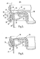
- Figures 5 and 6 illustrate one embodiment of fitment applied to a tin as illustrated in Figures 1 to 4.
- Figure 5 shows a cross-section of the upper part of the tin with the lid on and the fitment in a first position
- Figure 6 is a view similar to Figure 5 but with the fitment in a second or final position.
- the body 21 is formed in two parts comprising a lower or container part with a bottom (not shown) and side walls and an upper part shaped in Figure 5, to form the channel 27 and to provide an inwardly tapering outer annular lip 28.
- the fitment indicated generally by reference 29, has an annular inner rim member 30 seating on the top of the cap 33 and leaving substantially the whole of the centre part of the cap 33 uncovered and a plurality of grip tabs 31 projecting downwardly along the outside of the container 21 and each having a gripping projection or locking lug 32 at or near to its lower end to seat under the annular lip 28.
- the annular inner rim member 30 is of inverted V shape and is connected to an outer rim member 34 by , with spaces 42 inbetween, frangible connections 35kspanning a gap between the inner rim member 30 and the outer rim member 34. If desired a depending projection, not shown, may be provided to fit into the channel 27.
- the inner rim member 30 may be in the form of a complete disc-like cover for the lid.
- the fitment is provided with an annular tension belt 36 preferably shaped as shown and connected to an annular pillar 40 projecting upwardly from the outer rim member 34, by a number of frangible nibs or connections37.
- the outer rim member 34 and the grip tabs 31 meet at hinge point 38 and the outer rim member 34 and the grip tabs are shaped to provide a recess 39 to receive the belt 36.
- the pillar is shaped at 40 to form a lead ramp to assist the movement of the belt 36 from its first position (Fit 5) to its second position (Fig 6).
- frangible connections 35, frangible nibs 37 and grip tabs 31 may be provided and in one example we provide fifteen connections 35, thirty nibs 37 and fifteen tabs 31 each with a segmented locking lug 32.
- the belt 36 is telescoped downwardly into the position shown in Figure 6 thus breaking the nibs 37.
- the fitment is therefore applied to the closed tin by downward pressure until it assumes the position shown in Figure 6 and this movement may be facilitated by the use of a sprung piston means, indicated generally at 41, to hold the rim members steady.
- a sprung piston means indicated generally at 41
- a tear away band with a finger and thumb grip in the form of a depending tab may be provided as described hereinafter in connection with Figures 7, 8 and 9.
- the connections 35 may simply be broken, inner ring 30 with frangible connections 35 then being discarded having served their purposeand the lid 33 removed in the usual way.
- the outer ring and tension belt 36 remain captive on the rim of the tin for the life of the package.
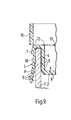
- a tear away band may be provided for example, as also described hereinafter in connection with Figures 7, 8 and 9 in which Figure 7 is a sectional side elevation showing a fitment, in the form of a closure including a tear ring, in accordance with the invention in position on a tube end before the tamper proof tear ring is snapped into position.
- Figure 8 is a view similar to Figure 7 with the tamper proof tear ring in its operative position
- Figure 9 is an enlarged detail showing the part marked X in Figure 7, the section being taken through a grip tab.
- a tube 1 of cardboard or the like has an open end 2 which is closed by means of a closure fitment 3 of plastic material such as polyprpylene or any other suitable material.
- the closure fitment has a plug part 4 which seats within the open end 2 of the tube 1 and which has a number of sealing rings 5 to make contact with the inside wall of the tube 1.
- the tube 1 is disposed vertically and the closure fitment 3 is applied to the top end of the tube 1 so that the wall of the plug part 4 is projecting downwards into the tube which is closed by the part 6.
- the top of the plug part 4 in Figures 7, 8 and 9 has an outwardly projecting rim 7 which seats upon the edge of the tube 1 and extends beyond the outer edge of the tube.
- rim 7 Depending from the rim 7 are a plurality of grip tabs 8.
- Each grip tab 8 has internal teeth 9 to serve , recess as gripping members and a pocketaor the like 10 on the outside.
- finger and thumb grip tab 11 projecting downwardly from the rim 7; the tab 11 is not provided with teeth.
- the rim is connected by frangible nibs 12 or other suitable frangible means to a tamper resistant ring 13, which, before application of the closure fitment 3 to a tube 1, projects upwardly from the rim 7, see Figures 7 and 9.
- the tamper resistant ring 13 has a tear tab 14 and upper and lower tear membranes 15 and 16 which run out respectively to the top and the bottom of the tamper resistant ring.
- the grips 8 can then be released manually from their gripping position and the closure fitment can be removed by lifting the tab 11. If necessary, the closure fitment can be replaced in position by pressing the plug part 4 into the open end of the tube and then manually pushing the grip tabs back into position although this latter action would not be necessary in normal domestic or office use.
- closure fitment or tamper resistant fitment is moulded or otherwise formed as one integral unit but it will be understood that if desired the closure or tamper resistant fitment may be formed in two parts of the same or different meterial. In such an embodiment the upper part of the closure or tamper resistant fitment may be made as a separate unit from the lower part. This is a less economical method of manufacture but is more versatile in design and choice of materials to be used.
Abstract
Description
- This invention is concerned with the provision of a tamper resistant fitment for a container.
- Many products are offered for sale in containers which comprise conventional container body and a conventional cap such as a simple push in cap. Examples of such conventional containers include paint tins and the traditional tins in which the well known product called Andrews Liver Salt is packed for saleo Hitherto such containers have not required any tamper resistant capability but recent events in USA have shown that in certain cases tamper resistance is desirable.
- In accordance with a feature of the present invention there is provided a tamper-resistant fitment for a container with a conventional cap characterised in that the fitment comprises an outer rim member adapted to seat on the top edge of the container, an inner member to seat on the top of the cap, a plurality of grip tabs projecting from the rim member so as to extend downwardly along the outside of the container gripping means on the grip tabs a tension belt to hold the grip tabs in operative position, and frangible means connecting the inner member to the outer member. In one embodiment when in operative position the fitment covers the outer marginal edge of the container top and at least a part of the cap and spans a gap that is provided between the outer marginal edge of the cap and the outer marginal edge of the container. This gap is provided to receive a tool to lever off the cap when it is desired to open the container. The inner member is preferably an inner rim member but in accordance with a further feature of the invention the inner member may cover the cap substantially completely instead of being just an inner rim member.. In accordance with another feature of the invention the tension belt may be in the form of a tamper-resistant tear ring connected to the outer rim member by frangible means. The arrangement of the tension belt may be such that the belt projects away from the container when the fitment is first applied to the container and the belt is then folded or telescoped downwards so that it embraces the grip tabs and forces the gripping means to engage with or press against the surface of the container with the gripping means engaged below an annular projection or lip on the container.
- The invention may also be used with advantage in connection with forms of container, other than containers with push in caps, for example, tubular containers such as tubes made of relatively soft material including cardboard, fibreboard and the like. The invention therefore also includes a fitment in the form of a closure comprising a plug part to seat within an end of the tube, an outwardly projecting rim to seat on the end of the tube, a plurality of grip tabs projecting from the rim to extend along the outside of the tube, gripping means on the inside of the grip tabs and a tension belt preferably in the form of a tamper-resistant tear ring connected to the rim by frangible means, the arrangement being such that the tamper-resistant ring projects away from the tube end when the fitment is first applied to the tube and that the ring is then telescoped, folded or snapped downwardly so that it embraces the grip tabs in the manner of a strap or belt and forces the gripping means to engage with the surface of the tube to prevent the closure being accidentally or otherwise removed until the tear ring is torn away.
- In order that the invention may be more clearly understood reference is now directed to the accompanying drawings given by way of example in which:-
- Figure 1 is a top plan view of a conventional tin with a simple push in cap eg a liver salts tin with the cap on,
- Figure 2 is a side view of the upper part of the tin illustrated in Figure 1,
- Figure 3 is a top plan view of the tin with the cap off, and Figure 4 is a side view of the cap.
- Referring first to Figures 1,2,3 and 4 it will be noted that the tin has a body indicated generally at 21 and a cap indicated generally at 22. The
cap 22 has acentre part 23 forming a shallow internal plug and an annularouter flange 24. Thebody 21 has an outer topmarginal edge 25, an inner topmarginal edge 26 and anannular channel 27 between theedges channel 27 and to lever the cap off after which the cap can be replaced giving virtually no indication that the cap has ever been removed. - One object of this invention is to provide a simple and effective fitment, removal of which will indicate that the cap may have been removed so that the contents of the tin may have been tampered with. Figures 5 and 6 illustrate one embodiment of fitment applied to a tin as illustrated in Figures 1 to 4. Figure 5 shows a cross-section of the upper part of the tin with the lid on and the fitment in a first position, and Figure 6 is a view similar to Figure 5 but with the fitment in a second or final position.
- Referring to Figures 5 and 6 it will be noted that the
body 21 is formed in two parts comprising a lower or container part with a bottom (not shown) and side walls and an upper part shaped in Figure 5, to form thechannel 27 and to provide an inwardly tapering outerannular lip 28. - The fitment, indicated generally by
reference 29, has an annularinner rim member 30 seating on the top of thecap 33 and leaving substantially the whole of the centre part of thecap 33 uncovered and a plurality ofgrip tabs 31 projecting downwardly along the outside of thecontainer 21 and each having a gripping projection orlocking lug 32 at or near to its lower end to seat under theannular lip 28. The annularinner rim member 30 is of inverted V shape and is connected to anouter rim member 34 by , withspaces 42 inbetween, frangible connections 35kspanning a gap between theinner rim member 30 and theouter rim member 34. If desired a depending projection, not shown, may be provided to fit into thechannel 27. Theinner rim member 30 may be in the form of a complete disc-like cover for the lid. - The fitment is provided with an
annular tension belt 36 preferably shaped as shown and connected to anannular pillar 40 projecting upwardly from theouter rim member 34, by a number of frangible nibs or connections37. Theouter rim member 34 and thegrip tabs 31 meet athinge point 38 and theouter rim member 34 and the grip tabs are shaped to provide arecess 39 to receive thebelt 36. The pillar is shaped at 40 to form a lead ramp to assist the movement of thebelt 36 from its first position (Fit 5) to its second position (Fig 6). Any desired and suitable number offrangible connections 35,frangible nibs 37 andgrip tabs 31 may be provided and in one example we provide fifteenconnections 35, thirtynibs 37 and fifteentabs 31 each with a segmentedlocking lug 32. To complete the application of thefitment 29 to thecontainer 21 thebelt 36 is telescoped downwardly into the position shown in Figure 6 thus breaking thenibs 37. The fitment is therefore applied to the closed tin by downward pressure until it assumes the position shown in Figure 6 and this movement may be facilitated by the use of a sprung piston means, indicated generally at 41, to hold the rim members steady. When in the position shown in Figure 6, it is almost impossible to remove the fitment or to open the tin by any other means without breaking thefrangible connections 35. To facilitate removal of the fitment a tear away band with a finger and thumb grip in the form of a depending tab may be provided as described hereinafter in connection with Figures 7, 8 and 9. Alternatively theconnections 35 may simply be broken,inner ring 30 withfrangible connections 35 then being discarded having served their purposeand thelid 33 removed in the usual way. The outer ring andtension belt 36 remain captive on the rim of the tin for the life of the package. In addition a tear away band may be provided for example, as also described hereinafter in connection with Figures 7, 8 and 9 in which Figure 7 is a sectional side elevation showing a fitment, in the form of a closure including a tear ring, in accordance with the invention in position on a tube end before the tamper proof tear ring is snapped into position. Figure 8 is a view similar to Figure 7 with the tamper proof tear ring in its operative position, and Figure 9 is an enlarged detail showing the part marked X in Figure 7, the section being taken through a grip tab. - In the drawings a
tube 1 of cardboard or the like has anopen end 2 which is closed by means of aclosure fitment 3 of plastic material such as polyprpylene or any other suitable material. The closure fitment has aplug part 4 which seats within theopen end 2 of thetube 1 and which has a number of sealing rings 5 to make contact with the inside wall of thetube 1. In Figure 7 thetube 1 is disposed vertically and theclosure fitment 3 is applied to the top end of thetube 1 so that the wall of theplug part 4 is projecting downwards into the tube which is closed by thepart 6. - The top of the
plug part 4 in Figures 7, 8 and 9 has an outwardly projectingrim 7 which seats upon the edge of thetube 1 and extends beyond the outer edge of the tube. Depending from therim 7 are a plurality ofgrip tabs 8. Eachgrip tab 8 hasinternal teeth 9 to serve , recess as gripping members and a pocketaor the like 10 on the outside. There is also one finger andthumb grip tab 11 projecting downwardly from therim 7; thetab 11 is not provided with teeth. The rim is connected byfrangible nibs 12 or other suitable frangible means to a tamperresistant ring 13, which, before application of theclosure fitment 3 to atube 1, projects upwardly from therim 7, see Figures 7 and 9. The tamperresistant ring 13 has atear tab 14 and upper andlower tear membranes - When the
closure fitment 3 is first applied to a tube the parts of the closure fitment are in the position shown in Figures 7 and 9 with thegrip tabs 8 only lightly touching the outer surface of the tube. The parts of the closure fitment are then moved into the position shown in Figure 8 by telescoping or folding over thering 13 and .snapping it into position in thepocket 10. When in this position, the pressure of the ring on the tabs causes theteeth 9 to bite into the outer surface of the tube so that theclosure 3 cannot accidentally fall out of the end of the tube and cannot be removed by manual manipulation without first tearing away thering 13. When it is desired to remove the closure fitment, a user grips thetab 14 and tears the ring away along thelines grips 8 can then be released manually from their gripping position and the closure fitment can be removed by lifting thetab 11. If necessary, the closure fitment can be replaced in position by pressing theplug part 4 into the open end of the tube and then manually pushing the grip tabs back into position although this latter action would not be necessary in normal domestic or office use. - We have therefore provided a closure fitment for a board or other tube in which the closure fitment is retained in position by grip tabs whcih are caused to engage with the outer surface of the tube by. an outer embracing tamper proof ring which is telescoped or folded over on to the grip tabs after the closure fitment has been applied to the tube, removal of the closure fitment then being impossible until the tamper proof ring is torn away.
- As described above and illustrated in 5, 7 and 9 the closure fitment or tamper resistant fitment is moulded or otherwise formed as one integral unit but it will be understood that if desired the closure or tamper resistant fitment may be formed in two parts of the same or different meterial. In such an embodiment the upper part of the closure or tamper resistant fitment may be made as a separate unit from the lower part. This is a less economical method of manufacture but is more versatile in design and choice of materials to be used.
- In the above description relating to Figures 7, 8 and 9 we have referred particularly to the use of the fitment as a closure for a container which in the form of a tube but it will be understood that without modification the fitment as described can be used as a closure fitment for a tubular container. On the other hand the fitment described in connection with Figures 5 and 6 cannot be used as a closure fitment without modification owing to the pressence of the
gaps 42. To modify the fitment of Figures 5 and 6 for use as a closure fitment thefrangible connections 35 andgaps 42 may be provided in an annular skirt projecting downwardly from the top of the fitment to which skirt the grip tabs may be connected. - In Figures 7, 8 and 9 the gripping means on the grip tabs bite into the surface of the tube and in Figures 5 and 6 the gripping means engage below the
lip 28. When the fitment is used with a tubular container of plastics or other material having a smooth and relatively hard surface the gripping means cannot bite into or engage with the container and in wuch cases other engaging means may be used such as adhesive pads on the tabs.
Claims (12)
Priority Applications (1)
| Application Number | Priority Date | Filing Date | Title |
|---|---|---|---|
| AT83303461T ATE32326T1 (en) | 1983-05-04 | 1983-06-15 | SAFETY ARRANGEMENT FOR A CONTAINER. |
Applications Claiming Priority (2)
| Application Number | Priority Date | Filing Date | Title |
|---|---|---|---|
| GB8312157 | 1983-05-04 | ||
| GB08312157A GB2120642B (en) | 1982-05-13 | 1983-05-04 | Tamper-resistant fitments and closures |
Publications (3)
| Publication Number | Publication Date |
|---|---|
| EP0124669A2 true EP0124669A2 (en) | 1984-11-14 |
| EP0124669A3 EP0124669A3 (en) | 1985-10-23 |
| EP0124669B1 EP0124669B1 (en) | 1988-02-03 |
Family
ID=10542116
Family Applications (1)
| Application Number | Title | Priority Date | Filing Date |
|---|---|---|---|
| EP83303461A Expired EP0124669B1 (en) | 1983-05-04 | 1983-06-15 | An improved tamper-resistant fitment for a container |
Country Status (7)
| Country | Link |
|---|---|
| US (1) | US4456143A (en) |
| EP (1) | EP0124669B1 (en) |
| JP (1) | JPS59209544A (en) |
| AT (1) | ATE32326T1 (en) |
| CA (1) | CA1240287A (en) |
| DE (1) | DE3375565D1 (en) |
| ZA (1) | ZA834851B (en) |
Families Citing this family (5)
| Publication number | Priority date | Publication date | Assignee | Title |
|---|---|---|---|---|
| US5303835A (en) * | 1992-06-24 | 1994-04-19 | Habley Medical Technology Corporation | Lyophilization cap and method |
| US5813554A (en) * | 1996-09-13 | 1998-09-29 | Diseno Industrial Mago, S.L. | Annular lock |
| EP0989065B1 (en) | 1996-11-25 | 2002-08-14 | Diseno Industrial Mago, S.L. | Sealed closure cap |
| US5938062A (en) * | 1997-10-01 | 1999-08-17 | Paramski; Walter P. | Food dispensing package |
| US8678212B2 (en) * | 2003-08-27 | 2014-03-25 | Sunrise Kitchen Co., Ltd. | Container and container cover for sealing the container opening |
Citations (2)
| Publication number | Priority date | Publication date | Assignee | Title |
|---|---|---|---|---|
| FR2197781A1 (en) * | 1972-09-01 | 1974-03-29 | Utilisation Ration Gaz | |
| US4087018A (en) * | 1976-04-09 | 1978-05-02 | Metal Box Limited | Tamper proof seal for a closure |
Family Cites Families (4)
| Publication number | Priority date | Publication date | Assignee | Title |
|---|---|---|---|---|
| DE2813940A1 (en) * | 1977-04-23 | 1978-10-26 | Zensho Honma | BOTTLE CAP |
| US4111330A (en) * | 1977-10-31 | 1978-09-05 | The Continental Group, Inc. | Reclosable vacuum container |
| IN149917B (en) * | 1978-04-10 | 1982-05-29 | Akerlund & Rausing Ab | |
| US4376493A (en) * | 1980-09-19 | 1983-03-15 | Sears, Roebuck And Co. | Lockable closure for containers |
-
1983
- 1983-06-15 EP EP83303461A patent/EP0124669B1/en not_active Expired
- 1983-06-15 AT AT83303461T patent/ATE32326T1/en not_active IP Right Cessation
- 1983-06-15 DE DE8383303461T patent/DE3375565D1/en not_active Expired
- 1983-07-04 ZA ZA834851A patent/ZA834851B/en unknown
- 1983-07-05 US US06/510,623 patent/US4456143A/en not_active Expired - Fee Related
- 1983-07-28 JP JP58136910A patent/JPS59209544A/en active Pending
-
1984
- 1984-02-06 CA CA000446848A patent/CA1240287A/en not_active Expired
Patent Citations (2)
| Publication number | Priority date | Publication date | Assignee | Title |
|---|---|---|---|---|
| FR2197781A1 (en) * | 1972-09-01 | 1974-03-29 | Utilisation Ration Gaz | |
| US4087018A (en) * | 1976-04-09 | 1978-05-02 | Metal Box Limited | Tamper proof seal for a closure |
Also Published As
| Publication number | Publication date |
|---|---|
| ZA834851B (en) | 1984-09-26 |
| CA1240287A (en) | 1988-08-09 |
| ATE32326T1 (en) | 1988-02-15 |
| JPS59209544A (en) | 1984-11-28 |
| DE3375565D1 (en) | 1988-03-10 |
| EP0124669A3 (en) | 1985-10-23 |
| EP0124669B1 (en) | 1988-02-03 |
| US4456143A (en) | 1984-06-26 |
Similar Documents
| Publication | Publication Date | Title |
|---|---|---|
| US4281774A (en) | Tamper proof snap cap | |
| US5129531A (en) | Closure assembly with breakaway tamper evident membrane | |
| CA1113887A (en) | Plastic cap and bottle neck | |
| US6206220B1 (en) | Vacuum container with reclosable sealing closure having a vaccuum release sealing button | |
| EP0244036B1 (en) | Pressure venting closure cap for a container spout | |
| US5758793A (en) | Reclosable top for can | |
| US4700860A (en) | Tamper indicating vacuum package | |
| US5975369A (en) | Resealable pushable container closure and cover therefor | |
| US5617968A (en) | Container cover having primary and secondary detent means | |
| US4027775A (en) | Tamper-indicating container and lid therefor | |
| US20030015542A1 (en) | Resealable closure for a container | |
| MXPA04008629A (en) | Plastic lid for a can. | |
| US4032029A (en) | Tamper-proof bottle cap and container | |
| US4522307A (en) | Child-resistant tamper-evident closure | |
| US3122261A (en) | Capseals for container closures | |
| US4456143A (en) | Tamper resistant fitment for a container | |
| JPH0440268B2 (en) | ||
| US4289252A (en) | Hermetically sealed container | |
| GB2120642A (en) | Tamper-resistance fitments and closures | |
| US2831600A (en) | Detachable closure | |
| JPH0130702B2 (en) | ||
| WO1979000722A1 (en) | Container with side wall,cover and tearing device produced as a unit | |
| JPH07237651A (en) | Bottle-sealing cover | |
| US2697532A (en) | Bottle cap | |
| GB2312207A (en) | Cap and plug closure assembly |
Legal Events
| Date | Code | Title | Description |
|---|---|---|---|
| PUAI | Public reference made under article 153(3) epc to a published international application that has entered the european phase |
Free format text: ORIGINAL CODE: 0009012 |
|
| AK | Designated contracting states |
Designated state(s): AT BE CH DE FR GB IT LI NL SE |
|
| PUAL | Search report despatched |
Free format text: ORIGINAL CODE: 0009013 |
|
| AK | Designated contracting states |
Designated state(s): AT BE CH DE FR GB IT LI NL SE |
|
| 17P | Request for examination filed |
Effective date: 19860304 |
|
| 17Q | First examination report despatched |
Effective date: 19861002 |
|
| GRAA | (expected) grant |
Free format text: ORIGINAL CODE: 0009210 |
|
| AK | Designated contracting states |
Kind code of ref document: B1 Designated state(s): AT BE CH DE FR GB IT LI NL SE |
|
| REF | Corresponds to: |
Ref document number: 32326 Country of ref document: AT Date of ref document: 19880215 Kind code of ref document: T |
|
| REF | Corresponds to: |
Ref document number: 3375565 Country of ref document: DE Date of ref document: 19880310 |
|
| ET | Fr: translation filed | ||
| ITF | It: translation for a ep patent filed |
Owner name: UFFICIO BREVETTI RICCARDI & C. |
|
| PLBE | No opposition filed within time limit |
Free format text: ORIGINAL CODE: 0009261 |
|
| STAA | Information on the status of an ep patent application or granted ep patent |
Free format text: STATUS: NO OPPOSITION FILED WITHIN TIME LIMIT |
|
| 26N | No opposition filed | ||
| PGFP | Annual fee paid to national office [announced via postgrant information from national office to epo] |
Ref country code: SE Payment date: 19890526 Year of fee payment: 7 |
|
| PGFP | Annual fee paid to national office [announced via postgrant information from national office to epo] |
Ref country code: FR Payment date: 19890531 Year of fee payment: 7 |
|
| PG25 | Lapsed in a contracting state [announced via postgrant information from national office to epo] |
Ref country code: GB Effective date: 19890615 |
|
| PGFP | Annual fee paid to national office [announced via postgrant information from national office to epo] |
Ref country code: CH Payment date: 19890616 Year of fee payment: 7 |
|
| PGFP | Annual fee paid to national office [announced via postgrant information from national office to epo] |
Ref country code: BE Payment date: 19890626 Year of fee payment: 7 |
|
| PGFP | Annual fee paid to national office [announced via postgrant information from national office to epo] |
Ref country code: AT Payment date: 19890627 Year of fee payment: 7 |
|
| ITTA | It: last paid annual fee | ||
| PGFP | Annual fee paid to national office [announced via postgrant information from national office to epo] |
Ref country code: NL Payment date: 19890630 Year of fee payment: 7 |
|
| PGFP | Annual fee paid to national office [announced via postgrant information from national office to epo] |
Ref country code: DE Payment date: 19890710 Year of fee payment: 7 |
|
| GBPC | Gb: european patent ceased through non-payment of renewal fee | ||
| PG25 | Lapsed in a contracting state [announced via postgrant information from national office to epo] |
Ref country code: AT Effective date: 19900615 |
|
| PG25 | Lapsed in a contracting state [announced via postgrant information from national office to epo] |
Ref country code: SE Effective date: 19900616 |
|
| PG25 | Lapsed in a contracting state [announced via postgrant information from national office to epo] |
Ref country code: LI Effective date: 19900630 Ref country code: CH Effective date: 19900630 Ref country code: BE Effective date: 19900630 |
|
| BERE | Be: lapsed |
Owner name: JOHNSEN & JORGENSEN (PLASTICS) LTD Effective date: 19900630 |
|
| PG25 | Lapsed in a contracting state [announced via postgrant information from national office to epo] |
Ref country code: NL Effective date: 19910101 |
|
| NLV4 | Nl: lapsed or anulled due to non-payment of the annual fee | ||
| PG25 | Lapsed in a contracting state [announced via postgrant information from national office to epo] |
Ref country code: FR Effective date: 19910228 |
|
| REG | Reference to a national code |
Ref country code: CH Ref legal event code: PL |
|
| PG25 | Lapsed in a contracting state [announced via postgrant information from national office to epo] |
Ref country code: DE Effective date: 19910301 |
|
| REG | Reference to a national code |
Ref country code: FR Ref legal event code: ST |
|
| EUG | Se: european patent has lapsed |
Ref document number: 83303461.4 Effective date: 19910206 |