EP0124333A2 - Apparatus for controlling polymerisation reactors - Google Patents
Apparatus for controlling polymerisation reactors Download PDFInfo
- Publication number
- EP0124333A2 EP0124333A2 EP84302743A EP84302743A EP0124333A2 EP 0124333 A2 EP0124333 A2 EP 0124333A2 EP 84302743 A EP84302743 A EP 84302743A EP 84302743 A EP84302743 A EP 84302743A EP 0124333 A2 EP0124333 A2 EP 0124333A2
- Authority
- EP
- European Patent Office
- Prior art keywords
- reactor
- flow
- temperature
- feed line
- olefin
- Prior art date
- Legal status (The legal status is an assumption and is not a legal conclusion. Google has not performed a legal analysis and makes no representation as to the accuracy of the status listed.)
- Granted
Links
Images


Classifications
-
- C—CHEMISTRY; METALLURGY
- C08—ORGANIC MACROMOLECULAR COMPOUNDS; THEIR PREPARATION OR CHEMICAL WORKING-UP; COMPOSITIONS BASED THEREON
- C08F—MACROMOLECULAR COMPOUNDS OBTAINED BY REACTIONS ONLY INVOLVING CARBON-TO-CARBON UNSATURATED BONDS
- C08F10/00—Homopolymers and copolymers of unsaturated aliphatic hydrocarbons having only one carbon-to-carbon double bond
-
- C—CHEMISTRY; METALLURGY
- C08—ORGANIC MACROMOLECULAR COMPOUNDS; THEIR PREPARATION OR CHEMICAL WORKING-UP; COMPOSITIONS BASED THEREON
- C08F—MACROMOLECULAR COMPOUNDS OBTAINED BY REACTIONS ONLY INVOLVING CARBON-TO-CARBON UNSATURATED BONDS
- C08F2/00—Processes of polymerisation
-
- B—PERFORMING OPERATIONS; TRANSPORTING
- B01—PHYSICAL OR CHEMICAL PROCESSES OR APPARATUS IN GENERAL
- B01J—CHEMICAL OR PHYSICAL PROCESSES, e.g. CATALYSIS OR COLLOID CHEMISTRY; THEIR RELEVANT APPARATUS
- B01J19/00—Chemical, physical or physico-chemical processes in general; Their relevant apparatus
- B01J19/0006—Controlling or regulating processes
- B01J19/002—Avoiding undesirable reactions or side-effects, e.g. avoiding explosions, or improving the yield by suppressing side-reactions
-
- B—PERFORMING OPERATIONS; TRANSPORTING
- B01—PHYSICAL OR CHEMICAL PROCESSES OR APPARATUS IN GENERAL
- B01J—CHEMICAL OR PHYSICAL PROCESSES, e.g. CATALYSIS OR COLLOID CHEMISTRY; THEIR RELEVANT APPARATUS
- B01J19/00—Chemical, physical or physico-chemical processes in general; Their relevant apparatus
- B01J19/0006—Controlling or regulating processes
- B01J19/0033—Optimalisation processes, i.e. processes with adaptive control systems
-
- B—PERFORMING OPERATIONS; TRANSPORTING
- B01—PHYSICAL OR CHEMICAL PROCESSES OR APPARATUS IN GENERAL
- B01J—CHEMICAL OR PHYSICAL PROCESSES, e.g. CATALYSIS OR COLLOID CHEMISTRY; THEIR RELEVANT APPARATUS
- B01J2219/00—Chemical, physical or physico-chemical processes in general; Their relevant apparatus
- B01J2219/00049—Controlling or regulating processes
- B01J2219/00051—Controlling the temperature
- B01J2219/00054—Controlling or regulating the heat exchange system
- B01J2219/00056—Controlling or regulating the heat exchange system involving measured parameters
- B01J2219/00058—Temperature measurement
-
- B—PERFORMING OPERATIONS; TRANSPORTING
- B01—PHYSICAL OR CHEMICAL PROCESSES OR APPARATUS IN GENERAL
- B01J—CHEMICAL OR PHYSICAL PROCESSES, e.g. CATALYSIS OR COLLOID CHEMISTRY; THEIR RELEVANT APPARATUS
- B01J2219/00—Chemical, physical or physico-chemical processes in general; Their relevant apparatus
- B01J2219/00049—Controlling or regulating processes
- B01J2219/00051—Controlling the temperature
- B01J2219/00054—Controlling or regulating the heat exchange system
- B01J2219/00056—Controlling or regulating the heat exchange system involving measured parameters
- B01J2219/00069—Flow rate measurement
-
- B—PERFORMING OPERATIONS; TRANSPORTING
- B01—PHYSICAL OR CHEMICAL PROCESSES OR APPARATUS IN GENERAL
- B01J—CHEMICAL OR PHYSICAL PROCESSES, e.g. CATALYSIS OR COLLOID CHEMISTRY; THEIR RELEVANT APPARATUS
- B01J2219/00—Chemical, physical or physico-chemical processes in general; Their relevant apparatus
- B01J2219/00049—Controlling or regulating processes
- B01J2219/00051—Controlling the temperature
- B01J2219/00054—Controlling or regulating the heat exchange system
- B01J2219/00072—Mathematical modelling
-
- B—PERFORMING OPERATIONS; TRANSPORTING
- B01—PHYSICAL OR CHEMICAL PROCESSES OR APPARATUS IN GENERAL
- B01J—CHEMICAL OR PHYSICAL PROCESSES, e.g. CATALYSIS OR COLLOID CHEMISTRY; THEIR RELEVANT APPARATUS
- B01J2219/00—Chemical, physical or physico-chemical processes in general; Their relevant apparatus
- B01J2219/00049—Controlling or regulating processes
- B01J2219/00164—Controlling or regulating processes controlling the flow
-
- B—PERFORMING OPERATIONS; TRANSPORTING
- B01—PHYSICAL OR CHEMICAL PROCESSES OR APPARATUS IN GENERAL
- B01J—CHEMICAL OR PHYSICAL PROCESSES, e.g. CATALYSIS OR COLLOID CHEMISTRY; THEIR RELEVANT APPARATUS
- B01J2219/00—Chemical, physical or physico-chemical processes in general; Their relevant apparatus
- B01J2219/00049—Controlling or regulating processes
- B01J2219/00243—Mathematical modelling
-
- B—PERFORMING OPERATIONS; TRANSPORTING
- B01—PHYSICAL OR CHEMICAL PROCESSES OR APPARATUS IN GENERAL
- B01J—CHEMICAL OR PHYSICAL PROCESSES, e.g. CATALYSIS OR COLLOID CHEMISTRY; THEIR RELEVANT APPARATUS
- B01J2219/00—Chemical, physical or physico-chemical processes in general; Their relevant apparatus
- B01J2219/00049—Controlling or regulating processes
- B01J2219/00245—Avoiding undesirable reactions or side-effects
- B01J2219/00259—Preventing runaway of the chemical reaction
- B01J2219/00261—Predicting runaway of the chemical reaction
-
- C—CHEMISTRY; METALLURGY
- C08—ORGANIC MACROMOLECULAR COMPOUNDS; THEIR PREPARATION OR CHEMICAL WORKING-UP; COMPOSITIONS BASED THEREON
- C08F—MACROMOLECULAR COMPOUNDS OBTAINED BY REACTIONS ONLY INVOLVING CARBON-TO-CARBON UNSATURATED BONDS
- C08F2400/00—Characteristics for processes of polymerization
- C08F2400/02—Control or adjustment of polymerization parameters
Definitions
- This invention relates to apparatus for controlling polymerisation reactors.
- Low density polyethylene is an important basic polymer in a consumer oriented society. Over the years, its manufacturing processes have changed from the use of continuous stirred tank reactors to the use of tubular reactors for polymerisation, in large part due to process economics. In the tubular reactor, heat removal is accomplished by externally cooling the reactor tube.
- tubular reactors for ethylene polymerisation instead of autoclave type reactors, is disclosed in Polyolefin Production Processes -Latest Developments, M.P. Sittig, Noyes Data Corp., Park Ridge, N.J., U.S.A., 1976.
- Most low density polyethylene is made at high pressures ranging from 1,000 to 3,350 atm. pressure using a free radical initiator/catalyst such as peroxides, nitrogen compounds and metallic catalysts.
- the basic steps in the process are the initial compression of purified ethylene to the reactor pressures, introduction of free radical initiator/catalyst at some stage of compression, polymerisation and removal of exothermic heat of reaction, reaction mixture let down, product separation and finishing.
- a tubular reactor for accomplishing at least some of these steps is disclosed in US Patent No. US-A-4 008 049 (Clemmer et al).
- ethylene feed to the reactor be 99.9% pure and acetylene free. Commonly acceptable limits for acetylene are less than loppm. Ethylene gas feed should also contain less than 440ppm oxygen since higher oxygen content results in lower reaction rate and thus lower polymer yield.
- the initiator/catalyst are free radicals and predominantly oxides and peroxides. From 0.01 to 10% by weight may be added, based upon desired polymer weight. Liquid catalyst is injected at multiple points in connecting lines between one or more compressers and the reactor, at a temperature higher than the polymer melting point.
- Temperatures of 180 to 200°C are commonly used in high pressure polymerisation. Actual operating temperature depends on the temperature required for thermal decomposition of catalyst to provide free radicals for initiation of polymerisation.
- This reactor operating temperature is well above the critical temperature of ethylene. High operating pressures are therefore required to force the ethylene molecules together and ensure that free radicals will collide with an ethyl molecule during their short lifetime. The above- mentioned operating pressure range is therefore used in the low density polyethylene process.
- a further problem is that the amount of catalyst added is based on feed flow rate to the reactor. This is fixed for the operation since it is considered independent of feed flow rate as the catalyst control system does not account for variations in the feed flow rate.
- a still further problem of the prior art is that significant amounts of operator attention are required during the process. This is because an operator must not only observe the process behaviour but must also adjust set points for temperature and catalyst, based on his knowledge of the process and a relationship of product quality vs. reactor temperature and catalyst flow rate vs. feed flow rate.
- apparatus for controlling a polymerisation reactor having a feed line for a raw material to be polymerised, cooling means for cooling the reactor using a flow of coolant, and an exit line for a product of polymerisation in the reactor, the apparatus being characterised by:
- the control of the coolant flow in accordance with the coolant flow value can enable the reduction of fluctuations in product quality as well as deposits of polymer on walls of the reactor due to excessive cooling.
- the present invention may be so embodied as to provide a system or apparatus and a method for controlling and optimising a polymerisation reactor, particularly a tube reactor for polyolefin, and more particularly polyethylene production.
- a polymerisation reactor particularly a tube reactor for polyolefin, and more particularly polyethylene production.
- Preferred such systems and methods described hereinbelow are applicable to controlling a low density polyethylene reaction in a tubular reactor so that product quality is maintained, temperature control is utilised to avoid the occurrence of conditions which may damage the equipment, and a desired production rate is achieved.
- the apparatus is preferably so constructed that a desired production rate set point can be set manually and utilised in a production controller which compares the set point to actual production as determined by raw material concentration in the exit line of the reactor, to control all material feed flow to the reactor whereby variations in raw material polymerisation rate is considered to avoid fluctuations in the actual production rate.
- the apparatus preferably comprises catalyst supply means for supplying catalyst to various points in the feed line of the reactor, control being effected on the basis of total feed flow to the reactor.
- the invention is preferably so implemented as to maximise polymerisation, in particular to maximise ethylene conversion in the manufacturing process for low density polyethylene, by optimising certain process parameters such as catalyst flow rate, reactor temperature, coolant flow rate and reactor exit temperature.
- Preferred apparatus embodying the invention for controlling and optimising a polymerisation reactor is simple in design, rugged in construction and economical to manufacture.
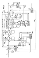
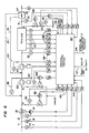
- Figure 1 shows a control apparatus or arrangement for a tubular reactor 10 having a feed line 4 for a raw material which in this case is ethylene.
- the tubular reactor 10 is for the low density polymerisation of ethylene into polyethylene.
- An exit line 8 from the reactor 10 supplies a mixture of ethylene and its polymer to a product separator or separator unit 24.
- a primary compressor 52 compresses the ethylene gas and the gas is further compressed by a high pressure compressor 54 before it is supplied to the reactor 10.
- a low pressure recycling arrangement or circuit generally designated 58 receives low pressure recycled ethylene gas from the product separator 24 over a line 23 and supplies it to the feed line 4 upstream of the primary compressor 52.
- high pressure recycled gas is provided over a line 25 to a high pressure recycling arrangement or circuit generally designated 60 and supplied to a point in the feed line 4 upstream of the high pressure compressor 54.
- Complete control of the tubular reactor 10 is achieved using a product quality control unit 20, a temperature control unit 26, a production rate control unit 46, a catalyst control unit 50 and a pressure control unit 77.
- Product quality is controlled by manipulating reactor temperature. Moreover, a temperature control is essential for controlling ethylene conversion, removing heat of reaction, and avoiding reactor tube plugging due to polymer deposits.
- the quality control unit 20 receives a product quality set point over a line 47 and compares it with an actual product quality sensed by a product quality sensor 22 at a point downstream of the product separator 24.
- An output of the product quality control unit 20 corresponds to a desired reactor temperature and is applied to the temperature control unit 26 over a line 28.
- the desired reactor temperature functions as a set point for the temperature control unit 26, which receives an actual temperature value from a maximum temperature unit 34.
- the temperature control unit 26 may also utilise a representative reactor temperature value to generate a desired flow rate value for coolant to be supplied by a coolant flow valve 40 controlled by a flow controller 38 connected to the temperature control unit 26.
- the desired flow rate value is applied over a line 36 with coolant flow information being provided by a flow transmitter 42 back to the flow controller 38.
- the maximum or representative reactor temperature is provided by a plurality of temperature sensors 30 for sensing temperatures along the length of the reactor 10, and an input temperature sensor 32.
- the control scheme carried out by the apparatus of Figure 1 reduces fluctuations in product quality since it is the primary control variable and the temperature set point is determined for a desired product quality. Also, the desired coolant flow rate is determined by the temperature control unit 26 so that excessive cooling is avoided. This in turn reduces polymer deposits in the reactor tube which result from excessive cooling.
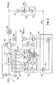
- Figure 2 shows in greater detail a preferred form of cascade control system for temperature quality control that can be used in the apparatus of Figure 1.
- the desired product quality is compared with the actual product quality in the product quality control unit 20.
- a suitable delay between the reactor 10 and the point of quality measurement is applied by a delay element 70.
- a similar delay feature is provided in the temperature control unit 26, which includes a temperature controller 72.
- the maximum temperature unit 34 provides both maximum and minimum temperature values for the reactor 10, which values can be provided over lines 74 for alarm, display and emergency control functions. The maximum temperature value is also provided to the temperature control unit 26.
- Figure 2 also illustrates the pressure control unit 77, which facilitates discharge of a polymer-ethylene mixture from the reactor 10 via a let down valve arrangement comprising valves 76, 80, 82.
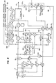
- Catalyst and production rate control elements of the apparatus of Figure 1 are shown in Figure 3.
- a desired production rate set point is manually entered in the production rate control unit 46 and an actual production rate is determined from ethylene concentration sensed by a concentration transmitter 44.
- the total feed flow rate for ethylene is also provided to the production control unit 46.
- a summation of flows in the high and low recycling arrangements or circuits 58, 60, as well as the feed flow from a flow transmitter 12, is taken in a summation unit 62 and applied to the production rate control unit 46.
- An output on a line 48 of the production rate control unit 46 acts as a set point for a fresh ethylene flow controller 14 which controls a valve 16 in the feed line 4.
- the production rate control unit 46 includes a flow controller 49 which receives the desired product rate set point over the line 47.
- Catalyst flow from a catalyst supply line 56 is controlled by the catalyst control unit 50 which supplies catalyst to a plurality of points (labelled A and B) on the feed line 4.
- the amount of catalyst added to the reactor feed stream is a function of the quantity of ethylene entering the reactor.
- the total flow rate is again provided by the summation unit 62. This provides a set point for a total catalyst flow controller 64, which receives inputs from catalyst flow transmitters 84, 86. An output signal from the controller 64 is proportioned for catalyst flow to the points A and B over controllers 66 and 68, respectively.
- the apparatus or system in general can be simplified by eliminating sensors whose values are constant due to up/downstream control.
- the ethylene flow pressure is normally held constant, so that a pressure transmitter 9 can be eliminated as it is shown in Figure 3.
- a temperature transmitter 11 and an ethylene concentration transmitter 7 are also provided to modify the flow value from the flow transmitter 12 to provide an accurate value for ethylene flow for the summation unit 62. Similar substances are utilised in the recycling arrangements 58 and 60.
- Advantages of the above-described integrated control apparatus or system for a tubular reactor in the manufacture of low density polyethylene includes the requirement of only two set points, one for quality and one for production rate. Consequently, a reduction in operator attention is permitted.
- a close control of product quality as a function of reactor temperature is also provided, as well as the maintanence of catalyst addition at a desired level.
- Close temperature control also reduces the occurrence of conditions which may damage the reactor equipment.
- the apparatus may be implemented using Bailey 7000 Electronic Analog Instrumentation.
- a microprocessor based on the Network 90 control computer can also be used for control, alarm, calculation and operation interface.
- Network 90 is a trademark of the Bailey Meter Co.
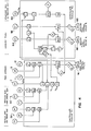
- Figures 4 and 5 illustrate the use of a Network 90 control module (product specification E 93-906) for implementing apparatus embodying the invention.
- Operator interface may be provided by Digital Control Stations (product specification E93-902), which are dedicated panel-board devices, or by a CRT based Operator Interface Unit (product specification E93-901).
- FIGs 6 and 7, where corresponding numerals signify the same or similar parts as in Figures 1 to 3, show an optimising control apparatus embodying the invention for ethylene conversion.
- control systems are based on a fixed ethylene conversion per pass through the reactor, due to the importance of heat removal.
- the amount of conversation per pass is actually lower than the recommended value for plant operation and significantly lower than plant design values. This is due to the fact that operating personnel wish to maintain reactor operations well within safe limits, which is well justified.
- Lower conversion per pass results in increased plant operating cost due to recompression of recycled gases from low and high pressure separators, and interstage cooling during compression.
- the embodiment of the invention as shown in Figures 6 and 7 provides an optimising control which maximises conversion per pass within the constraints placed by reactor cooling, production rate, polymerisation reaction, and the like.
- the total amount of catalyst to be added to the reactor feed stream is a function of feed flow rate, maximum reactor temperature and desired product quality. Functionally, this relationship is expressed by: where:
- Equation (1) can be obtained either by regression analysis of plant operating data and catalyst data provided by its manufacturer for a specific catalyst.
- Equation (6) can be obtained from state of the art knowledge as found for example, in Theory of Free Radical Polymerization, K.S. Bagdasar'yan, 1968 and Chemical Engineering Kinetics, J.M. Smith, McGraw Hill, 1970.
- the quality of the low density polyethylene is a function of maximum reactor temperature and catalyst addition to the reactor feed stream. For a given feed flow rate, this relationship is functionally given as:
- Equation (12) can be determined by regression analysis of operating data.
- Low density polyethylene production rate is dependent on total feed flow rate, ethylene concentration in the reactor's feed stream and conversion per pass in the reactor. This relationship is functionally expressed as:
- the problem to be overcome in optimising the reactor control is to maximise with respect to T m ,F c ,F q and T 2 such that the following limitations are satisfied:
- the control apparatus utilises a control computer 90 which receives inputs from the various sensors of the apparatus through analog to digital (A/D) converters 88. Control outputs from the control computer 90 to the plant are interfaced through digital to analog (D/A) converters 89.
- A/D analog to digital
- D/A digital to analog
- Signals for alarm, display and emergency control are provided over a line 94.
- the outputs from the blocks 92 and 93 are provided to a block 96 for obtaining a continuous running average of the processed data. Signals are sampled at intervals of AT minutes.
- the outputs of blocks 92, 93 and 96 are also provided to a limit checking block 97 for detecting an alarm condition and providing an alarm and emergency control signal over the line 94.
- An optimisation program for an optimised process model is provided from a process model 99.
- the process model 99 is established according to the foregoing process analysis.
- the optimisation program is executed every AT minutes, which is greater than or equal to five minutes and less than or equal to 15 minutes. This execution period is established using the continuous running average data of the block 96 and the desired quantities for the various parameters obtained in an optimisation block 98.
- the optimisation block 98 thus establishes a desired catalyst flow rate F , desired temperature T , maximum conversion x , desired c m P ⁇ maximum coolant flow rate F and desired reactor exit temperature T 2 .
- the maximum temperature T is outputted as a control signal for the temperature control unit 26, acting as a set point.
- the temperature control unit 26 generates the desired coolant flow rate set point for the flow controller 38, which manipulates the coolant flow rate to the reactor 10 as noted above.
- the desired coolant flow F q can be directly outputted to the coolant flow rate controller (not shown), thus eliminating the temperature control unit 26.
- the maximum conversion signal x p is provided through a feed flow block 91 where the desired feed flow rate for the specified product rate is determined by expression (15) above and outputted to the feed (fresh ethylene) flow controller 14.
- the maximum catalyst flow signal F c is provided over a block 95 to control catalyst flow to the individual points A and B in the feed stream. Catalyst flow at each point of addition is determined by equation (2) above and values for P. are manually entered.
- the output of the block 95 is provided to the catalyst flow controllers 66 and 68.
- an oxygen concentration transmitter 18 is provided since this variable affects ethylene conversion, as shown in equation (6) above, as well.
Landscapes
- Chemical & Material Sciences (AREA)
- Chemical Kinetics & Catalysis (AREA)
- Organic Chemistry (AREA)
- Health & Medical Sciences (AREA)
- Medicinal Chemistry (AREA)
- Polymers & Plastics (AREA)
- Engineering & Computer Science (AREA)
- Automation & Control Theory (AREA)
- Polymerisation Methods In General (AREA)
- Addition Polymer Or Copolymer, Post-Treatments, Or Chemical Modifications (AREA)
- Other Resins Obtained By Reactions Not Involving Carbon-To-Carbon Unsaturated Bonds (AREA)
- Polyesters Or Polycarbonates (AREA)
Abstract
Description
- This invention relates to apparatus for controlling polymerisation reactors.
- Low density polyethylene is an important basic polymer in a consumer oriented society. Over the years, its manufacturing processes have changed from the use of continuous stirred tank reactors to the use of tubular reactors for polymerisation, in large part due to process economics. In the tubular reactor, heat removal is accomplished by externally cooling the reactor tube.
- The use of tubular reactors for ethylene polymerisation, instead of autoclave type reactors, is disclosed in Polyolefin Production Processes -Latest Developments, M.P. Sittig, Noyes Data Corp., Park Ridge, N.J., U.S.A., 1976.
- Most low density polyethylene is made at high pressures ranging from 1,000 to 3,350 atm. pressure using a free radical initiator/catalyst such as peroxides, nitrogen compounds and metallic catalysts. The basic steps in the process are the initial compression of purified ethylene to the reactor pressures, introduction of free radical initiator/catalyst at some stage of compression, polymerisation and removal of exothermic heat of reaction, reaction mixture let down, product separation and finishing. A tubular reactor for accomplishing at least some of these steps is disclosed in US Patent No. US-A-4 008 049 (Clemmer et al).
- Since ethylene polymerisation is an exothermic process, exothermic heat must be removed. Such heat removal has been achieved by externally cooling the reactor tube, and feeding a portion of cool ethylene feed as a starting material to a high temperature reactor zone.
- It is also important that ethylene feed to the reactor be 99.9% pure and acetylene free. Commonly acceptable limits for acetylene are less than loppm. Ethylene gas feed should also contain less than 440ppm oxygen since higher oxygen content results in lower reaction rate and thus lower polymer yield.
- The initiator/catalyst, as noted above, are free radicals and predominantly oxides and peroxides. From 0.01 to 10% by weight may be added, based upon desired polymer weight. Liquid catalyst is injected at multiple points in connecting lines between one or more compressers and the reactor, at a temperature higher than the polymer melting point.
- Temperatures of 180 to 200°C are commonly used in high pressure polymerisation. Actual operating temperature depends on the temperature required for thermal decomposition of catalyst to provide free radicals for initiation of polymerisation.
- This reactor operating temperature is well above the critical temperature of ethylene. High operating pressures are therefore required to force the ethylene molecules together and ensure that free radicals will collide with an ethyl molecule during their short lifetime. The above- mentioned operating pressure range is therefore used in the low density polyethylene process.
- Major problems exist in known ethylene polymerisation processes using tubular reactors.
- One of these problems is that product quality is achieved by maintaining reactor temperature at a pre-specified level. That is, there is no direct product quality control. This approach results in significant fluctuations in product quality due to variations in reactor temperature caused by discharging reactor products through let down valves. A polymer-ethylene mixture is discharged from the reactor tube by opening and closing such a let down valve to lower reactor pressure intermittently. This causes pressure fluctuations of 19.61 to 98.10 MPa (200 to 1,000 kgf/cm2).
- Another problem is that the application of excessive cooling lowers reactor cooling zone temperature and results in polymer deposits on the tube wall. Pressure drops appear as a consequence and, in a worst case, the reactor tube may become clogged. This may result in damage to the equipment.
- A further problem is that the amount of catalyst added is based on feed flow rate to the reactor. This is fixed for the operation since it is considered independent of feed flow rate as the catalyst control system does not account for variations in the feed flow rate.
- A still further problem of the prior art is that significant amounts of operator attention are required during the process. This is because an operator must not only observe the process behaviour but must also adjust set points for temperature and catalyst, based on his knowledge of the process and a relationship of product quality vs. reactor temperature and catalyst flow rate vs. feed flow rate.
- According to the invention there is provided apparatus for controlling a polymerisation reactor having a feed line for a raw material to be polymerised, cooling means for cooling the reactor using a flow of coolant, and an exit line for a product of polymerisation in the reactor, the apparatus being characterised by:
- a quality sensor for sensing the actual quality of the product in the exit line;
- quality control means connected to the quality sensor for receiving a desired product quality set point and comparing it with the actual quality of the product to generate a desired temperature value of the reactor;
- temperature sensing means associated with the reactor for sensing a representative temperature thereof; and
- temperature control means connected to the temperature sensing means and the quality control means for comparing the representative temperature of the reactor with the desired temperature value therefor to generate a coolant flow value, the temperature control means being connected to the cooling means for controlling the coolant flow to the reactor in accordance with the coolant flow value.
- The control of the coolant flow in accordance with the coolant flow value can enable the reduction of fluctuations in product quality as well as deposits of polymer on walls of the reactor due to excessive cooling.
- The present invention may be so embodied as to provide a system or apparatus and a method for controlling and optimising a polymerisation reactor, particularly a tube reactor for polyolefin, and more particularly polyethylene production. Preferred such systems and methods described hereinbelow are applicable to controlling a low density polyethylene reaction in a tubular reactor so that product quality is maintained, temperature control is utilised to avoid the occurrence of conditions which may damage the equipment, and a desired production rate is achieved.
- The apparatus is preferably so constructed that a desired production rate set point can be set manually and utilised in a production controller which compares the set point to actual production as determined by raw material concentration in the exit line of the reactor, to control all material feed flow to the reactor whereby variations in raw material polymerisation rate is considered to avoid fluctuations in the actual production rate.
- The apparatus preferably comprises catalyst supply means for supplying catalyst to various points in the feed line of the reactor, control being effected on the basis of total feed flow to the reactor.
- The invention is preferably so implemented as to maximise polymerisation, in particular to maximise ethylene conversion in the manufacturing process for low density polyethylene, by optimising certain process parameters such as catalyst flow rate, reactor temperature, coolant flow rate and reactor exit temperature.
- Preferred apparatus embodying the invention for controlling and optimising a polymerisation reactor is simple in design, rugged in construction and economical to manufacture.
- The invention will now be further described, by way of illustrative and non-limiting example, with reference to the accompanying drawings, in which:
- Figure 1 is a block diagram of apparatus embodying the invention for controlling a low density polyethylene reactor;
- Figure 2 is a block diagram of portions of the apparatus of Figure 1 for product quality control and pressure control;
- Figure 3 is a block diagram of portions of the apparatus of Figure 1 for controlling the addition of catalyst to the reactor and the production rate of the reactor;
- Figure 4 is a block diagram showing elements for implementing logic for catalyst addition and production rate control in apparatus embodying the invention;
- Figure 5 is a block diagram showing elements for implementing logic for product quality control in apparatus embodying the invention;
- Figure 6 is a block diagram showing an ethylene polymerisation reactor with control apparatus in accordance with a further embodiment of the invention; and
- Figure 7 is a block diagram showing elements of a control computer system used in the embodiment of Figure 6.
- Referring to the drawings, Figure 1 shows a control apparatus or arrangement for a
tubular reactor 10 having afeed line 4 for a raw material which in this case is ethylene. Thetubular reactor 10 is for the low density polymerisation of ethylene into polyethylene. - An
exit line 8 from thereactor 10 supplies a mixture of ethylene and its polymer to a product separator orseparator unit 24. In known fashion, aprimary compressor 52 compresses the ethylene gas and the gas is further compressed by ahigh pressure compressor 54 before it is supplied to thereactor 10. - A low pressure recycling arrangement or circuit generally designated 58 receives low pressure recycled ethylene gas from the
product separator 24 over aline 23 and supplies it to thefeed line 4 upstream of theprimary compressor 52. In a similar fashion, high pressure recycled gas is provided over aline 25 to a high pressure recycling arrangement or circuit generally designated 60 and supplied to a point in thefeed line 4 upstream of thehigh pressure compressor 54. - Complete control of the
tubular reactor 10 is achieved using a productquality control unit 20, atemperature control unit 26, a productionrate control unit 46, acatalyst control unit 50 and apressure control unit 77. - Product quality is controlled by manipulating reactor temperature. Moreover, a temperature control is essential for controlling ethylene conversion, removing heat of reaction, and avoiding reactor tube plugging due to polymer deposits.
- As shown in Figure 1, the
quality control unit 20 receives a product quality set point over aline 47 and compares it with an actual product quality sensed by aproduct quality sensor 22 at a point downstream of theproduct separator 24. An output of the productquality control unit 20 corresponds to a desired reactor temperature and is applied to thetemperature control unit 26 over aline 28. The desired reactor temperature functions as a set point for thetemperature control unit 26, which receives an actual temperature value from amaximum temperature unit 34. Thetemperature control unit 26 may also utilise a representative reactor temperature value to generate a desired flow rate value for coolant to be supplied by acoolant flow valve 40 controlled by aflow controller 38 connected to thetemperature control unit 26. The desired flow rate value is applied over aline 36 with coolant flow information being provided by aflow transmitter 42 back to theflow controller 38. - The maximum or representative reactor temperature is provided by a plurality of
temperature sensors 30 for sensing temperatures along the length of thereactor 10, and aninput temperature sensor 32. - The control scheme carried out by the apparatus of Figure 1 reduces fluctuations in product quality since it is the primary control variable and the temperature set point is determined for a desired product quality. Also, the desired coolant flow rate is determined by the
temperature control unit 26 so that excessive cooling is avoided. This in turn reduces polymer deposits in the reactor tube which result from excessive cooling. - Figure 2 shows in greater detail a preferred form of cascade control system for temperature quality control that can be used in the apparatus of Figure 1.
- The desired product quality is compared with the actual product quality in the product
quality control unit 20. A suitable delay between thereactor 10 and the point of quality measurement is applied by adelay element 70. A similar delay feature is provided in thetemperature control unit 26, which includes atemperature controller 72. - The
maximum temperature unit 34 provides both maximum and minimum temperature values for thereactor 10, which values can be provided overlines 74 for alarm, display and emergency control functions. The maximum temperature value is also provided to thetemperature control unit 26. - Figure 2 also illustrates the
pressure control unit 77, which facilitates discharge of a polymer-ethylene mixture from thereactor 10 via a let down valvearrangement comprising valves - Catalyst and production rate control elements of the apparatus of Figure 1 are shown in Figure 3. A desired production rate set point is manually entered in the production
rate control unit 46 and an actual production rate is determined from ethylene concentration sensed by aconcentration transmitter 44. The total feed flow rate for ethylene is also provided to theproduction control unit 46. For this purpose, a summation of flows in the high and low recycling arrangements orcircuits flow transmitter 12, is taken in asummation unit 62 and applied to the productionrate control unit 46. - An output on a
line 48 of the productionrate control unit 46 acts as a set point for a freshethylene flow controller 14 which controls avalve 16 in thefeed line 4. - In this way, variations in ethylene polymerisation rate are taken into account and the actual production rate does not fluctuate significantly. The production
rate control unit 46 includes aflow controller 49 which receives the desired product rate set point over theline 47. - Catalyst flow from a
catalyst supply line 56 is controlled by thecatalyst control unit 50 which supplies catalyst to a plurality of points (labelled A and B) on thefeed line 4. The amount of catalyst added to the reactor feed stream is a function of the quantity of ethylene entering the reactor. The total flow rate is again provided by thesummation unit 62. This provides a set point for a totalcatalyst flow controller 64, which receives inputs fromcatalyst flow transmitters controller 64 is proportioned for catalyst flow to the points A and B overcontrollers - The apparatus or system in general can be simplified by eliminating sensors whose values are constant due to up/downstream control. For example, the ethylene flow pressure is normally held constant, so that a
pressure transmitter 9 can be eliminated as it is shown in Figure 3. Atemperature transmitter 11 and anethylene concentration transmitter 7 are also provided to modify the flow value from theflow transmitter 12 to provide an accurate value for ethylene flow for thesummation unit 62. Similar substances are utilised in therecycling arrangements - Advantages of the above-described integrated control apparatus or system for a tubular reactor in the manufacture of low density polyethylene, in particular, includes the requirement of only two set points, one for quality and one for production rate. Consequently, a reduction in operator attention is permitted.
- A close control of product quality as a function of reactor temperature is also provided, as well as the maintanence of catalyst addition at a desired level.
- Close temperature control also reduces the occurrence of conditions which may damage the reactor equipment.
- The apparatus may be implemented using Bailey 7000 Electronic Analog Instrumentation. A microprocessor based on the
Network 90 control computer can also be used for control, alarm, calculation and operation interface.Network 90 is a trademark of the Bailey Meter Co. - Figures 4 and 5 illustrate the use of a
Network 90 control module (product specification E 93-906) for implementing apparatus embodying the invention. Operator interface may be provided by Digital Control Stations (product specification E93-902), which are dedicated panel-board devices, or by a CRT based Operator Interface Unit (product specification E93-901). - The elements in Figures 4 and 5 are labelled with numerals corresponding to those in Figures 1 to 3, and with symbols to indicate functions to be achieved by each element.
- Figures 6 and 7, where corresponding numerals signify the same or similar parts as in Figures 1 to 3, show an optimising control apparatus embodying the invention for ethylene conversion.
- In general, control systems are based on a fixed ethylene conversion per pass through the reactor, due to the importance of heat removal. The amount of conversation per pass is actually lower than the recommended value for plant operation and significantly lower than plant design values. This is due to the fact that operating personnel wish to maintain reactor operations well within safe limits, which is well justified. Lower conversion per pass however, results in increased plant operating cost due to recompression of recycled gases from low and high pressure separators, and interstage cooling during compression.
- The embodiment of the invention as shown in Figures 6 and 7 provides an optimising control which maximises conversion per pass within the constraints placed by reactor cooling, production rate, polymerisation reaction, and the like.
- To better understand the apparatus, the following process analysis should be considered.
- The total amount of catalyst to be added to the reactor feed stream is a function of feed flow rate, maximum reactor temperature and desired product quality. Functionally, this relationship is expressed by:

- F = total catalyst flow rate (kg/h);
- Ff = total ethylene flow rate (kg/h); Tm = maximum reactor temperature (K); and
- QR = desired product quality.
- Equation (1) can be obtained either by regression analysis of plant operating data and catalyst data provided by its manufacturer for a specific catalyst.
- It should be noted that operating pressure does not affect catalyst flow since reactor pressure is fixed and constant due to compressor operation. Contributions to pressure fluctuations have therefore been omitted.
- As catalyst is added at several points in the feed stream (the points A and B in Figure 6), the flow at each point being given by:

- Fci = catalyst flow at a point i (kg/h); and
- Pi = fraction of total flow added at the point i (a constant).
- The constraint on total catalyst flow is established by a maximum and minimum flow allowed, as follows:

- In the
reactor 10, conversion paths for ethylene polymerisation is a function of several variables, and is functionally given as:
- Xp = ethylene conversion per pass;
- XE = ethylene concentration in reactor feed stream;
- A = pre-exponential factor for reaction rate constant;
- E1 = activation energy for reaction rate constant;
- A1,E1 = parameters related to catalyst characteristics, which can be determined by regression analysis of plant operating data;
- Tm = maximum reactor temperature (K);
- Fc = total feed flow rate (kg/h);
- T. = temperature of reactor feed stream (K);
- T2 = temperature of reactor exit stream (K);
- Tcl = inlet temperature of reactor coolant;
- Fq = coolant flow rate (kg/h); and
- Q = product quality.
- Equation (6) can be obtained from state of the art knowledge as found for example, in Theory of Free Radical Polymerization, K.S. Bagdasar'yan, 1968 and Chemical Engineering Kinetics, J.M. Smith, McGraw Hill, 1970.
- The limits on the variables in equation (6) are as follows:


- The quality of the low density polyethylene is a function of maximum reactor temperature and catalyst addition to the reactor feed stream. For a given feed flow rate, this relationship is functionally given as:

- Equation (12) can be determined by regression analysis of operating data.
- One of the objectives of an ethylene manufacturing process is to minimise variations in product quality due to fluctuations in other operating variables. Consequently, it is desired that:

- QR = desired product quality; and
- Q = actual product quality.
- From equations (12) and (13), we have:

- Low density polyethylene production rate is dependent on total feed flow rate, ethylene concentration in the reactor's feed stream and conversion per pass in the reactor. This relationship is functionally expressed as:

- Thus, the problem to be overcome in optimising the reactor control is to maximise


- A solution to the optimisation problem can be obtained by a known optimisation algorithm discussed in Optimisation - Theory and Practice, G.S.G. Beveridge and R.S. Schechter, McGraw Hill, New York, N.Y., 1970.
- This analysis gives the following values:
- catalyst flow rate F ;
- reactor temperature
T m; - coolant flow rate F ;
- reactor
exit temperature T 2; and - maximum conversion X (value of function f2).
- These values are utilised in the control apparatus or system shown in Figures 6 and 7.
- The control apparatus utilises a
control computer 90 which receives inputs from the various sensors of the apparatus through analog to digital (A/D)converters 88. Control outputs from thecontrol computer 90 to the plant are interfaced through digital to analog (D/A)converters 89. - Signals for alarm, display and emergency control are provided over a
line 94. - Major blocks of the control apparatus or system of Figure 6 are shown in Figure 7.
- All measured process signals are converted into engineering units and processed for noise in an engineering
unit conversion block 92, and using state of the art methodology. Although not shown in Figure 6 and 7, a signal is also applied to theblock 92 from an ethylene concentration sensor corresponding to thesensor 44 shown in Figure 1. Reactor temperature data, from thereactor temperature sensors 30, theinput temperature sensor 32 and anoutput temperature sensor 33, are processed in ablock 93 to obtain a maximum temperature. An output of theblock 93 is provided to thetemperature control unit 26 which controls flow of coolant over thecontroller 38 and the valve in the coolant circuit. - The outputs from the
blocks block 96 for obtaining a continuous running average of the processed data. Signals are sampled at intervals of AT minutes. The outputs ofblocks limit checking block 97 for detecting an alarm condition and providing an alarm and emergency control signal over theline 94. - An optimisation program for an optimised process model is provided from a
process model 99. Theprocess model 99 is established according to the foregoing process analysis. - The optimisation program is executed every AT minutes, which is greater than or equal to five minutes and less than or equal to 15 minutes. This execution period is established using the continuous running average data of the
block 96 and the desired quantities for the various parameters obtained in anoptimisation block 98. - The
optimisation block 98 thus establishes a desired catalyst flow rate F , desired temperature T , maximum conversion x , desired c m P ― maximum coolant flow rate F and desired reactor exit temperatureT 2. - The maximum temperature T is outputted as a control signal for the
temperature control unit 26, acting as a set point. Thetemperature control unit 26 generates the desired coolant flow rate set point for theflow controller 38, which manipulates the coolant flow rate to thereactor 10 as noted above. - In another embodiment of the invention, the desired coolant flow
F q can be directly outputted to the coolant flow rate controller (not shown), thus eliminating thetemperature control unit 26. - The maximum conversion signal xp is provided through a
feed flow block 91 where the desired feed flow rate for the specified product rate is determined by expression (15) above and outputted to the feed (fresh ethylene)flow controller 14. - The maximum catalyst flow signal
F c is provided over ablock 95 to control catalyst flow to the individual points A and B in the feed stream. Catalyst flow at each point of addition is determined by equation (2) above and values for P. are manually entered. The output of theblock 95 is provided to thecatalyst flow controllers - To provide the required signals, in addition to the
flow transmitter 12 and theethylene contration transmitter 7 on thefeed stream 4, anoxygen concentration transmitter 18 is provided since this variable affects ethylene conversion, as shown in equation (6) above, as well.
Also:

Claims (11)
Applications Claiming Priority (2)
| Application Number | Priority Date | Filing Date | Title |
|---|---|---|---|
| US48828383A | 1983-04-25 | 1983-04-25 | |
| US488283 | 1983-04-25 |
Publications (3)
| Publication Number | Publication Date |
|---|---|
| EP0124333A2 true EP0124333A2 (en) | 1984-11-07 |
| EP0124333A3 EP0124333A3 (en) | 1985-12-18 |
| EP0124333B1 EP0124333B1 (en) | 1989-02-08 |
Family
ID=23939099
Family Applications (1)
| Application Number | Title | Priority Date | Filing Date |
|---|---|---|---|
| EP84302743A Expired EP0124333B1 (en) | 1983-04-25 | 1984-04-24 | Apparatus for controlling polymerisation reactors |
Country Status (11)
| Country | Link |
|---|---|
| EP (1) | EP0124333B1 (en) |
| JP (2) | JPS59206414A (en) |
| KR (1) | KR850002568A (en) |
| AU (1) | AU565167B2 (en) |
| BR (1) | BR8401765A (en) |
| CA (1) | CA1222863A (en) |
| DE (1) | DE3476637D1 (en) |
| ES (3) | ES8600078A1 (en) |
| HK (1) | HK46289A (en) |
| IN (1) | IN160886B (en) |
| SG (1) | SG16089G (en) |
Cited By (13)
| Publication number | Priority date | Publication date | Assignee | Title |
|---|---|---|---|---|
| EP0165416A2 (en) * | 1984-05-24 | 1985-12-27 | Mitsubishi Rayon Co., Ltd. | Method and apparatus for controlling polymerization reaction |
| EP0712865A1 (en) * | 1993-02-08 | 1996-05-22 | Phillips Petroleum Company | Flash gas sampling for polymerization reactions |
| WO1996014930A2 (en) * | 1994-11-16 | 1996-05-23 | Highbright Holdings Limited | Reaction apparatus and control systems therefor |
| WO1996041822A1 (en) * | 1995-06-09 | 1996-12-27 | Solvay Polyolefines Europe-Belgium (Societe Anonyme) | Method for controlling chemical synthesis processes |
| EP0890390A1 (en) * | 1997-07-10 | 1999-01-13 | Mitsui Chemicals, Inc. | Method for controlling gas-velocity in gas-phase polymerization vessel and process for gas-phase polymerization |
| WO1999043716A1 (en) * | 1998-02-25 | 1999-09-02 | Porpoise Viscometers Limited | Melt flow index determination in polymer process control |
| KR100251075B1 (en) * | 1994-12-17 | 2000-04-15 | 린다 에스 잘리 | A method and an apparatus for polymerization and recovery of polymer |
| WO2003103826A1 (en) * | 2002-06-07 | 2003-12-18 | Basf Aktiengesellschaft | Method for monitoring and ensuring the safety of exothermic reactions |
| EP1484104A1 (en) * | 2002-02-27 | 2004-12-08 | Daicel Chemical Industries, Ltd. | Method and apparatus for controlling feed of gaseous reaction component |
| WO2006026224A2 (en) * | 2004-08-27 | 2006-03-09 | Chevron Phillips Chemical Company Lp | Method and system to reduce polymerization reactor fouling |
| US8058367B2 (en) | 2004-08-27 | 2011-11-15 | Chevron Phillips Chemical Company Lp | Methods and systems for controlling polymer particle size |
| US9593189B1 (en) | 2016-04-29 | 2017-03-14 | Chevron Phillips Chemical Company Lp | Pressure control to reduce pump power fluctuations |
| CN110075774A (en) * | 2019-06-14 | 2019-08-02 | 长岭炼化岳阳工程设计有限公司 | Change products the MTBE device and its automatic control method of heat bodied oil with safety auto-controlled system |
Families Citing this family (5)
| Publication number | Priority date | Publication date | Assignee | Title |
|---|---|---|---|---|
| US4725654A (en) * | 1982-04-02 | 1988-02-16 | The Dow Chemical Company | Process for anionic polymerization |
| US4742131A (en) * | 1985-12-27 | 1988-05-03 | Mitsui Toatsu Chemicals, Incorporated | Method of controlling polymerization temperature |
| US8986618B2 (en) * | 2013-06-28 | 2015-03-24 | Ineos Usa, Llc | System and method for rapid transitioning of polyolefin processes from one product to another |
| CN103396563B (en) * | 2013-07-04 | 2015-04-15 | 山东华研新材料有限公司 | Technology for preparing organic cladding emulsion for inorganic powder material |
| JP7261788B2 (en) * | 2017-07-31 | 2023-04-20 | ダウ グローバル テクノロジーズ エルエルシー | Ethylene-based polymers with novel distributions of terminal and internal unsaturation |
Citations (2)
| Publication number | Priority date | Publication date | Assignee | Title |
|---|---|---|---|---|
| US3676653A (en) * | 1970-08-28 | 1972-07-11 | Phillips Petroleum Co | Measurement of heat generated in exothermic reaction |
| FR2318674A1 (en) * | 1975-07-23 | 1977-02-18 | Dart Ind Inc | Automatic control of chemical reactions - particularly continuous high pressure polymerisation of ethylene |
Family Cites Families (2)
| Publication number | Priority date | Publication date | Assignee | Title |
|---|---|---|---|---|
| JPS5920682B2 (en) * | 1975-07-11 | 1984-05-15 | 住友化学工業株式会社 | Reaction temperature control method in high pressure polyethylene tubular reactor |
| JPS5213482A (en) * | 1975-07-23 | 1977-02-01 | Dart Ind Inc | Apparatus and method for controlling behavior parameters in polimerization |
-
1984
- 1984-03-06 IN IN205/DEL/84A patent/IN160886B/en unknown
- 1984-04-16 BR BR8401765A patent/BR8401765A/en unknown
- 1984-04-24 KR KR1019840002178A patent/KR850002568A/en not_active Application Discontinuation
- 1984-04-24 DE DE8484302743T patent/DE3476637D1/en not_active Expired
- 1984-04-24 ES ES531846A patent/ES8600078A1/en not_active Expired
- 1984-04-24 CA CA000452563A patent/CA1222863A/en not_active Expired
- 1984-04-24 EP EP84302743A patent/EP0124333B1/en not_active Expired
- 1984-04-24 AU AU27224/84A patent/AU565167B2/en not_active Ceased
- 1984-04-25 JP JP59082136A patent/JPS59206414A/en active Pending
-
1985
- 1985-04-16 ES ES542313A patent/ES542313A0/en active Granted
- 1985-04-16 ES ES542312A patent/ES8603289A1/en not_active Expired
-
1986
- 1986-09-18 JP JP1986141896U patent/JPS6275039U/ja active Pending
-
1989
- 1989-03-23 SG SG160/89A patent/SG16089G/en unknown
- 1989-06-07 HK HK462/89A patent/HK46289A/en unknown
Patent Citations (2)
| Publication number | Priority date | Publication date | Assignee | Title |
|---|---|---|---|---|
| US3676653A (en) * | 1970-08-28 | 1972-07-11 | Phillips Petroleum Co | Measurement of heat generated in exothermic reaction |
| FR2318674A1 (en) * | 1975-07-23 | 1977-02-18 | Dart Ind Inc | Automatic control of chemical reactions - particularly continuous high pressure polymerisation of ethylene |
Non-Patent Citations (1)
| Title |
|---|
| DIGITAL COMPUTER APPLICATIONS TO PROCESS CONTROL, PROCEEDINGS OF THE 5th IFAC INTERNATIONAL CONFERENCE, 14th-17th June 1977, The Hague, pages 551-557, H.R. Van Nauta Lemke, North-Holland Publishing Co., Amsterdam, NL; P.D. ROBERTS: "Integrated system optimisation and parameter estimation of a chemical reactor using a multilevel approach" * |
Cited By (26)
| Publication number | Priority date | Publication date | Assignee | Title |
|---|---|---|---|---|
| EP0165416A2 (en) * | 1984-05-24 | 1985-12-27 | Mitsubishi Rayon Co., Ltd. | Method and apparatus for controlling polymerization reaction |
| EP0165416A3 (en) * | 1984-05-24 | 1987-01-28 | Mitsubishi Rayon Co. Ltd. | Method and apparatus for controlling polymerization reaction |
| US4742472A (en) * | 1984-05-24 | 1988-05-03 | Mitsubishi Rayon Co., Ltd. | Method and apparatus for controlling polymerization reaction |
| EP0712865A1 (en) * | 1993-02-08 | 1996-05-22 | Phillips Petroleum Company | Flash gas sampling for polymerization reactions |
| WO1996014930A2 (en) * | 1994-11-16 | 1996-05-23 | Highbright Holdings Limited | Reaction apparatus and control systems therefor |
| WO1996014930A3 (en) * | 1994-11-16 | 1996-08-08 | Highbright Holdings Ltd | Reaction apparatus and control systems therefor |
| KR100251075B1 (en) * | 1994-12-17 | 2000-04-15 | 린다 에스 잘리 | A method and an apparatus for polymerization and recovery of polymer |
| WO1996041822A1 (en) * | 1995-06-09 | 1996-12-27 | Solvay Polyolefines Europe-Belgium (Societe Anonyme) | Method for controlling chemical synthesis processes |
| BE1009406A3 (en) * | 1995-06-09 | 1997-03-04 | Solvay | Method of control methods for synthetic chemicals. |
| EP0890390A1 (en) * | 1997-07-10 | 1999-01-13 | Mitsui Chemicals, Inc. | Method for controlling gas-velocity in gas-phase polymerization vessel and process for gas-phase polymerization |
| WO1999043716A1 (en) * | 1998-02-25 | 1999-09-02 | Porpoise Viscometers Limited | Melt flow index determination in polymer process control |
| EP1484104A1 (en) * | 2002-02-27 | 2004-12-08 | Daicel Chemical Industries, Ltd. | Method and apparatus for controlling feed of gaseous reaction component |
| US7381837B2 (en) | 2002-02-27 | 2008-06-03 | Daicel Chemical Industries, Ltd. | Method and apparatus for controlling feed of gaseous reaction component |
| EP1484104A4 (en) * | 2002-02-27 | 2008-03-12 | Daicel Chem | Method and apparatus for controlling feed of gaseous reaction component |
| WO2003103826A1 (en) * | 2002-06-07 | 2003-12-18 | Basf Aktiengesellschaft | Method for monitoring and ensuring the safety of exothermic reactions |
| US8058367B2 (en) | 2004-08-27 | 2011-11-15 | Chevron Phillips Chemical Company Lp | Methods and systems for controlling polymer particle size |
| WO2006026224A3 (en) * | 2004-08-27 | 2009-07-02 | Chevron Phillips Chemical Co | Method and system to reduce polymerization reactor fouling |
| US7645841B2 (en) | 2004-08-27 | 2010-01-12 | Chevron Phillips Chemical Company Lp | Method and system to reduce polymerization reactor fouling |
| WO2006026224A2 (en) * | 2004-08-27 | 2006-03-09 | Chevron Phillips Chemical Company Lp | Method and system to reduce polymerization reactor fouling |
| US20120070345A1 (en) * | 2004-08-27 | 2012-03-22 | Chevron Phillips Chemical Company Lp | Methods and systems for controlling polymer particle size |
| US8187547B2 (en) | 2004-08-27 | 2012-05-29 | Chevron Phillips Chemical Company Lp | Methods and systems for controlling polymer particle size |
| CN101432066B (en) * | 2004-08-27 | 2014-03-19 | 切夫里昂菲利普化学有限责任公司 | Method and system to reduce polymerization reactor fouling |
| US9593189B1 (en) | 2016-04-29 | 2017-03-14 | Chevron Phillips Chemical Company Lp | Pressure control to reduce pump power fluctuations |
| US9845369B2 (en) | 2016-04-29 | 2017-12-19 | Chevron Philips Chemical Company Lp | Pressure control to reduce pump power fluctuations |
| RU2640581C1 (en) * | 2016-04-29 | 2018-01-10 | ШЕВРОН ФИЛЛИПС КЕМИКАЛ КОМПАНИ ЭлПи | Pressure control for reducing pump power vibrations |
| CN110075774A (en) * | 2019-06-14 | 2019-08-02 | 长岭炼化岳阳工程设计有限公司 | Change products the MTBE device and its automatic control method of heat bodied oil with safety auto-controlled system |
Also Published As
| Publication number | Publication date |
|---|---|
| AU2722484A (en) | 1984-11-01 |
| ES8603290A1 (en) | 1985-12-16 |
| IN160886B (en) | 1987-08-15 |
| ES542312A0 (en) | 1985-12-16 |
| KR850002568A (en) | 1985-05-15 |
| EP0124333A3 (en) | 1985-12-18 |
| BR8401765A (en) | 1984-12-04 |
| ES8603289A1 (en) | 1985-12-16 |
| SG16089G (en) | 1989-07-07 |
| JPS6275039U (en) | 1987-05-14 |
| JPS59206414A (en) | 1984-11-22 |
| CA1222863A (en) | 1987-06-16 |
| ES531846A0 (en) | 1985-10-01 |
| AU565167B2 (en) | 1987-09-10 |
| ES8600078A1 (en) | 1985-10-01 |
| ES542313A0 (en) | 1985-12-16 |
| HK46289A (en) | 1989-06-16 |
| DE3476637D1 (en) | 1989-03-16 |
| EP0124333B1 (en) | 1989-02-08 |
Similar Documents
| Publication | Publication Date | Title |
|---|---|---|
| US4668473A (en) | Control system for ethylene polymerization reactor | |
| EP0124333B1 (en) | Apparatus for controlling polymerisation reactors | |
| KR100570316B1 (en) | System and method for integrated gasification control | |
| US4491924A (en) | Olefin oxidation reactor temperature control | |
| US3998995A (en) | Polymerization method and apparatus | |
| US7988753B1 (en) | Method and apparatus for recovery and recycling of hydrogen | |
| EP0093801B1 (en) | Control of bed height in a fluidized bed gasification system | |
| US4249908A (en) | Temperature control of exothermic reactions | |
| US3728085A (en) | Predictive control system for polymerizing ethylene | |
| EP0589463B1 (en) | A method of controlling a hydroformylation reaction | |
| US7024313B2 (en) | Method of estimating the properties of a polymer product | |
| EP0318609B1 (en) | Polypropylene impact copolymer reactor control system | |
| EP1090337A1 (en) | A system for controlling temperature of a continuous polymerization process | |
| US3215503A (en) | Apparatus for generating and storing inert gas | |
| CA1200878A (en) | Structured design and decentralised control of production installations | |
| US4367354A (en) | Temperature control of a selective hydrogenation process | |
| Lee et al. | Prediction and quality control of the melt index during production of high-density polyethylene | |
| US4305918A (en) | Purge control for ammonia plant | |
| US3023202A (en) | Ethylene polymerization | |
| KR100827744B1 (en) | Method of predicting product polymer properties | |
| SU889667A1 (en) | Method of polyethylene production | |
| JP3820012B2 (en) | Reaction temperature control method for alkylation device | |
| EP0294052A2 (en) | Autoacceleration control for exothermic reactors | |
| JPH05140230A (en) | Operation-supporting apparatus for polymerization for producing polyolefin | |
| CN111142388A (en) | Variable ratio control method for chemical process |
Legal Events
| Date | Code | Title | Description |
|---|---|---|---|
| PUAI | Public reference made under article 153(3) epc to a published international application that has entered the european phase |
Free format text: ORIGINAL CODE: 0009012 |
|
| AK | Designated contracting states |
Designated state(s): DE FR GB IT |
|
| PUAL | Search report despatched |
Free format text: ORIGINAL CODE: 0009013 |
|
| AK | Designated contracting states |
Designated state(s): DE FR GB IT |
|
| 17P | Request for examination filed |
Effective date: 19860509 |
|
| 17Q | First examination report despatched |
Effective date: 19870424 |
|
| GRAA | (expected) grant |
Free format text: ORIGINAL CODE: 0009210 |
|
| ITF | It: translation for a ep patent filed |
Owner name: ST. ASSOC. MARIETTI & PIPPARELLI |
|
| AK | Designated contracting states |
Kind code of ref document: B1 Designated state(s): DE FR GB IT |
|
| REF | Corresponds to: |
Ref document number: 3476637 Country of ref document: DE Date of ref document: 19890316 |
|
| ET | Fr: translation filed | ||
| PLBE | No opposition filed within time limit |
Free format text: ORIGINAL CODE: 0009261 |
|
| STAA | Information on the status of an ep patent application or granted ep patent |
Free format text: STATUS: NO OPPOSITION FILED WITHIN TIME LIMIT |
|
| 26N | No opposition filed | ||
| PGFP | Annual fee paid to national office [announced via postgrant information from national office to epo] |
Ref country code: GB Payment date: 19910325 Year of fee payment: 8 |
|
| PGFP | Annual fee paid to national office [announced via postgrant information from national office to epo] |
Ref country code: FR Payment date: 19910422 Year of fee payment: 8 |
|
| PGFP | Annual fee paid to national office [announced via postgrant information from national office to epo] |
Ref country code: DE Payment date: 19910429 Year of fee payment: 8 |
|
| ITTA | It: last paid annual fee | ||
| REG | Reference to a national code |
Ref country code: GB Ref legal event code: 732 |
|
| PG25 | Lapsed in a contracting state [announced via postgrant information from national office to epo] |
Ref country code: GB Effective date: 19920424 |
|
| GBPC | Gb: european patent ceased through non-payment of renewal fee | ||
| PG25 | Lapsed in a contracting state [announced via postgrant information from national office to epo] |
Ref country code: FR Effective date: 19921230 |
|
| PG25 | Lapsed in a contracting state [announced via postgrant information from national office to epo] |
Ref country code: DE Effective date: 19930101 |
|
| REG | Reference to a national code |
Ref country code: FR Ref legal event code: ST |