EP0123972A2 - Modular furniture - Google Patents
Modular furniture Download PDFInfo
- Publication number
- EP0123972A2 EP0123972A2 EP84103953A EP84103953A EP0123972A2 EP 0123972 A2 EP0123972 A2 EP 0123972A2 EP 84103953 A EP84103953 A EP 84103953A EP 84103953 A EP84103953 A EP 84103953A EP 0123972 A2 EP0123972 A2 EP 0123972A2
- Authority
- EP
- European Patent Office
- Prior art keywords
- modular apparatus
- work surface
- office
- modules
- column
- Prior art date
- Legal status (The legal status is an assumption and is not a legal conclusion. Google has not performed a legal analysis and makes no representation as to the accuracy of the status listed.)
- Granted
Links
Images


Classifications
-
- A—HUMAN NECESSITIES
- A47—FURNITURE; DOMESTIC ARTICLES OR APPLIANCES; COFFEE MILLS; SPICE MILLS; SUCTION CLEANERS IN GENERAL
- A47B—TABLES; DESKS; OFFICE FURNITURE; CABINETS; DRAWERS; GENERAL DETAILS OF FURNITURE
- A47B21/00—Tables or desks for office equipment, e.g. typewriters, keyboards
- A47B21/06—Tables or desks for office equipment, e.g. typewriters, keyboards characterised by means for holding, fastening or concealing cables
-
- A—HUMAN NECESSITIES
- A47—FURNITURE; DOMESTIC ARTICLES OR APPLIANCES; COFFEE MILLS; SPICE MILLS; SUCTION CLEANERS IN GENERAL
- A47B—TABLES; DESKS; OFFICE FURNITURE; CABINETS; DRAWERS; GENERAL DETAILS OF FURNITURE
- A47B17/00—Writing-tables
-
- A—HUMAN NECESSITIES
- A47—FURNITURE; DOMESTIC ARTICLES OR APPLIANCES; COFFEE MILLS; SPICE MILLS; SUCTION CLEANERS IN GENERAL
- A47B—TABLES; DESKS; OFFICE FURNITURE; CABINETS; DRAWERS; GENERAL DETAILS OF FURNITURE
- A47B83/00—Combinations comprising two or more pieces of furniture of different kinds
- A47B83/001—Office desks or work-stations combined with other pieces of furniture, e.g. work space management systems
-
- A—HUMAN NECESSITIES
- A47—FURNITURE; DOMESTIC ARTICLES OR APPLIANCES; COFFEE MILLS; SPICE MILLS; SUCTION CLEANERS IN GENERAL
- A47B—TABLES; DESKS; OFFICE FURNITURE; CABINETS; DRAWERS; GENERAL DETAILS OF FURNITURE
- A47B2200/00—General construction of tables or desks
- A47B2200/0011—Underframes
- A47B2200/0013—Desks with central bearing beams
-
- A—HUMAN NECESSITIES
- A47—FURNITURE; DOMESTIC ARTICLES OR APPLIANCES; COFFEE MILLS; SPICE MILLS; SUCTION CLEANERS IN GENERAL
- A47B—TABLES; DESKS; OFFICE FURNITURE; CABINETS; DRAWERS; GENERAL DETAILS OF FURNITURE
- A47B2200/00—General construction of tables or desks
- A47B2200/0011—Underframes
- A47B2200/002—Legs
- A47B2200/0028—Attachment of desk lateral uprights
-
- E—FIXED CONSTRUCTIONS
- E04—BUILDING
- E04B—GENERAL BUILDING CONSTRUCTIONS; WALLS, e.g. PARTITIONS; ROOFS; FLOORS; CEILINGS; INSULATION OR OTHER PROTECTION OF BUILDINGS
- E04B1/00—Constructions in general; Structures which are not restricted either to walls, e.g. partitions, or floors or ceilings or roofs
- E04B1/38—Connections for building structures in general
- E04B1/58—Connections for building structures in general of bar-shaped building elements
- E04B1/5825—Connections for building structures in general of bar-shaped building elements with a closed cross-section
- E04B2001/5856—Connections for building structures in general of bar-shaped building elements with a closed cross-section using the innerside thereof
Definitions
- This invention pertains to furniture, and more particularly to modular office furniture.
- the principal task of the furniture designer is to create a personal workplace or "habitat" that avoids uniformity and monotony.
- the furniture must be flexible in order to assure maximum freedom in organizing a work area.
- the furniture must be designed to adapt the workplace to the individual in any office space.
- the office furniture of the present invention assures a very high degree of freedom in the placement of the furniture within an office space. This is accomplished by designing and manufacturing the furniture components in a number of interchangeable and interconnectible modules. While offering all the advantages of modular construction, the furniture of the present invention also provides maximum independence for the working persons, both individually and collectively. To further enhance the phychological well being of the workers, the modules are esthetically pleasing.
- the basic element of the modular construction is a structural beam member with integrated wire management.
- several beam members may be rigidly joined together longitudinally and/or laterally by suitable connectors to create the best arrangement possible to suit the circumstances at hand.
- the beam members include wireways for bringing electrical power and control wires to the point of use in an efficient and unobtrusive manner.
- the beam members are supported by as many modular vertical supports as necessary.
- the vertical supports may be placed at almost any location under the beams.
- the vertical supports include a variety of attractive foot configurations that suit both the placement of the supports and esthetic requirements.
- the vertical supports are rigidly fastened to the beam members by sturdy and easy assemblable modular yokes and brackets.
- the vertical supports include ducts for bringing the electrical power and control services from the room outlet to the horizontal beam members, thus eliminating wires dangling over the edges of the work surfaces.
- the work surfaces are available in several modular sizes and shapes. They are designed to suit the beam configurations to which they are rigidly mounted by modular yokes and-brackets.
- the work surface modules are manufactured in a variety of attractive materials, including wood, glass, and plastic laminate. To minimize the exposure of wiring to electrical equipment, the work surfaces contain conveniently located outlets for passing the wires from the beam members to the equipment.
- the modular construction of the furniture of the present invention includes storage and file cabinets that are rigidly suspended from the beam members by modular suspension components.
- the cabinets may be placed at almost any convenient location along the beam members. They are manufactured in various sizes, shapes, and materials.
- the office furniture of the present invention also includes numerous attractive modular accessories, such as data processing work stations, lazy susans, electrical service modules, light stands, telephone trays, and paper baskets.
- the modular construction of the furniture components allows great flexibility in combining the various components into the most attractive and functional configuration possible for the office space available.
- the rigidity of the beam members and other structural components assures that the furniture system provides stable and pleasing work stations. Further, the modular construction allows rapid and easy alteration to suit changing work and personnel requirements.
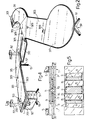
- Fig. 1 shows one of an almost infinite number of combinations possible with the modules that comprise the office furniture of the present invention.
- the basic element of all module combinations is a generally horizontal beam member 1.
- the beam member serves as the fundamental structural unit that ties all the modules into a rigid and integrated assembly.
- the beam members may be curved or straight. As many beams as desired may be combined into straight, curved, and laterally connected sections.
- the versatility of the beam member placement allows maximum flexibility for designing a furniture configuration that both follows the work flow and that satisfies workers' environmental needs.
- the beam members 1 are supported from the floor by a plurality of vertical supports 51.
- the vertical supports may be placed under and attached to the beam members at almost any location, thus complementing the flexibility of the beam members.
- Variations of the basic vertical support include the number and placement of the feet.
- vertical supports 53 have two feet.
- Vertical support 55 has one foot, and vertical support 57 comprises merely a vertical support column without feet.
- Fig. 1 illustrates six modular work surfaces 301 that may be rigidly connected to the beam members 1 at almost any convenient location.
- the work surfaces are designed in conjunction with the beam members to efficiently utilize the available office space while considering the psychological needs of the workers.
- the six work surfaces include four different modules; namely, two rectangular modules 303, two keyboard work surfaces 305, one round head work surface 307, and a keyboard surface 310 associated with each keyboard work surface 305.
- the work surfaces may be located in almost any location on the beam members, the edges of adjoining work surfaces normally abut.
- the work surfaces are shown with gaps therebetween for clarity, although it will be appreciated that non-abutting work surfaces are within the intention of the present invention.
- work surface modules are adapted to receive a variety of functional and attractive service modules.
- work surfaces 303 and 305 contain one or more identical openings into which an upstanding light module 151 or other module may be inserted. If a light or other module is not required, an attractive cover plate 309 is inserted into the work surface opening.
- the beam members 1 may also carry one or more file or storage cabinets 201.
- the cabinets are rigidly suspended from the beam members by modular suspension mechanisms 203.
- Keyboard surfaces 310 are suspended from the beam members in a manner similar to the suspension of the file cabinets.
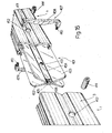
- Fig. 2 demonstrates the versatility of the modular furniture of the present invention.
- the beam members 1 underlie and support eight modular work surfaces 301. These include two rectangular work surfaces 303, a keyboard work surface 305, a semicircular work surface 311, a triangular wedge 313, a round wedge 315, a one-quarter circular work surface 317, and a keyboard surface 310. It will be noticed that the rectangular and keyboard work surfaces contain openings for service modules such as light modules 151 and 151', and the openings are covered by plates 309 if no service module is desired.
- Light module 151 supports a swingable telephone tray module 153.
- FIG. 2 two configurations of vertical supports are depicted.
- Vertical support 57 is a simple column.
- Vertical support 59 may include two, three, or four feet.
- One file cabinet 201 is shown in Fig. 2; it is suspended from the beam members by a suspension mechanism, not shown.
- Each beam member comprises a pair of parallel generally rectangular tubular beams 3 separated by and joined to generally U-shaped plates 5.
- the beams 3 may be straight or curved.
- the plates 5 are much shorter than the beams 3, so two or more plates are normally used with each pair of beams.
- the beams are fabricated with depressions 29 and 30 in the top and bottom walls, respectively.
- the preferred material for the beams and plates is steel, so the plates are typically welded to the beams. It will be noticed in Fig. 3 that the depth of the beams is relatively great in comparison to the width. That feature, together with the relatively thin-walled tubular construction, combines great bending stiffness in the vertical plane with light weight, thus contributing to the rigidity and versatility of the total assembly;
- a connector 7 has an opposed pair of four-sided tongues 9 that fit closely within the interior of the beams.
- the tongues extend from a central base 11 having a periphery that generally corresponds to the external dimensions of the beams.
- the tongues of connector 7 are inserted into adjoining beams, and the beams are drawn together until their ends strike opposite sides of the base 11.
- a headed key 13 is inserted through a slotted opening 15 in the top and bottom walls of each beam and a corresponding slot 17 in the tongues.
- the slots 17 taper inwardly from the opposite surfaces of the tongue.
- the tapers aid in creating a strong and rigid joint between adjoining beam members. To disassemble a joint for modifying a combination of beam members, it is necessary merely to remove keys 13 and pull the beams apart from connectors 7.
- FIG. 16 A second alternative way of joining two beam members 1 is illustrated in Fig. 16 where, as in Figs. 4 and 5, only one tubular beam 3 of each adjoining beam member is shown.
- two beam members 1 are connected to one another by means of a connector 401 having an expansible substantially X-shaped cross section and formed by two plates 402 and 403 having a substantially V-shaped cross section and arranged substantially in contact with one another and with their concavities facing outwards in opposite directions.
- Each of plates 402 and 403 includes a longitudinal middle flat portion 404 which is provided at one end with a recess 405 and at the other end with a protrusion 406.
- the recess 405 and the protrusion 406 of each of plates 401 and 402 engage the protrusion 406 and the recess 405 respectively of the other plate so as to fix longitudinally plates 402 and 403 relative to one another.
- Connector 401 fixed closely within the interior of the facing ends of the two beam members 2 with the longitudinal sides of plates 402 and 403 engaged within the longitudinal grooves defined by beam top end lower longitudinal depressions 29 and 30.
- Connector 401 is fixed longitudinally relative to beams 3 by means of an intermediate annular member 407 arranged between and in contact with the facing ends of beams 3 and engaging four lateral recesses, each of which is provided on a central portion of a respective longitudinal edge of the respective plate 402, 403.
- Annular member 407 consists in two C-shaped members 408 and 409 facing each other and connected to one another by means of two pin 410-and-socket 411 joints.
- Each beam 3 is laterally provided with a hole 412, facing the middle flat portion 404 of plate 403, where a respective coaxial threaded hole 413 is provided.
- Each hole 413 is engaged by a threaded pin 414 which may be operated from outside through the respective hole 412 to engage the middle flat portion 404 of plate 402 so as to expand connector 401 inside beams 3, and firmly connect beams 3 to one another.
- Figs. 6 and 7 disclose the lateral joining of two beam members 1 and l' at 90°.
- Two angle clamps 19, each having a tongue 21 and a jaw 23, are employed to rigidly join beam member 1' to beam member 1 at almost any desired location along the length of beam member 1.
- the tongues 21 are inserted into the interiors of the beams 3' until the ends of the beams strike angle clamp-Bhoulders 25.
- Keys 13 are employed to rigidly lock the angle clamps in the beams 3', as previously described for the longitudinal connectors 7.
- each jaw 23 is provided with a hook 27 for mating with beam top depression 29 and a foot 31 opposite the hook 27.
- Each foot contains a threaded opening into which a screw 33 is threaded.
- the screw is sized to fit beam lower depression 30. Tightening the screws 33 squeezes the beam between the hooks and screws, thus rigidly joining beam members 1 and 1'.
- Reference numeral 34 indicates a pencil tray that may be removably inserted between the beams 3 in a gap between adjoining work surfaces, such as shown in Fig. 1.
- Fig. 8 shows a lateral connector 35 for joining three beam members 1 that intersect at 120°.
- the connector includes three short beam members 36 and a three-legged plate 37 that is similar in vertical cross-section to U-shaped plate 5 (see Fig. 3).
- Each short beam member 36 is constructed by welding a plate 5 between two short sections 39 of standard beam configuration near one end of the sections. The other ends of the short beam sections are welded to the plate 37.
- the abutting ends are fabricated with bevels 43.
- the connection between the lateral connector 35 and beam members 1 are made as previously described, that is, by utilizing connectors 7 and keys 13 (see Figs. 4 and 5).
- a vertical support 51 will normally be placed under the connector 35.
- openings 45 are provided in the plate.
- a resilient decorative cap 49 shown in Fig. 14, is snapped in place over the beam open ends 50, as seen in Figs. 1 and 2.
- the construction of the vertical supports 51 for supporting the modular furniture of the present invention is illustrated in Figs. 9 and 10.
- the structural members that bear the weight of the beams 1 and work surfaces 301 include a pedestal 61, two columns 63, a yoke 65, and two brackets 66 and 67.
- the vertical support may also be provided with one or more feet 68.
- the preferred material for the vertical support structural members is aluminum.
- the column 63 is preferably constructed as a rectangular tube having relatively thin walls 69.
- the lower ends of the column walls fit snugly over upstanding rectangular projections 71 formed in the pedestal 61.
- the upper ends of the column walls fit snugly over downwardly extending rectangular projections 73 in yoke 65.
- a long screw 75 extends between the pedestal and the yoke, the yoke having a threaded opening to receive the screw threads.
- the yoke 65 includes a channel 76 defined by a pair of sides 77 and a floor 78.
- the sides 77 are joined by a strut 80 and have facing vertical surfaces 79 spaced apart a distance slightly greater than the spread between the outer vertical surfaces of beam member 1.
- the beam member rests on the floor 78 of strut 80 and fits rather loosely in channel 76.
- the yoke is constructed with two pairs of spaced vertical tabs 81 that project into corresponding spaced slots 47 in the bottom walls of beams 3; two tabs project into each beam.
- the slots 47 are similar to the slots 15 described previously for longitudinally joining two beam members; they are located at spaced intervals along the beams.
- a flat horizontal surface 83 is machined on the upper end of each side 77.
- the surfaces 83 provide support for brackets 66 and 67 through corresponding lower surfaces 85 on the brackets.
- the brackets 66 and 67 are of substantially identical construction except for the length of wing portions 91 and 93, respectively; therefore, a description of one bracket will be considered sufficient.
- the surfaces 85 are machined on the bottoms of sides 84,which have vertical surfaces 86 that correspond with yoke vertical surfaces 79.
- each bracket has a pair of downwardly extending tabs 87 that project from upper horizontal surface 88 into corresponding spaced slots 48 in the top walls of beams 3. Screws 89 join the yoke and brackets together.
- the beam member is restrained vertically between upper surface 88 and floor 78, and it is restrained longitudinally and laterally by tabs 81.
- the brackets are restrained vertically by surfaces 83 and screws 89, and they are restrained longitudinally and laterally by tabs 87. Screws 95 attach the work surface 301 to the bracket.
- the versatility of the modules allows a vertical support 51-to be located at the longitudinal junction of two beam members 1.
- the yoke 65 and brackets 66 and 67 are used in place of connectors 7 and keys 13, Figs. 4 and 5, for longitudinally joining two beam members in addition to vertically supporting the beam members.
- the vertical supports 51 may include one or more feet 68.
- the feet are manufactured as thin walled box-like structures, preferably of aluminum. If two feet are use, each is welded to a column 63 and thus serve the functional purpose of providing increased stability to the vertical support. If more than two feet are desired, two are welded to the column, and the additional feet are joined to pedestal 61 by a well known dovetail arrangement, not shown, for providing an attractive but non-functional appearance.
- Brackets 66 and 67 may be used with a modified yoke for supporting a work surface at points intermediate the vertical supports.
- the modified yoke is very similar to yoke 65, but the downward projections 73,are omitted, so that the lower contour of the yoke follows phantom line 96 of Fig. 9.
- the modules are designed to be esthetically pleasing.
- the structural members 63 and 68 are covered with two types of decorative sidings that greatly increase the attractiveness of the vertical supports.
- the first type of siding is a hollow columnar member 97 comprised of an upright section 99 and a foot section 101.
- the interior of the hollow upright section 99 is of a size and shape to fit over column 63, and foot section 101 fits over the top and sides of foot 68.
- Each interior wall 102 of the hollow section 99 terminates above and below, respectively, the projections 71 and 73 of pedestal 61 and yoke 65, respectively.
- the second type of decorative siding is relatively flat and extends the length of column 63; it is shown at reference numeral 103, Fig. 10.
- the siding 103 includes hooks 105 protruding into the interior 107 of the vertical support.
- the hooks 105 flexibly latch onto shoulders 109 formed on the interior sides of hollow siding 97.
- the sidings 103 are recessed into steps 111 of the sidings 97 and corresponding steps in the yoke 65. If three or four feet are desired, the non-functional feet are encased in a decorative siding similar to foot section 101. Siding 103 is then modified to terminate at the upper surface of the non-functional foot siding section.
- the decorative exterior surfaces of sidings 97 and 103 may be in the form of flutes 113.
- the preferred material for the decorative sidings is a strong but flexible plastic.
- the work surfaces 301 can be of a wide variety of sizes and shapes, as best shown in Figs. 1 and 2. All work surfaces, however, are mounted to the beam members 1 by yoke 65 or a modified yoke and by brackets 66 and 67, as previously described and as illustrated in Figs. 9 and 10.
- the work surfaces are manufactured from attractive and functional materials, including smoked glass, wood, and plastic laminate.
- a particularly attractive work surface is composed of a plastic laminate with a removable decorative half- round wood edging 319 that fastens to the work surface edges by means of dowels 321 and corresponding holes, as illustrated in Fig. 13.
- the beam members 1 are sufficiently strong and stiff to support file cabinet 201 suspended therefrom, Figs. 1 and 2.
- the suspension mechanism 203 is best illustrated in Figs. 11 and 12.
- Each beam 3 supports a suspension member 205 having a hook 207 at the upper end thereof.
- the suspension member is constructed with a ledge 209 having a generally vertical opening therein for receiving screw 211. The head of the screw bears against the ledge.
- the screw threads engage a transverse threaded opening in a pin 213 having grooves 214 that are received in clearance slots 215 in spaced apart legs 217 of the suspension member.
- the pin 213 is also received in openings 219 in the vertical walls of a channel 221.
- the bottom wall 223 of the channel is fastened to the top wall 225 of cabinet 201 by conventional fasteners such as screw and nut 227.
- the cabinet is fastened to the channel 221. Pins 213 are inserted through the channel openings 219. Hooks 207 are placed in the top depressions 29 of beams 3.
- the cabinet is raised by any convenient method to within a short distance of the underside of the beam member 1 so that the slots 215 of suspension member 205 are placed over the pin grooves 214.
- a screw 211 is then inserted through the opening in ledge 209 of each suspension member to engage the threads in the corresponding pin. Tightening the screws draws the channel and cabinet upward until the top surface 229 of the channel contacts the underside of the beam member. At that point, further tightening of the screws will"rigidly join the suspension mechnaism to the beam member.
- the cabinet may be easily relocated to another location along the beam member by loosening screws 211 a slight amount and sliding the cabinet and suspension mechanism along the beam member to the new location. Retightening the screws will again rigidly join the cabinet to the beam member.
- a slight modification to the suspension mechanism 203 of Figs. 11 and 12 enables the beam member 1 to suspend a keyboard surface 310 therefrom.
- the keyboard surface is used in conjunction with a keyboard work surface 305.
- the versatility of the modules of the present invention permits horizontal placement of the keyboard surface at almost any desired relationship to the keyboard work surface.
- the beam member 1 is shown with suspension members 205, pins 213, and an elongated channel 231.
- the channel 231 extends substantially beyond the beam member to support keyboard surface 310 which is secured at the desired location by conventional fasteners 233.
- the keyboard work surface is indicated at 305, together with decorative edging 319.
- brackets 66 and 67 and the modified yoke described previously in conjunction with the mounting of the beam member on vertical supports 51 see Figs. 9 and 10).
- some work surfaces 301 contain openings that are adapted to receive small upstanding service modules.
- a light module 151 is mounted in one of the keyboard work surfaces 305.
- light module 151 is mounted in rectangular work surface 303; the light module includes a swingable telephone tray 153.
- Other modules, all with interchangeable connections to the work surfaces, include telephone trays and work baskets.
- a light module may contain a radio and/or a clock.
- Figs. 14-15 the apparatus for mounting the light module 151 is shown in detail. It will be understood that the light module is merely exemplary; other upstanding modules employ the same apparatus.
- a notch 155 is cut into the work surface 301 from one end.
- the notch is grooved along opposite sides at 157.
- a thin-walled four-sided shell 159 having tongues 161 corresponding to grooves 157, is pushed into the notch before the decorative edging 319 is applied.
- a column base 163 having four vertical sides 164 and a top wall 165 is resiliently pressed into the shell 159.
- the wall 165 includes two parallel ridges 167 extending upwardly from the top surface thereof.
- Column 169 of the module 151 is fabricated as a three-sided thin-walled member that locates over ridges 167. The open side of column 169 is covered with a snap-on cover 168.
- the interior of the two opposite walls of column 169 are fabricated with opposed grooves 170, Fig. 16, for receiving ears 171 of a rectangular tube 173.
- the height of tube 173 may be adjusted within the column.
- the tube contains a pair of threaded holes for receiving screws 175. Turning screws 175 against the back wall 176 of the column locks the tube to the column.
- a screw 177 is inserted vertically through the tube and through an opening 178 in wall 165 and is threaded into a threaded bar 179 captured in a channel 181.
- the bar 179 and channel 181 span the notch 155 in the work surface 301, Fig. 14.
- the column 169 may support a telephone module 153 or other productivity enhancing devices.
- the module 153 is adjustably mounted to the column 169 by tube 183 having ears 171 1 that slide in grooves 170. Tightening screws 175 1 locks the tube 183_to the column at the desired height.
- the tube includes a lug 185 projecting therefrom that pivotally supports, such as by a shoulder screw and nut 187, a clevice 189.
- the clevice may be configured to mount a receptacle 191 for commonly used office items, such as telephones and papers.
- the notches 155 are covered with decorative cover plates 309, Figs. 1 and 2.
- the cover plates are very similar to the column base 163, but they lack the ridges 167 and opening 178.
- the cover plates may be provided with a decorative hinged cover 193 if passage of wires through the cover plate is desired, as will be explained hereinafter.
- the cover 168, column 169, column base 163, hinged cover 193, and cover plate 309 are of the same color plastic material as the decorative sidings 97 and 103 of the vertical supports. Moreover, the surface textures, as for example, the flutes 113 shown in conjunction with the sidings 97 and 103 of Fig. 10, are similarly incorporated into the light module components 168, 169, 163, 193, and 309.
- Pursuant to the present invention provision is made for the neat and efficient management of the electrical and control wiring used in connection with the office furniture. This is accomplished by hiding the wiring within the furniture modules while supplying them to the required location.
- wiring from the office outlets enter the modular furniture assembly of the present invention through an opening in a vertical support 51.
- the wiring may enter vertical support 53 in Fig. 1 through an opening 115 in the lower end of decorative siding 103, Fig. 10.
- a plastic four-lobed wire divider 259 is employed. Separation of wires is important if, for example, wires for 120 volt A.C. power and for computer data transmission are required at the furniture assembly.
- the wire divider 259 has a hollow central opening to receive the vertical support tie screw 75. The wires pass beside strut 80 of yoke 65 to enter channel 76, Fig. 9, and thence along the beam members 1.
- plastic wire tray 261 is shown carried by the plates 5 of beam members 1.
- the wire tray illustrated contains four ducts 263 that are open at the top. Since the work surfaces 301 are normally the last modules assembled, the wires 251, 253, 255, and 257 may be easily installed in the wire trays from above, thus eliminating the necessity of pulling the wires through closed conduits.
- wire 257 may be a power wire for the lamp 200 of light module 151 (see Figs. 1 and 2).
- Wire 257 runs from tray 261 through the work surface notch 155, passes through column base opening 178, and rises to the conventional terminals, not illustrated, of the lamp 200. Similar wiring configurations are used for radio, clock, and telephone services.
- the column base 163 also serves as a convenient and attractive means for passing wires from the beam member to the. point of use on the work surface.
- a three-sided hinged cover 193 pivots within the column base about a horizontal axis by means of pins and holes of well-known construction, not shown in Figs. 14 and 16.
- the cover 193 comprises a decorative lid 195 and two sides 197.
- cover 193 may be opened sufficiently to pass a wire, as at 199, from the beam member 1 to the top of work surface 301. If no wire is present, the cover is closed so the lid 195 is flush with the column base and work surface.
- a male plug 264 on the end of an electrical cord,as at 199.
- a conventional socket 265, Fig. 14 may be installed on top of tray 261 within the beam member 1.
- the use of an extensible cord 267 allows the same socket module to be employed for all work surfaces 301.
- the extensible cord leads to a common junction, now shown, located within the beam member near the vertical support that receives the wires from the office outlets.
Landscapes
- Tables And Desks Characterized By Structural Shape (AREA)
- Furniture Connections (AREA)
- Combinations Of Kitchen Furniture (AREA)
- Details Of Television Scanning (AREA)
- Lubrication Of Internal Combustion Engines (AREA)
- Liquid Crystal Substances (AREA)
Abstract
Description
- This invention pertains to furniture, and more particularly to modular office furniture.
- After years of designing office furnishings and equipment on a purely functional basis, designers are discovering that using advanced technology does not necessarily result in maximum productivity. Rather, people are most productive when, in addition to using modern furniture and equipment, they are motivated by proper psychophysical conditions. Thus, the office functional aspect, although necessary, is not sufficient.
- It is well known that human behavior is influenced by environmental conditions. Modern office designers must solve functional problems, but they also must create conditions that psychologically encourage worker productivity. This may be achieved by giving each worker a feeling of security and importance, both as an individual and as a member of the group to which he belongs.
- The principal task of the furniture designer is to create a personal workplace or "habitat" that avoids uniformity and monotony. At the same time, the furniture must be flexible in order to assure maximum freedom in organizing a work area. In short, the furniture must be designed to adapt the workplace to the individual in any office space.
- The office furniture of the present invention assures a very high degree of freedom in the placement of the furniture within an office space. This is accomplished by designing and manufacturing the furniture components in a number of interchangeable and interconnectible modules. While offering all the advantages of modular construction, the furniture of the present invention also provides maximum independence for the working persons, both individually and collectively. To further enhance the phychological well being of the workers, the modules are esthetically pleasing.
- In accordance with the present invention, the basic element of the modular construction is a structural beam member with integrated wire management. To suit both the work flow requirements and human factors, several beam members may be rigidly joined together longitudinally and/or laterally by suitable connectors to create the best arrangement possible to suit the circumstances at hand. The beam members include wireways for bringing electrical power and control wires to the point of use in an efficient and unobtrusive manner..
- The beam members are supported by as many modular vertical supports as necessary. The vertical supports may be placed at almost any location under the beams. The vertical supports include a variety of attractive foot configurations that suit both the placement of the supports and esthetic requirements. The vertical supports are rigidly fastened to the beam members by sturdy and easy assemblable modular yokes and brackets. The vertical supports include ducts for bringing the electrical power and control services from the room outlet to the horizontal beam members, thus eliminating wires dangling over the edges of the work surfaces.
- The work surfaces are available in several modular sizes and shapes. They are designed to suit the beam configurations to which they are rigidly mounted by modular yokes and-brackets. The work surface modules are manufactured in a variety of attractive materials, including wood, glass, and plastic laminate. To minimize the exposure of wiring to electrical equipment, the work surfaces contain conveniently located outlets for passing the wires from the beam members to the equipment.
- The modular construction of the furniture of the present invention includes storage and file cabinets that are rigidly suspended from the beam members by modular suspension components. The cabinets may be placed at almost any convenient location along the beam members. They are manufactured in various sizes, shapes, and materials.
- The office furniture of the present invention also includes numerous attractive modular accessories, such as data processing work stations, lazy susans, electrical service modules, light stands, telephone trays, and paper baskets. The modular construction of the furniture components allows great flexibility in combining the various components into the most attractive and functional configuration possible for the office space available. The rigidity of the beam members and other structural components assures that the furniture system provides stable and pleasing work stations. Further, the modular construction allows rapid and easy alteration to suit changing work and personnel requirements.
- Other objects and advantages of the invention will become apparent from the disclosure.
-
- Fig. 1 is a partially exploded perspective view of a typical combination of modules of the office furniture of the present invention;
- Fig. 2 is a perspective view of an alternate combination of furniture modules;
- Fig. 3 is a sectional view taken along
lines 3--3 of Fig. 1; - Fig. 4 is a top view of a longitudinal joint between two beams of the present invention;
- Fig. 5 is a sectional view taken along
lines 5--5 of Fig. 4; - Fig. 6 is a top view of a lateral joint between two modular beam members;
- Fig. 7 is a sectional view taken along
lines 7--7 of Fig. 6; - Fig. 8 is a top view of a lateral connection between three modular beam members;
- Fig. 9 is a sectional view through a typical combination of components comprising a vertical support of the present invention;
- Fig. 10 is a sectional view taken along lines 10--10 of Fig. 9;
- Fig. 11 is a sectional view taken along lines 11-11 of Fig. 1;
- Fig. 12 is a view taken along lines 12--12 of Fig. 11;
- Fig. 13 is a sectional view taken along
lines 13--13 of Fig. 1; - Fig. 14 is a sectional view taken along lines 14--14 of Fig. 2;
- Fig. 15 is a sectional view taken along
lines 15--15 of Fig. 14; and - Fig. 16 is a perspective exploded view of a nother embodiment of a longitudinal joint between two beams of the present invention.
- Although the disclosure hereof is detailed and exact to enable those skilled in the art to practice the invention, the physical embodiments herein disclosed merely exemplify the invention which may be embodied in other specific structure. The scope of the invention is defined in the claims appended hereto.
- Fig. 1 shows one of an almost infinite number of combinations possible with the modules that comprise the office furniture of the present invention. The basic element of all module combinations is a generally
horizontal beam member 1. The beam member serves as the fundamental structural unit that ties all the modules into a rigid and integrated assembly. The beam members may be curved or straight. As many beams as desired may be combined into straight, curved, and laterally connected sections. The versatility of the beam member placement allows maximum flexibility for designing a furniture configuration that both follows the work flow and that satisfies workers' environmental needs. - The
beam members 1 are supported from the floor by a plurality of vertical supports 51. The vertical supports may be placed under and attached to the beam members at almost any location, thus complementing the flexibility of the beam members. Variations of the basic vertical support include the number and placement of the feet. For example,vertical supports 53 have two feet.Vertical support 55 has one foot, andvertical support 57 comprises merely a vertical support column without feet. - Fig. 1 illustrates six
modular work surfaces 301 that may be rigidly connected to thebeam members 1 at almost any convenient location. The work surfaces are designed in conjunction with the beam members to efficiently utilize the available office space while considering the psychological needs of the workers. In Fig. 1, the six work surfaces include four different modules; namely, tworectangular modules 303, two keyboard work surfaces 305, one roundhead work surface 307, and akeyboard surface 310 associated with eachkeyboard work surface 305. Although the work surfaces may be located in almost any location on the beam members, the edges of adjoining work surfaces normally abut. In Fig. 1, the work surfaces are shown with gaps therebetween for clarity, although it will be appreciated that non-abutting work surfaces are within the intention of the present invention. - Some work surface modules are adapted to receive a variety of functional and attractive service modules. For example, work surfaces 303 and 305 contain one or more identical openings into which an
upstanding light module 151 or other module may be inserted. If a light or other module is not required, anattractive cover plate 309 is inserted into the work surface opening. - In addition to supporting the work surfaces 301, the
beam members 1 may also carry one or more file orstorage cabinets 201. The cabinets are rigidly suspended from the beam members bymodular suspension mechanisms 203. Keyboard surfaces 310 are suspended from the beam members in a manner similar to the suspension of the file cabinets. - Fig. 2 demonstrates the versatility of the modular furniture of the present invention. The
beam members 1 underlie and support eight modular work surfaces 301. These include two rectangular work surfaces 303, akeyboard work surface 305, asemicircular work surface 311, atriangular wedge 313, around wedge 315, a one-quartercircular work surface 317, and akeyboard surface 310. It will be noticed that the rectangular and keyboard work surfaces contain openings for service modules such aslight modules 151 and 151', and the openings are covered byplates 309 if no service module is desired.Light module 151 supports a swingabletelephone tray module 153. - In Fig. 2, two configurations of vertical supports are depicted.
Vertical support 57 is a simple column.Vertical support 59 may include two, three, or four feet. Onefile cabinet 201 is shown in Fig. 2; it is suspended from the beam members by a suspension mechanism, not shown. - Turning now to Fig. 3, the construction of the
modular beam members 1 will be described. Each beam member comprises a pair of parallel generally rectangulartubular beams 3 separated by and joined to generallyU-shaped plates 5. Thebeams 3 may be straight or curved. Preferably, theplates 5 are much shorter than thebeams 3, so two or more plates are normally used with each pair of beams. In the illustrated embodiment, the beams are fabricated withdepressions - A first way of joining two
beam members 1 is illustrated in Figs. 4 and 5. Only onetubolar beam 3 of each adjoining beam member is shown, because bothbeams 3 are joined in the same fashion. Aconnector 7 has an opposed pair of four-sided tongues 9 that fit closely within the interior of the beams. The tongues extend from acentral base 11 having a periphery that generally corresponds to the external dimensions of the beams. To connect two beam members longitudinally, the tongues ofconnector 7 are inserted into adjoining beams, and the beams are drawn together until their ends strike opposite sides of thebase 11. To securely lock the beams to the connector, a headedkey 13 is inserted through a slottedopening 15 in the top and bottom walls of each beam and acorresponding slot 17 in the tongues. Theslots 17 taper inwardly from the opposite surfaces of the tongue. The tapers aid in creating a strong and rigid joint between adjoining beam members. To disassemble a joint for modifying a combination of beam members, it is necessary merely to removekeys 13 and pull the beams apart fromconnectors 7. - A second alternative way of joining two
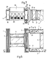
beam members 1 is illustrated in Fig. 16 where, as in Figs. 4 and 5, only onetubular beam 3 of each adjoining beam member is shown. - In the embodiment shown in Fig. 16, two
beam members 1 are connected to one another by means of aconnector 401 having an expansible substantially X-shaped cross section and formed by twoplates - Each of
plates flat portion 404 which is provided at one end with a recess 405 and at the other end with aprotrusion 406. The recess 405 and theprotrusion 406 of each ofplates protrusion 406 and the recess 405 respectively of the other plate so as to fixlongitudinally plates -
Connector 401 fixed closely within the interior of the facing ends of the two beam members 2 with the longitudinal sides ofplates longitudinal depressions Connector 401 is fixed longitudinally relative tobeams 3 by means of an intermediateannular member 407 arranged between and in contact with the facing ends ofbeams 3 and engaging four lateral recesses, each of which is provided on a central portion of a respective longitudinal edge of therespective plate Annular member 407 consists in two C-shapedmembers socket 411 joints. - Each
beam 3 is laterally provided with ahole 412, facing the middleflat portion 404 ofplate 403, where a respective coaxial threadedhole 413 is provided. - Each
hole 413 is engaged by a threadedpin 414 which may be operated from outside through therespective hole 412 to engage the middleflat portion 404 ofplate 402 so as to expandconnector 401inside beams 3, and firmly connectbeams 3 to one another. - Figs. 6 and 7 disclose the lateral joining of two
beam members 1 and l' at 90°. Two angle clamps 19, each having atongue 21 and ajaw 23, are employed to rigidly join beam member 1' tobeam member 1 at almost any desired location along the length ofbeam member 1. Thetongues 21 are inserted into the interiors of the beams 3' until the ends of the beams strike angle clamp-Bhoulders 25.Keys 13 are employed to rigidly lock the angle clamps in the beams 3', as previously described for thelongitudinal connectors 7. To secure the angle clamps and beam member 1' tobeam member 1, eachjaw 23 is provided with ahook 27 for mating with beamtop depression 29 and afoot 31 opposite thehook 27. Each foot contains a threaded opening into which ascrew 33 is threaded. The screw is sized to fit beamlower depression 30. Tightening thescrews 33 squeezes the beam between the hooks and screws, thus rigidly joiningbeam members 1 and 1'. -
Reference numeral 34 indicates a pencil tray that may be removably inserted between thebeams 3 in a gap between adjoining work surfaces, such as shown in Fig. 1. - Fig. 8 shows a
lateral connector 35 for joining threebeam members 1 that intersect at 120°. The connector includes threeshort beam members 36 and a three-legged plate 37 that is similar in vertical cross-section to U-shaped plate 5 (see Fig. 3). Eachshort beam member 36 is constructed by welding aplate 5 between twoshort sections 39 of standard beam configuration near one end of the sections. The other ends of the short beam sections are welded to theplate 37. To enable theshort beam members 36 to interfit with one another in a neat fashion, the abutting ends are fabricated withbevels 43. The connection between thelateral connector 35 andbeam members 1 are made as previously described, that is, by utilizingconnectors 7 and keys 13 (see Figs. 4 and 5). - It is contemplated that a
vertical support 51 will normally be placed under theconnector 35. To allow wires to pass from the vertical support to the beam members, as will be described fully hereinafter,openings 45 are provided in the plate. Although not described in detail herein, it will be apparent that a lateral connector for joining four beam members that intersect at 90° falls within the intent of the present invention. - To enhance the appearance of the
beam members 1, a resilientdecorative cap 49, shown in Fig. 14, is snapped in place over the beam open ends 50, as seen in Figs. 1 and 2. - The construction of the
vertical supports 51 for supporting the modular furniture of the present invention is illustrated in Figs. 9 and 10. The structural members that bear the weight of thebeams 1 andwork surfaces 301 include apedestal 61, twocolumns 63, ayoke 65, and twobrackets more feet 68. The preferred material for the vertical support structural members is aluminum. - The
column 63 is preferably constructed as a rectangular tube having relativelythin walls 69. The lower ends of the column walls fit snugly over upstandingrectangular projections 71 formed in thepedestal 61. The upper ends of the column walls fit snugly over downwardly extendingrectangular projections 73 inyoke 65. To tie the yoke, pedestal and columns into a unitary structure, along screw 75 extends between the pedestal and the yoke, the yoke having a threaded opening to receive the screw threads. - The
yoke 65 includes achannel 76 defined by a pair ofsides 77 and a floor 78. Thesides 77 are joined by astrut 80 and have facingvertical surfaces 79 spaced apart a distance slightly greater than the spread between the outer vertical surfaces ofbeam member 1. Thus, the beam member rests on the floor 78 ofstrut 80 and fits rather loosely inchannel 76. To rigidly locate the yoke longitudinally and laterally in the beam member, the yoke is constructed with two pairs of spacedvertical tabs 81 that project into corresponding spacedslots 47 in the bottom walls ofbeams 3; two tabs project into each beam. Theslots 47 are similar to theslots 15 described previously for longitudinally joining two beam members; they are located at spaced intervals along the beams. - A flat horizontal surface 83 is machined on the upper end of each
side 77. The surfaces 83 provide support forbrackets lower surfaces 85 on the brackets. Thebrackets wing portions surfaces 85 are machined on the bottoms ofsides 84,which havevertical surfaces 86 that correspond with yoke vertical surfaces 79. To laterally and longitudinally position the brackets tobeam member 1, each bracket has a pair of downwardly extendingtabs 87 that project from upperhorizontal surface 88 into corresponding spacedslots 48 in the top walls ofbeams 3.Screws 89 join the yoke and brackets together. Thus, the beam member is restrained vertically betweenupper surface 88 and floor 78, and it is restrained longitudinally and laterally bytabs 81. The brackets are restrained vertically by surfaces 83 and screws 89, and they are restrained longitudinally and laterally bytabs 87.Screws 95 attach thework surface 301 to the bracket. - The versatility of the modules allows a vertical support 51-to be located at the longitudinal junction of two
beam members 1. To accomplish that, theyoke 65 andbrackets connectors 7 andkeys 13, Figs. 4 and 5, for longitudinally joining two beam members in addition to vertically supporting the beam members. - If desired, the
vertical supports 51 may include one ormore feet 68. In the illustrated embodiment, the feet are manufactured as thin walled box-like structures, preferably of aluminum. If two feet are use, each is welded to acolumn 63 and thus serve the functional purpose of providing increased stability to the vertical support. If more than two feet are desired, two are welded to the column, and the additional feet are joined topedestal 61 by a well known dovetail arrangement, not shown, for providing an attractive but non-functional appearance. - Although the present invention provides great flexibility in the placement of the
vertical supports 51, the attachment of awork surface 301 to abeam member 1 is not limited to vertical support locations.Brackets yoke 65, but thedownward projections 73,are omitted, so that the lower contour of the yoke followsphantom line 96 of Fig. 9. - Further in accordance with the present invention, the modules are designed to be esthetically pleasing. In the preferred construction of the
vertical supports 51, thestructural members hollow columnar member 97 comprised of anupright section 99 and afoot section 101. The interior of thehollow upright section 99 is of a size and shape to fit overcolumn 63, andfoot section 101 fits over the top and sides offoot 68. Each interior wall 102 of thehollow section 99 terminates above and below, respectively, theprojections pedestal 61 andyoke 65, respectively. The second type of decorative siding is relatively flat and extends the length ofcolumn 63; it is shown at reference numeral 103, Fig. 10. The siding 103 includes hooks 105 protruding into the interior 107 of the vertical support. The hooks 105 flexibly latch onto shoulders 109 formed on the interior sides ofhollow siding 97. To further enhance the appearance of the vertical supports, the sidings 103 are recessed into steps 111 of thesidings 97 and corresponding steps in theyoke 65. If three or four feet are desired, the non-functional feet are encased in a decorative siding similar tofoot section 101. Siding 103 is then modified to terminate at the upper surface of the non-functional foot siding section. - Merely by way of illustration, the decorative exterior surfaces of
sidings 97 and 103 may be in the form offlutes 113. The preferred material for the decorative sidings is a strong but flexible plastic. - To serve both functional and environmental purposes, the work surfaces 301 can be of a wide variety of sizes and shapes, as best shown in Figs. 1 and 2. All work surfaces, however, are mounted to the
beam members 1 byyoke 65 or a modified yoke and bybrackets dowels 321 and corresponding holes, as illustrated in Fig. 13. - The
beam members 1 are sufficiently strong and stiff to supportfile cabinet 201 suspended therefrom, Figs. 1 and 2. Thesuspension mechanism 203 is best illustrated in Figs. 11 and 12. Eachbeam 3 supports asuspension member 205 having ahook 207 at the upper end thereof. The suspension member is constructed with aledge 209 having a generally vertical opening therein for receivingscrew 211. The head of the screw bears against the ledge. The screw threads engage a transverse threaded opening in apin 213 havinggrooves 214 that are received inclearance slots 215 in spaced apartlegs 217 of the suspension member. Thepin 213 is also received inopenings 219 in the vertical walls of achannel 221. Thebottom wall 223 of the channel is fastened to thetop wall 225 ofcabinet 201 by conventional fasteners such as screw and nut 227. - To suspend the
file cabinet 201 from thebeam member 1, the cabinet is fastened to thechannel 221.Pins 213 are inserted through thechannel openings 219.Hooks 207 are placed in thetop depressions 29 ofbeams 3. The cabinet is raised by any convenient method to within a short distance of the underside of thebeam member 1 so that theslots 215 ofsuspension member 205 are placed over thepin grooves 214. Ascrew 211 is then inserted through the opening inledge 209 of each suspension member to engage the threads in the corresponding pin. Tightening the screws draws the channel and cabinet upward until thetop surface 229 of the channel contacts the underside of the beam member. At that point, further tightening of the screws will"rigidly join the suspension mechnaism to the beam member. - The cabinet may be easily relocated to another location along the beam member by loosening screws 211 a slight amount and sliding the cabinet and suspension mechanism along the beam member to the new location. Retightening the screws will again rigidly join the cabinet to the beam member.
- A slight modification to the
suspension mechanism 203 of Figs. 11 and 12 enables thebeam member 1 to suspend akeyboard surface 310 therefrom. As shown in Figs. 1 and 2, the keyboard surface is used in conjunction with akeyboard work surface 305. The versatility of the modules of the present invention permits horizontal placement of the keyboard surface at almost any desired relationship to the keyboard work surface. Referring to Fig. 13, thebeam member 1 is shown withsuspension members 205, pins 213, and anelongated channel 231. Thechannel 231 extends substantially beyond the beam member to supportkeyboard surface 310 which is secured at the desired location byconventional fasteners 233. The keyboard work surface is indicated at 305, together withdecorative edging 319. Also shown in Fig. 13 arebrackets - As shown in Figs. 1 and 2, some
work surfaces 301 contain openings that are adapted to receive small upstanding service modules. For example, in Fig. 1, alight module 151 is mounted in one of the keyboard work surfaces 305. In Fig. 2,light module 151 is mounted inrectangular work surface 303; the light module includes aswingable telephone tray 153. Other modules, all with interchangeable connections to the work surfaces, include telephone trays and work baskets. As a further example of the versatility of the modules, a light module may contain a radio and/or a clock. - Turning to Figs. 14-15, the apparatus for mounting the
light module 151 is shown in detail. It will be understood that the light module is merely exemplary; other upstanding modules employ the same apparatus. - A
notch 155 is cut into thework surface 301 from one end. The notch is grooved along opposite sides at 157. A thin-walled four-sided shell 159, havingtongues 161 corresponding togrooves 157, is pushed into the notch before thedecorative edging 319 is applied. Acolumn base 163 having fourvertical sides 164 and atop wall 165 is resiliently pressed into theshell 159. Thewall 165 includes twoparallel ridges 167 extending upwardly from the top surface thereof.Column 169 of themodule 151 is fabricated as a three-sided thin-walled member that locates overridges 167. The open side ofcolumn 169 is covered with a snap-oncover 168. The interior of the two opposite walls ofcolumn 169 are fabricated withopposed grooves 170, Fig. 16, for receivingears 171 of arectangular tube 173. The height oftube 173 may be adjusted within the column. The tube contains a pair of threaded holes for receivingscrews 175. Turningscrews 175 against theback wall 176 of the column locks the tube to the column. To anchor the column in place on the column base, a screw 177 is inserted vertically through the tube and through an opening 178 inwall 165 and is threaded into a threadedbar 179 captured in achannel 181. Thebar 179 andchannel 181 span thenotch 155 in thework surface 301, Fig. 14. - To aid combining functionality with a pleasing environment, the
column 169 may support atelephone module 153 or other productivity enhancing devices. As shown in Fig. 14, themodule 153 is adjustably mounted to thecolumn 169 bytube 183 havingears 1711 that slide ingrooves 170. Tighteningscrews 1751 locks the tube 183_to the column at the desired height. The tube includes alug 185 projecting therefrom that pivotally supports, such as by a shoulder screw andnut 187, aclevice 189. The clevice may be configured to mount areceptacle 191 for commonly used office items, such as telephones and papers. - If a service module is not desired, the
notches 155 are covered withdecorative cover plates 309, Figs. 1 and 2. The cover plates are very similar to thecolumn base 163, but they lack theridges 167 and opening 178. The cover plates may be provided with a decorative hingedcover 193 if passage of wires through the cover plate is desired, as will be explained hereinafter. - In keeping with the esthetic qualities of the present invention, the
cover 168,column 169,column base 163, hingedcover 193, andcover plate 309 are of the same color plastic material as thedecorative sidings 97 and 103 of the vertical supports. Moreover, the surface textures, as for example, theflutes 113 shown in conjunction with thesidings 97 and 103 of Fig. 10, are similarly incorporated into thelight module components - Pursuant to the present invention, provision is made for the neat and efficient management of the electrical and control wiring used in connection with the office furniture. This is accomplished by hiding the wiring within the furniture modules while supplying them to the required location.
- In the preferred construction, wiring from the office outlets enter the modular furniture assembly of the present invention through an opening in a
vertical support 51. For example, the wiring may entervertical support 53 in Fig. 1 through anopening 115 in the lower end of decorative siding 103, Fig. 10. To aid in separating thewires lobed wire divider 259 is employed. Separation of wires is important if, for example, wires for 120 volt A.C. power and for computer data transmission are required at the furniture assembly. Thewire divider 259 has a hollow central opening to receive the verticalsupport tie screw 75. The wires pass besidestrut 80 ofyoke 65 to enterchannel 76, Fig. 9, and thence along thebeam members 1. - Turning once again to Fig. 3,
plastic wire tray 261 is shown carried by theplates 5 ofbeam members 1. The wire tray illustrated contains fourducts 263 that are open at the top. Since the work surfaces 301 are normally the last modules assembled, thewires - In Fig. 14,
wire 257 may be a power wire for thelamp 200 of light module 151 (see Figs. 1 and 2).Wire 257 runs fromtray 261 through thework surface notch 155, passes through column base opening 178, and rises to the conventional terminals, not illustrated, of thelamp 200. Similar wiring configurations are used for radio, clock, and telephone services. - Besides supporting
column 169, thecolumn base 163 also serves as a convenient and attractive means for passing wires from the beam member to the. point of use on the work surface. For that purpose, a three-sided hingedcover 193 pivots within the column base about a horizontal axis by means of pins and holes of well-known construction, not shown in Figs. 14 and 16. Thecover 193 comprises adecorative lid 195 and twosides 197. Thus, cover 193 may be opened sufficiently to pass a wire, as at 199, from thebeam member 1 to the top ofwork surface 301. If no wire is present, the cover is closed so thelid 195 is flush with the column base and work surface. - Many office electrical appliances, as for example, typewriters, are provided with a
male plug 264 on the end of an electrical cord,as at 199. To provide power for the appliances in a neat and convenient fashion, aconventional socket 265, Fig. 14, may be installed on top oftray 261 within thebeam member 1. The use of anextensible cord 267 allows the same socket module to be employed for all work surfaces 301. The extensible cord leads to a common junction, now shown, located within the beam member near the vertical support that receives the wires from the office outlets. - Thus, it is apparent that there has been provided, in accordance with the invention, modular office furniture with integrated wire management that fully satisfies the objects, aims, and advantages set forth above. While the invention has been described in conjunction with specific embodiments thereof, it is evident that many elternatives, modifications, and variations will be apparent to those skilled in the art in light of the foregoing description. Accordingly, it is intended to embrace all such alternatives, modifications, and variations as fall within the spirit and broad scope of the appended claims.
Claims (26)
so that the modules may be rigidly combined into a great number of patterns to suit the office work and personnel requirements.
Priority Applications (1)
| Application Number | Priority Date | Filing Date | Title |
|---|---|---|---|
| AT84103953T ATE48077T1 (en) | 1983-04-22 | 1984-04-09 | KIT FURNITURE SYSTEM. |
Applications Claiming Priority (4)
| Application Number | Priority Date | Filing Date | Title |
|---|---|---|---|
| IT485083U | 1983-04-22 | ||
| IT8304850U IT8304850V0 (en) | 1983-04-22 | 1983-04-22 | OFFICE MOBILE OF THE TYPE WITH MULTIPLE WORKPLACES |
| IT500683U | 1983-10-06 | ||
| ITBV1983U5006U IT8305006U1 (en) | 1983-10-06 | 1983-10-06 | CONNECTION SYSTEM BETWEEN TWO COAXIAL HOLLOW BARS WITH A SUBSTANTIALLY RECTANGULAR SECTION. |
Publications (3)
| Publication Number | Publication Date |
|---|---|
| EP0123972A2 true EP0123972A2 (en) | 1984-11-07 |
| EP0123972A3 EP0123972A3 (en) | 1986-01-22 |
| EP0123972B1 EP0123972B1 (en) | 1989-11-23 |
Family
ID=26325601
Family Applications (1)
| Application Number | Title | Priority Date | Filing Date |
|---|---|---|---|
| EP84103953A Expired EP0123972B1 (en) | 1983-04-22 | 1984-04-09 | Modular furniture |
Country Status (6)
| Country | Link |
|---|---|
| EP (1) | EP0123972B1 (en) |
| AU (1) | AU578018B2 (en) |
| BR (1) | BR6400573U (en) |
| DE (1) | DE3480521D1 (en) |
| ES (1) | ES288254Y (en) |
| NO (1) | NO160759C (en) |
Cited By (17)
| Publication number | Priority date | Publication date | Assignee | Title |
|---|---|---|---|---|
| GB2178951A (en) * | 1985-07-31 | 1987-02-25 | Concepts International | Infill panel |
| EP0182662A3 (en) * | 1984-11-20 | 1987-04-22 | Hauserman Inc. | Space divider system |
| US4798423A (en) * | 1985-11-01 | 1989-01-17 | Lacour Incorporated | Modular desk system |
| EP0362614A3 (en) * | 1988-10-03 | 1990-06-20 | Voko Franz Vogt & Co. | Work place device |
| DE9012759U1 (en) * | 1990-09-07 | 1991-01-03 | Dyes GmbH Büromöbelfabrik, 3252 Bad Münder | Office furniture with a crossbar |
| DE4028452A1 (en) * | 1990-09-07 | 1992-03-12 | Dyes Bueromoebelwerk | TABLE BASE FOR A WORK OR OFFICE TABLE |
| DE4028457A1 (en) * | 1990-09-07 | 1992-03-12 | Dyes Bueromoebelwerk | Work or office desk - with trough shaped transverse bar section with hollow side walls to take connectors |
| EP0476313A1 (en) * | 1990-09-07 | 1992-03-25 | Dyes Gmbh Büromöbelfabrik | Combination of office furniture |
| DE9207770U1 (en) * | 1992-06-10 | 1992-11-19 | Zeising Gnathologie GmbH, 90402 Nürnberg | Work table for precision work |
| DE4215695A1 (en) * | 1992-05-13 | 1993-11-18 | Dyes Bueromoebelwerk | Connector for work-tops of adjoining work and office desks - has integral push-in profiled section protruding each side from spacer to fit into bores of crossbars attached underneath each work-top |
| EP0768049A3 (en) * | 1994-02-25 | 1997-05-02 | Dyes Gmbh Büromöbelfabrik | Table |
| EP0815774A1 (en) * | 1996-06-25 | 1998-01-07 | Pieter Martin Henderson | Composite leg assembly for an article of furniture, in particular a desk or other work table |
| US6778878B1 (en) | 2000-11-27 | 2004-08-17 | Accu-Assembly Incorporated | Monitoring electronic component holders |
| US6879869B2 (en) | 2003-03-28 | 2005-04-12 | Accu-Assembly Incorporated | Placement of electronic components |
| GB2418604A (en) * | 2002-08-26 | 2006-04-05 | Nova Link Ltd | Support frame and beam with mesh raceway |
| CN100348137C (en) * | 2002-08-26 | 2007-11-14 | 新星-链接有限公司 | Supporting spine structure for modular office furniture |
| EP3009034A1 (en) * | 2014-10-17 | 2016-04-20 | Thonet GmbH | Individualised support element and method |
Families Citing this family (2)
| Publication number | Priority date | Publication date | Assignee | Title |
|---|---|---|---|---|
| ES2056061T3 (en) * | 1986-09-15 | 1994-10-01 | Tecno Spa | SUPPORT STRUCTURE FOR TABLES AND OFFICE COUNTERS INCLUDING THOSE THAT HAVE SEVERAL SUPPORT PLANES. |
| DE4026750C2 (en) * | 1990-08-24 | 1994-08-11 | Koenig & Neurath Kg | Brackets for office work tables |
Family Cites Families (3)
| Publication number | Priority date | Publication date | Assignee | Title |
|---|---|---|---|---|
| US1786823A (en) * | 1927-03-17 | 1930-12-30 | Westinghouse Electric & Mfg Co | Desk |
| US4323291A (en) * | 1979-06-08 | 1982-04-06 | Hauserman Ltd. | Desk or the like with wire management |
| US4382642A (en) * | 1980-09-29 | 1983-05-10 | Burdick Bruce A | Beam furniture system |
-
1984
- 1984-04-09 EP EP84103953A patent/EP0123972B1/en not_active Expired
- 1984-04-09 DE DE8484103953T patent/DE3480521D1/en not_active Expired
- 1984-04-13 AU AU26819/84A patent/AU578018B2/en not_active Ceased
- 1984-04-17 NO NO841535A patent/NO160759C/en unknown
- 1984-04-18 BR BR6400573U patent/BR6400573U/en unknown
- 1984-04-18 ES ES1984288254U patent/ES288254Y/en not_active Expired
Cited By (20)
| Publication number | Priority date | Publication date | Assignee | Title |
|---|---|---|---|---|
| EP0182662A3 (en) * | 1984-11-20 | 1987-04-22 | Hauserman Inc. | Space divider system |
| GB2178951A (en) * | 1985-07-31 | 1987-02-25 | Concepts International | Infill panel |
| US4798423A (en) * | 1985-11-01 | 1989-01-17 | Lacour Incorporated | Modular desk system |
| EP0362614A3 (en) * | 1988-10-03 | 1990-06-20 | Voko Franz Vogt & Co. | Work place device |
| US5186425A (en) * | 1990-09-07 | 1993-02-16 | Dyes Gmbh Buromobelfabrik | Table support for a work table or office desk |
| DE9012759U1 (en) * | 1990-09-07 | 1991-01-03 | Dyes GmbH Büromöbelfabrik, 3252 Bad Münder | Office furniture with a crossbar |
| DE4028452A1 (en) * | 1990-09-07 | 1992-03-12 | Dyes Bueromoebelwerk | TABLE BASE FOR A WORK OR OFFICE TABLE |
| DE4028457A1 (en) * | 1990-09-07 | 1992-03-12 | Dyes Bueromoebelwerk | Work or office desk - with trough shaped transverse bar section with hollow side walls to take connectors |
| EP0476313A1 (en) * | 1990-09-07 | 1992-03-25 | Dyes Gmbh Büromöbelfabrik | Combination of office furniture |
| DE4215695A1 (en) * | 1992-05-13 | 1993-11-18 | Dyes Bueromoebelwerk | Connector for work-tops of adjoining work and office desks - has integral push-in profiled section protruding each side from spacer to fit into bores of crossbars attached underneath each work-top |
| DE9207770U1 (en) * | 1992-06-10 | 1992-11-19 | Zeising Gnathologie GmbH, 90402 Nürnberg | Work table for precision work |
| EP0768049A3 (en) * | 1994-02-25 | 1997-05-02 | Dyes Gmbh Büromöbelfabrik | Table |
| EP0815774A1 (en) * | 1996-06-25 | 1998-01-07 | Pieter Martin Henderson | Composite leg assembly for an article of furniture, in particular a desk or other work table |
| US5852981A (en) * | 1996-06-25 | 1998-12-29 | Henderson; Pieter M. | Composite leg assembly for an article of furniture in particular a desk or other work table |
| US6778878B1 (en) | 2000-11-27 | 2004-08-17 | Accu-Assembly Incorporated | Monitoring electronic component holders |
| GB2418604A (en) * | 2002-08-26 | 2006-04-05 | Nova Link Ltd | Support frame and beam with mesh raceway |
| GB2418604B (en) * | 2002-08-26 | 2006-07-26 | Nova Link Ltd | Supporting spine structure for modular office furniture |
| CN100348137C (en) * | 2002-08-26 | 2007-11-14 | 新星-链接有限公司 | Supporting spine structure for modular office furniture |
| US6879869B2 (en) | 2003-03-28 | 2005-04-12 | Accu-Assembly Incorporated | Placement of electronic components |
| EP3009034A1 (en) * | 2014-10-17 | 2016-04-20 | Thonet GmbH | Individualised support element and method |
Also Published As
| Publication number | Publication date |
|---|---|
| DE3480521D1 (en) | 1989-12-28 |
| BR6400573U (en) | 1985-07-23 |
| ES288254U (en) | 1986-06-01 |
| AU578018B2 (en) | 1988-10-13 |
| EP0123972B1 (en) | 1989-11-23 |
| NO160759C (en) | 1989-05-31 |
| EP0123972A3 (en) | 1986-01-22 |
| ES288254Y (en) | 1987-02-01 |
| NO160759B (en) | 1989-02-20 |
| AU2681984A (en) | 1984-10-25 |
| NO841535L (en) | 1984-10-23 |
Similar Documents
| Publication | Publication Date | Title |
|---|---|---|
| US4639049A (en) | Modular furniture | |
| EP0123972A2 (en) | Modular furniture | |
| US5900586A (en) | Cable carriers with individual sleeve units carried by a hose | |
| US11944194B2 (en) | Frame type workstation configurations | |
| US6397533B1 (en) | Tile and mounting arrangement for a wall panel system | |
| JP2569281Y2 (en) | Modular office furniture | |
| US9730513B2 (en) | Modular furniture unit having power distribution | |
| US10034539B2 (en) | Connector hub and modular work system | |
| CA1211490A (en) | Powered desk | |
| US8667908B2 (en) | Frame type table assemblies | |
| US20010013305A1 (en) | Modular table system with cable management | |
| US3406645A (en) | Prefabricated furniture | |
| JP2000506399A (en) | Modular desks and desk systems | |
| IE56185B1 (en) | Modular furniture | |
| CA2539496C (en) | Knock-down panel partition system | |
| JPS6230730Y2 (en) | ||
| JP2002139007A (en) | Pole-to-article connecting construction for shared space structure | |
| JPS5829691B2 (en) | Wire storage type partition structure | |
| EP1110480A1 (en) | Support system | |
| JPH0644432U (en) | desk |
Legal Events
| Date | Code | Title | Description |
|---|---|---|---|
| PUAI | Public reference made under article 153(3) epc to a published international application that has entered the european phase |
Free format text: ORIGINAL CODE: 0009012 |
|
| AK | Designated contracting states |
Designated state(s): AT BE CH DE FR GB IT LI LU NL SE |
|
| PUAL | Search report despatched |
Free format text: ORIGINAL CODE: 0009013 |
|
| AK | Designated contracting states |
Designated state(s): AT BE CH DE FR GB IT LI LU NL SE |
|
| 17P | Request for examination filed |
Effective date: 19860407 |
|
| 17Q | First examination report despatched |
Effective date: 19870917 |
|
| RAP1 | Party data changed (applicant data changed or rights of an application transferred) |
Owner name: COOPERATIVA OPERAI MOBILIERI -SOCIETA COOPERATIVA |
|
| GRAA | (expected) grant |
Free format text: ORIGINAL CODE: 0009210 |
|
| AK | Designated contracting states |
Kind code of ref document: B1 Designated state(s): AT BE CH DE FR GB IT LI LU NL SE |
|
| REF | Corresponds to: |
Ref document number: 48077 Country of ref document: AT Date of ref document: 19891215 Kind code of ref document: T |
|
| REF | Corresponds to: |
Ref document number: 3480521 Country of ref document: DE Date of ref document: 19891228 |
|
| ET | Fr: translation filed | ||
| ITF | It: translation for a ep patent filed | ||
| PLBE | No opposition filed within time limit |
Free format text: ORIGINAL CODE: 0009261 |
|
| STAA | Information on the status of an ep patent application or granted ep patent |
Free format text: STATUS: NO OPPOSITION FILED WITHIN TIME LIMIT |
|
| 26N | No opposition filed | ||
| ITTA | It: last paid annual fee | ||
| PGFP | Annual fee paid to national office [announced via postgrant information from national office to epo] |
Ref country code: GB Payment date: 19940324 Year of fee payment: 11 |
|
| PGFP | Annual fee paid to national office [announced via postgrant information from national office to epo] |
Ref country code: FR Payment date: 19940330 Year of fee payment: 11 |
|
| PGFP | Annual fee paid to national office [announced via postgrant information from national office to epo] |
Ref country code: SE Payment date: 19940411 Year of fee payment: 11 Ref country code: CH Payment date: 19940411 Year of fee payment: 11 |
|
| PGFP | Annual fee paid to national office [announced via postgrant information from national office to epo] |
Ref country code: BE Payment date: 19940412 Year of fee payment: 11 |
|
| PGFP | Annual fee paid to national office [announced via postgrant information from national office to epo] |
Ref country code: AT Payment date: 19940427 Year of fee payment: 11 |
|
| PGFP | Annual fee paid to national office [announced via postgrant information from national office to epo] |
Ref country code: NL Payment date: 19940430 Year of fee payment: 11 Ref country code: LU Payment date: 19940430 Year of fee payment: 11 |
|
| PGFP | Annual fee paid to national office [announced via postgrant information from national office to epo] |
Ref country code: DE Payment date: 19940607 Year of fee payment: 11 |
|
| EPTA | Lu: last paid annual fee | ||
| EAL | Se: european patent in force in sweden |
Ref document number: 84103953.0 |
|
| PG25 | Lapsed in a contracting state [announced via postgrant information from national office to epo] |
Ref country code: LU Free format text: LAPSE BECAUSE OF NON-PAYMENT OF DUE FEES Effective date: 19950409 Ref country code: GB Effective date: 19950409 Ref country code: AT Effective date: 19950409 |
|
| PG25 | Lapsed in a contracting state [announced via postgrant information from national office to epo] |
Ref country code: SE Effective date: 19950410 |
|
| PG25 | Lapsed in a contracting state [announced via postgrant information from national office to epo] |
Ref country code: LI Effective date: 19950430 Ref country code: CH Effective date: 19950430 Ref country code: BE Effective date: 19950430 |
|
| BERE | Be: lapsed |
Owner name: COOPERATIVA OPERAI MOBILIERI -SOCIETA COOPERATIVA Effective date: 19950430 |
|
| PG25 | Lapsed in a contracting state [announced via postgrant information from national office to epo] |
Ref country code: NL Effective date: 19951101 |
|
| GBPC | Gb: european patent ceased through non-payment of renewal fee |
Effective date: 19950409 |
|
| REG | Reference to a national code |
Ref country code: CH Ref legal event code: PL |
|
| PG25 | Lapsed in a contracting state [announced via postgrant information from national office to epo] |
Ref country code: FR Effective date: 19951229 |
|
| NLV4 | Nl: lapsed or anulled due to non-payment of the annual fee |
Effective date: 19951101 |
|
| PG25 | Lapsed in a contracting state [announced via postgrant information from national office to epo] |
Ref country code: DE Effective date: 19960103 |
|
| EUG | Se: european patent has lapsed |
Ref document number: 84103953.0 |
|
| REG | Reference to a national code |
Ref country code: FR Ref legal event code: ST |