EP0123398A2 - Method of and apparatus for transporting workpieces into and out of a press or other workstation - Google Patents
Method of and apparatus for transporting workpieces into and out of a press or other workstation Download PDFInfo
- Publication number
- EP0123398A2 EP0123398A2 EP84301662A EP84301662A EP0123398A2 EP 0123398 A2 EP0123398 A2 EP 0123398A2 EP 84301662 A EP84301662 A EP 84301662A EP 84301662 A EP84301662 A EP 84301662A EP 0123398 A2 EP0123398 A2 EP 0123398A2
- Authority
- EP
- European Patent Office
- Prior art keywords
- carry
- arm
- pressed
- movement
- workpiece
- Prior art date
- Legal status (The legal status is an assumption and is not a legal conclusion. Google has not performed a legal analysis and makes no representation as to the accuracy of the status listed.)
- Granted
Links
- 238000000034 method Methods 0.000 title claims abstract description 9
- 230000007246 mechanism Effects 0.000 claims description 8
- 238000003825 pressing Methods 0.000 claims description 5
- 239000000463 material Substances 0.000 abstract description 117
- 239000002184 metal Substances 0.000 abstract description 48
- 230000005540 biological transmission Effects 0.000 description 5
- 230000008707 rearrangement Effects 0.000 description 3
- 238000012840 feeding operation Methods 0.000 description 2
- 238000007796 conventional method Methods 0.000 description 1
- 230000008878 coupling Effects 0.000 description 1
- 238000010168 coupling process Methods 0.000 description 1
- 238000005859 coupling reaction Methods 0.000 description 1
- 238000010586 diagram Methods 0.000 description 1
- 238000004519 manufacturing process Methods 0.000 description 1
Images

Classifications
-
- B—PERFORMING OPERATIONS; TRANSPORTING
- B21—MECHANICAL METAL-WORKING WITHOUT ESSENTIALLY REMOVING MATERIAL; PUNCHING METAL
- B21D—WORKING OR PROCESSING OF SHEET METAL OR METAL TUBES, RODS OR PROFILES WITHOUT ESSENTIALLY REMOVING MATERIAL; PUNCHING METAL
- B21D43/00—Feeding, positioning or storing devices combined with, or arranged in, or specially adapted for use in connection with, apparatus for working or processing sheet metal, metal tubes or metal profiles; Associations therewith of cutting devices
- B21D43/02—Advancing work in relation to the stroke of the die or tool
- B21D43/04—Advancing work in relation to the stroke of the die or tool by means in mechanical engagement with the work
- B21D43/05—Advancing work in relation to the stroke of the die or tool by means in mechanical engagement with the work specially adapted for multi-stage presses
Definitions
- This invention relates to a method of and an apparatus for transporting a workpiece into and out of a workstation, for example feeding a material to be secondarily pressed to a press or withdrawing a secondarily pressed material therefrom, and more particularly to a method of and an apparatus for feeding a material to be pressed to a press of a high speed of operation.
- An object of the present invention is to provide a method of feeding materials to be pressed, which is capable of feeding a unit quantity of material to be pressed, in a greatly shortened period of time and following a high-speed continuous operation of a press.
- a plane in which a carry-out arm is turned is set higher than that in which a carry-in arm is turned, and the carry-in arm is turned to a dead point of pivotal movement on the carry-in action terminating side thereof immediately after the upward movement of the carry-out arm is started in a dead point of pivotal movement on the carry-out action starting side thereof.
- the actions of the carry-out arm and the carry-in arm are timed in such a manner that a pressed material sent out by the carry-out arm and an untreated material to be introduced into a mould or die by the carry-in arm are aligned with each other in a vertically spaced relationship in a position above a lower mould or die in a press. Accordingly, the time for feeding a unit quantity of materials to be pressed can be shortened, and the feeding of materials to be pressed can be done in accordance with a high-speed continuous operation of a press.
- positions, to which gripper means provided on the carry-out arm are applied, on a pressed material are determined in the circumferencial portions thereof which enters a zone of movement of the upper mould in such a position only that is in the vicinity of a dead point of pivotal movement of the carry-out arm on the carry-out action starting side thereof.
- a space suitably used to carry out a metal mould exchanging operation is provided in front of a bolster, and the grippers on the carry-in arm and carry-out arm are adapted to be moved along the shortest possible paths to the outside of a zone of movement of an upper mould. Therefore, the time for feeding a unit quantity of materials to be pressed can be shortened greatly, and the re-arrangement of a press can be done speedily and easily as necessary. In addition, the productivity of pressed materials can be improved.
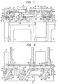
- Figure 1 is a front elevational view of apparatuses for feeding materials to be pressed and pressed materials, which are used to practice the present invention, and Figure 2 a plan view of the same.
- presses 1, 2 and material feeding apparatuses 3, 4 are disposed adjacently to each other, and a series of pressing steps are carried out from the left-hand side of the drawings to the right-hand side thereof.
- An upper metal mould 5 and a lower metal mould 6 are set on the presses 1, 2 (upper and lower metal moulds set on the press 2 are not shown), respectively.
- Upper bearings 7, 8, lower bearings 9, 10, and belt conveyors 11, 12 are provided at front sides of the apparatuses 3, 4.
- Pivots 13, 14, 15, 16, which are turned to left and right alternately at a predetermined angle, and fulcrum shafts 17, 18, 19, which are moved vertically within a predetermined distance, are supported between the upper bearings 7, 8 and lower bearings 9, 10 in the apparatuses 3, 4.
- the pivots 13, 14, 15, 16 have levers 20, 21, 22, 23, respectively, which are formed integrally therewith.
- Carry-in arms 24, 25 are mounted on the fulcrum shafts 17, 19, respectively, and a carry-out arm 26 on the fulcrum shaft 18. These arms 24, 25, 26 are adpated to be turned horizontally around and moved vertically with the fulcrum shafts 17, 18, 19. Namely, the carry-in arms 24, 25 and carry-out arm 26 are moved pivotally and vertically by the fulcrum shafts 17, 18, 19 working as fulcrums for the pivotal movements thereof and provided on the rear surface of the bolster 27.
- the driving systems for moving the carry-in arm 24 and the carry-out arm 26 pivotally or vertically will be described hereinafter with reference to Figures 6 and 7.
- Finger holders 34, 35, 36 are attached to free end portions 28, 29, 30 of the carry-in arms, 24, 25 and carry-out arm 26 via support members 31, 32, 33. Fingers 46, 47, 48, 49, 50, 51, 52, 53, 54, having suction cups 37, 38, 39, 40, 41, 42, 43, 44, 45 as gripper means are fixed to the finger holders 34, 35, 36. Materials to be pressed and pressed materials are shown by two-dot chain lines and designated by reference numerals 55, 56, 57, 58.
- the pressed material 56 is held by the suction cups 40, 41, 42 to be withdrawn from the lower metal mould 6 in the press 1 by the carry-out arm 26 and transferred to the position of the material 7 on the belt conveyor 12.
- the material 55 to be pressed is held by the suction cups 37, 38, 39 to be fed from the belt conveyor 11 to the lower metal mould 6 in the press 1 by the carry-in arm 24.
- the fulcrums for the pivotal movements of the carry-in arms 24, 25 and carry-out arms 26 are set on the rear surface of the bolster 27.
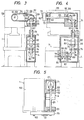
- Figure 3 is a front elevational view in section of a power transmission mechanism for the material feeding apparatus 4 shown in Figures 1 and 2, Figure 4 a side elevational view in section of the same power transmission mechanism, and Figure 5 a top view in section thereof.
- the parts shown in Figures 3, 4 and 5 and identical with those shown in Figure 1 and 1 are designated by the same reference numerals.
- an output shaft 60 which is driven in accordance with an operation of the press 1 by a driving power source for the press 1, extends outward from a front surface of an upper frame 59 of the press 1.
- the output shaft 60 is rotated unitarily with a gear pulley 61.
- An intermediate shaft 65 extending horizontally and rotatably supported on bearings 63, 64, and another intermediate shaft 67 extending downward an rotatably supported on a bearing 66 are housed in a side frame 62 formed integrally with the press 1.
- a gear pulley 68 and bevel gear 69 are fixedly mounted on both end portions of the intermediate shaft 65.
- the gear pulley 68 and a gear pulley 61 mounted on the output shaft 60 are connected together by a timing belt 70, and the bevel gear 69 is connected to a bevel gear 71 fixedly mounted on an upper end portion of the intermediate shaft 67.
- Reference numeral 72 denotes a tightener for the timing belt 70.
- the material feeding apparatus 4 is provided with a vertical cam shaft 75 rotatably supported on bearings 73, 74, and a horizontal cam shaft 78 rotatably supported on bearings 76, 77.
- the vertical cam shaft 75 is connected at its upper end to the intermediate shaft 67 via a coupling 79, and provided at its lower end with a bevel gear 81 mounted fixedly thereon and connected to a bevel gear 80 mounted fixedly on an inner end of the horizontal cam shaft 78.
- Two lever-pivoting cams 82, 83 are formed on the vertical cam shaft 75, and contact at their curved outer circumferential surfaces cam rollers 84, 85 shown by two-dot chain lines.
- the cam roller 84 belongs to the driving system for turning the carry-in arm 24, and the cam roller 85 to the driving system for turning the carry-out arm 26.
- Two lever-lifting-and-lowering-cams 86, 87 are formed on the horizontal cam shaft 78, and contact at their curved outer circumferential surfaces cam rollers 88, 89 shown by two-dot chain lines.
- the cam roller 88 belongs to the driving system for vertically moving the carry-in arm 24, and the cam roller 89 to the driving system for vertically moving the carry-out arm 26.
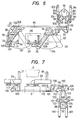
- Figure 6 shows the driving systems for turning the carry-in arm 24 and carry-out arm 26 shown in Figures 1 and 2.
- the parts shown in Figure 6 and identical with those shown in Figures 1 - 5 are designated by the same reference numerals.
- the cam roller 84 contacting the lever-pivoting cam 82 is fixed to one end of a lever 91, which is provided in the material feeding apparatus 4 in such a manner that the lever can be turned around a fulcrum pin 90, and links 92, 93 are connected at one end of each thereof to the other end of the lever 91.
- the link 92 is connected at the other end thereof to one end of the lever 22 supported rotatably on the upper bearing 8 and lower bearing 10 in the material feeding apparatus 4 and formed integrally with the pivot 15.
- the link 93 is connected at the other end thereof to an air cylinder 94.
- the air cylinder 94 is fixed at one end thereof to the material feeding apparatus 4 and adapted to urge the lever 91, which is driven by the lever-pivoting cam 82, in the direction in which the lever 91 is returned to its original position.
- the other end of the lever 22 and one end of the lever 20 supported rotatably on the upper bearing 7 and lower bearing 9 in the material feeding apparatus 3 and formed integrally with the pivot 13 are connected together by a link 95.
- the other end of the lever 20 is connected to the carry-in arm 24 by a link 96.
- the driving system for turning the carry-in arm 24 is formed by the parts connected in the above-described manner.
- a continuous action of the lever 91 which is adapted to be driven by a pivotal movement of the lever-pivoting cam 82 and returned by the air cylinder 94, is transmitted to the carry-in arm 24, so that the carry-in arm 24 is turned to right and left as shown by an arrow 97 around the fulcrum shaft 17 between a position shown by a full line and a position shown by a broken line 24'.
- the cam roller 85 contacting the lever-pivoting cam 83 is fixed to one end of a lever 99, which is provided in the material feeding apparatus 4 in such a manner that the lever 99 can be turned around a fulcrum pin 98, and links 100, 101 are connected at one end of each thereof to the other end of the lever 99.
- the link 100 is connected at the other end thereof to one end of the lever 21 supported rotatably on the upper bearing 8 and lower bearing 10 in the material feeding apparatus 4 and formed integrally with the pivot 14.
- the link 101 is connected at the other end thereof to an air cylinder 102.
- the air cylinder 102 is fixed at one end thereof to the material feeding apparatus 4 and adapted to urge the lever 99, which is driven by the lever-pivoting cam 83, in the direction in which the lever 99 is returned to its original position.
- the other end of the lever 21 and the carry-out arm 26 are connected to each other by a link 103.
- the driving system for turning the carry-out arm 26 is formed by the parts connected in the above-described manner.
- a continuous action of the lever 99 which is adapted to be driven by a pivotal movement of the lever-pivoting cam 83 and returned by the air cylinder 102, is transmitted to the carry-out arm 26, so that the carry-out arm 26 is turned to right and left as shown by an arrow 104 around the fulcrum shaft 18 between a position shown by a full line and a position shown by a broken line 16'.
- a parallel link 106 one end of which is pivotally supported on the lower bearing 9, and the other end of which is connected to an inner end portion 105 of the support member 31, is provided in parallel with the carry-in arm 24. Consequently, a parallelogram 108 shown by a one-dot chain line, one side of which consists of a straight line connecting the fulcrum shaft 17 of the carry-in arm 24 and the axis of a pin 107 by which the support member 31 is connected to the free end portion 28 of the carry-in arm 24, is formed. Accordingly, the finger holder 34 is not turned during a pivotal movement of the carry-in arm 24, so that the material 55 to be pressed can be fed in parallel with both edges of the belt conveyors.
- Reference numeral 109 denotes a parallel link provided in the carry-out arm 26 and working in the same manner as the parallel link 106.
- Figure 7 is a diagram showing driving systems for vertically moving the carry-in arm 24 and carry-out arm 26 shown in Figure 6.
- the parts shown in Figure 7 and idential with those shown in Figures 1 - 6 are designated by the same reference numerals.
- a lever 110 is connected pivotably at its one end to the material feeding apparatus 4 via a fulcrum pin lll, and links 112, 113 at one end of each thereof to the other end of the lever 110.
- the cam roller 88 contacting the lever-lifting-and-lowering-cam 86 is fixed to a substantially intermediate portion of the lever 110.
- the other end of the link l12 is connected to one end of a lever 115, which is supported pivotably on the lower bearing 10 in the material feeding apparatus 4 via a fulcrum pin 114, and the other end of the link l13 to an air cylinder 116.
- the air cylinder 116 is fixed at its one end to the apparatus 4 and adapted to urge the lever 110, which is driven by the lever-lifting-and-lowering-cam 86, in the direction in which the lever 110 is returned to its original position.
- the other end of the lever 118 is connected to a connecting portion 120 formed at a lower end of the fulcrum shaft 17, which is supported on the upper bearing 7 and lower bearing 9 in the apparatus 3 and adapted to be moved unitarily with the carry-in arm 24 in the vertical direction.
- the driving system for vertically moving the carry-in arm 24 is formed by the parts connected together in the above-described manner.
- a continuous action of the lever 110 driven by a pivotal movement of the lever-lifting-and-lowering-cam 86 and returned by the air cylinder 116 is transmitted to the carry-in arm 24, so that the carry-in arm 24 is moved vertically.
- the driving system for vertically moving the carry-out arm 26 will now be described.
- a lever 121 is fixed pivotably at its one end to the material feeding apparatus 4 via a fulcrum pin 122, and links 123, 124 are connected at one end of each thereof to the other end of the lever 121.
- the cam roller 89 contacting the lever-lifting-and-lowering-cam 87 is fixed to a substantially intermediate portion of the lever 121. Since the cam roller 89 is positioned on the same axis as the cam roller 88, it is not shown in the drawing.
- the other end of the link 123 is connected to one end of a lever 126, which is supported pivotably on the lower bearing 10 in the material feeding apparatus 4 via a fulcrum pin 125, and the other end of the link 124 to an air cylinder 127.
- the air cylinder 127 is fixed at one end thereof to the apparatus 4 and adapted to urge the lever 121, which is driven by the lever-lifting-and-lowering-cam 87, in the direction in which the lever 121 is returned to its original position.
- the other end of the lever 129 is connected to a connecting portion 131 formed at a lower end of the fulcrum shaft 18, which is supported on the upper bearing 8 and lower bearing 10 in the apparatus 4 in such a manner that the fulcrum shaft 18 is moved unitarily with the carry-out arm 26 in the vertical direction.
- the driving system for vertically moving the carry-out arm 26 is formed by the parts connected together in the above-described manner.
- a continuous action of the lever 121 which is driven by a pivotal movement of the lever-lifting-and-lowering-cam 87 and returned to its original position by the air cylinder 127, is transmitted to the carry-out arm 26, so that the carry-out arm 26 is moved vertically.
- the carry-out arm 24 and carry-in arm 26 are moved pivotally in the horizontal direction and linearly in the vertical direction, respectively, in accordance with the operations of the lever-pivoting cams 82, 83 and lever-lifting-and-lowering-cams 86, 87, which are performed by the above-described driving systems.
- the material 55 to be pressed which is held by the suction cups 37, 38, 39, is fed to the lower metal mould 6, and the pressed material 56 held by the suction cups 40, 41, 42 is withdrawn therefrom.
- the material 57 is fed to right by the belt conveyor 12, and the material 58 held by the suction cups 43, 44, 45 is fed from the belt conveyor 12 to the press 2 by the carry-in arm 25, which is actuated by" the driving system provided in the material feeding apparatus (not shown) in the press 2.
- the suction cups 40, 41, 42 on the carry-out arm 26 are moved pivotally from a low position close to the pressed material 56 on the lower metal mould 6 to a dead point (position shown by a full line in Figure 6) of pivotal movement of the carry-out arm 26 on the carry-out action starting side thereof, i.e. in the direction of an arrow 133.
- the suction cups 37, 38, 39 on the carry-in arm 24 are set as shown in Figure 8
- the suction cups 37, 38, 39 and fingers 46, 47, 48 do not cross a zone of movement of the upper metal mould 5, and the material 55 to be pressed can be fed onto the lower metal mould 6 along the shortest path to the mentioned zone.
- the suction cups 40, 41, 42 on the carry-out arm 26 are set as shown in Figure 9
- the suction cups 40, 41, 42 and fingers 49, 50, 51 do not cross a zone of movement of the upper mould 5, and the pressed material on the lower metal mould 6 can be held by these cups 40, 41, 42 entering the zone of movement of the upper metal mould 5 along the shortest path thereto.
- a carry-out action of the carry-out arm 26 turned to the dead point (position shown by a broken line in Figure 6) of pivotal movement thereof on the carry-out action terminating side thereof is complete, and the pressed material 56 held by the suction cups 40, 41, 42 is carried onto the belt conveyor 12 to be sent to a subsequent stage.
- the suction cups 37, 38, 39, by which the positioning of the material 55 has been completed, are turned by the carry-in arm 24 from a low return position in the direction of an arrow 139 to be escaped to a position outside of a zone of downward movement of the upper metal mould 5.
- suction cups 37, 38, 39 and fingers 46, 47, 48 are set in the positions mentioned with reference to Figure 8, they can be moved instantly to positions out of the zone of movement of the upper metal mould 5.
- the upper metal mould 5 continues to be moved downward as shown by an arrow 140 to press the material 55.
- the pressed material 56 can be held in the shortest time to be sent out, and the finger holder 34 with the suction cups 37, 38, 39, which are provided on the carry-in arm 24 used to feed ther material 55 to be pressed onto the lower metal mould, can be escaped to positions outside of a zone of movement of the upper metal mould 5.
- the carry-in arms 24, 25 and carry-out arms 26 are designed so as to be turned or vertically moved by driving systems mechanically connected thereto. These arms 24, 25, 26 may be operated by hydraulic driving systems or electric driving systems using servomotors.
- the vacuum suction cups 37, 38, 39, 40, 41, 42, 43, 44, 45 are used as gripper means, which can be substituted by electromagnets or means for mechanically holding a material.
Landscapes
- Engineering & Computer Science (AREA)
- Mechanical Engineering (AREA)
- Press Drives And Press Lines (AREA)
Abstract
Description
- This invention relates to a method of and an apparatus for transporting a workpiece into and out of a workstation, for example feeding a material to be secondarily pressed to a press or withdrawing a secondarily pressed material therefrom, and more particularly to a method of and an apparatus for feeding a material to be pressed to a press of a high speed of operation.
- In a conventional method of feeding materials to be pressed, a pressed material on a metal mould provided in a press is withdrawn therefrom by a carry-out arm, and an untreated material is then placed on the metal mould in the press by a carry-in arm. After the material is pressed, the pressed material is withdrawn again in the same manner. A material to be pressed and a pressed material are fed onto and sent out from a metal mould in the mentioned order to carry out a pressing operation. In order to replace a pressed material on a metal mould with an untreated material to be pressed, the former material is carried out to the outside of a zone in which an upper metal mould is vertically moved, and the latter material is then carried onto the metal mould to be inserted therein.
- Therefore, it takes much time to replace a pressed material with a material to be pressed. In order to carry out such replacement of materials, it is necessary to reduce the speed of operation of a press or temporarily stop an operation thereof. This prevents an increase in the feed rate of materials to be pressed and the productivity of pressed materials.
- To be more specific, when a pressed material on a metal mould is replaced with a material to be pressed, by a carry-out arm and a carry-in arm, each of which has a means for gripping a substantially intermediate portion of a relative material, it is necessary that the movements of three parts, i.e. the gripper means on the carry-out arm, gripper means on the carry-in arm, and vertically displaceable upper metal mould do not obstruct one another in a space above a lower metal mould. Therefore, it is necessary to carry out the replacement of a pressed material with a material to be pressed, after the upper metal mould is lifted sufficiently, and lower the upper metal mould after the replacement of the material is completed with the gripper means on the carry-in arm moved to the outside of a zone in which the upper metal is moved downward.
- Thus, in a conventional apparatus for feeding materials to be pressed, in which much time is required for carrying out the replacement of a material and the transfer of a gripper means to the outside of a zone of movement of an upper metal mould, the speed of operation of a press and the productivity of pressed materials cannot be increased.
- Furthermore, an operation for replacing a metal mould in a press, which is done as necessary, becomes complicated of necessity since the operation is obstructed by carry-in and carry-out means which are provided on a front surface of a bolster. Namely, the conventional apparatus for feeding materials to be pressed cannot adapt itself speedily to the re-arrangement of a production line.
- An object of the present invention is to provide a method of feeding materials to be pressed, which is capable of feeding a unit quantity of material to be pressed, in a greatly shortened period of time and following a high-speed continuous operation of a press.
- Another object of the present invention is to provide an apparatus for feeding materials to be pressed, which is capable of feeding a unit quantity of material to be pressed, in a greatly shortened period of time, following a high-speed continuous operation of a press, and easily carrying out the re-arrangement of a press.
- According to the present invention, a plane in which a carry-out arm is turned is set higher than that in which a carry-in arm is turned, and the carry-in arm is turned to a dead point of pivotal movement on the carry-in action terminating side thereof immediately after the upward movement of the carry-out arm is started in a dead point of pivotal movement on the carry-out action starting side thereof. Thus, the actions of the carry-out arm and the carry-in arm are timed in such a manner that a pressed material sent out by the carry-out arm and an untreated material to be introduced into a mould or die by the carry-in arm are aligned with each other in a vertically spaced relationship in a position above a lower mould or die in a press. Accordingly, the time for feeding a unit quantity of materials to be pressed can be shortened, and the feeding of materials to be pressed can be done in accordance with a high-speed continuous operation of a press.
- In an apparatus according to the present invention, a fulcrum for the pivotal movement of at least one of the carry-in arm and carry-out arm is preferably set on a rear surface of a bolster of a press. Also, positions, to which gripper means provided on the carry-in arm are applied, on a material to be pressed are determined in the circumferential portion thereof which enters a zone of movement of an upper mould in such a position only that is in the vicinity of a dead point of pivotal movement of the carry-in arm on the carry-in action terminating side thereof. Similarly, positions, to which gripper means provided on the carry-out arm are applied, on a pressed material are determined in the circumferencial portions thereof which enters a zone of movement of the upper mould in such a position only that is in the vicinity of a dead point of pivotal movement of the carry-out arm on the carry-out action starting side thereof. Thus, a space suitably used to carry out a metal mould exchanging operation is provided in front of a bolster, and the grippers on the carry-in arm and carry-out arm are adapted to be moved along the shortest possible paths to the outside of a zone of movement of an upper mould. Therefore, the time for feeding a unit quantity of materials to be pressed can be shortened greatly, and the re-arrangement of a press can be done speedily and easily as necessary. In addition, the productivity of pressed materials can be improved.
- Reference is made to the drawings, in which:
- Figure 1 is a front elevational view of examples of material feeding apparatuses used to practice the present invention and presses;
- Figure 2 is a plan view of the presses and material feeding apparatuses shown in Figure 1;
- Figure 3 is a front elevational view in section of a power transmission mechanism for the
material feeding apparatus 4 shown in Figure 1; - Figure 4 is a side elevational view in section of the power transmission mechanism for the
material feeding apparatus 4 shown in Figure 3; - Figure 5 is a top view in section of the power transmission mechanism for the
material feeding apparatus 4 shown in Figure 3; - Figure 6 is a plan view of a driving system for pivotally moving the carry-in
arm 24 and carry-outarm 26 shown in Figures 1 and 2; - Figure 7 is a front elevational view of a driving system for vertically moving the carry-in
arm 24 and carry-outarm 26 shown in Figure 6; and; - Figure 8A, 8B, 9A, 10A, 10B, llA, and 11B are plan views and front elevational views of examples of gripper means used in the present invention, and illustrate the procedure of feeding a material to be pressed and a pressed material.
- Figure 1 is a front elevational view of apparatuses for feeding materials to be pressed and pressed materials, which are used to practice the present invention, and Figure 2 a plan view of the same.
- Referring to Figures 1 and 2, presses 1, 2 and
material feeding apparatuses upper metal mould 5 and alower metal mould 6 are set on thepresses 1, 2 (upper and lower metal moulds set on thepress 2 are not shown), respectively.Upper bearings 7, 8,lower bearings 9, 10, andbelt conveyors apparatuses -
Pivots fulcrum shafts upper bearings 7, 8 andlower bearings 9, 10 in theapparatuses - The
pivots arms 24, 25 are mounted on thefulcrum shafts arm 26 on thefulcrum shaft 18. Thesearms fulcrum shafts arms 24, 25 and carry-outarm 26 are moved pivotally and vertically by thefulcrum shafts bolster 27. The driving systems for moving the carry-inarm 24 and the carry-outarm 26 pivotally or vertically will be described hereinafter with reference to Figures 6 and 7. -
Finger holders free end portions arm 26 viasupport members Fingers suction cups finger holders reference numerals - The
material 58 to be pressed is held by thesuction cups belt conveyor 12 to a lower metal mould (not shown) in thepress 2 by the carry-in arm 25. Thematerial 57 is transferred by thebelt conveyor 12 to the position of thematerial 58. - The pressed
material 56 is held by thesuction cups lower metal mould 6 in thepress 1 by the carry-outarm 26 and transferred to the position of the material 7 on thebelt conveyor 12. Thematerial 55 to be pressed is held by thesuction cups belt conveyor 11 to thelower metal mould 6 in thepress 1 by the carry-inarm 24. In this embodiment, the fulcrums for the pivotal movements of the carry-inarms 24, 25 and carry-outarms 26 are set on the rear surface of thebolster 27. Even when either the carry-inarms 24, 25 or carry-outarm 26 is provided on a front surface of thebolster 27, thepresses material feeding apparatuses - Figure 3 is a front elevational view in section of a power transmission mechanism for the
material feeding apparatus 4 shown in Figures 1 and 2, Figure 4 a side elevational view in section of the same power transmission mechanism, and Figure 5 a top view in section thereof. The parts shown in Figures 3, 4 and 5 and identical with those shown in Figure 1 and 1 are designated by the same reference numerals. - Referring to Figures 3, 4 and 5, an
output shaft 60, which is driven in accordance with an operation of thepress 1 by a driving power source for thepress 1, extends outward from a front surface of anupper frame 59 of thepress 1. Theoutput shaft 60 is rotated unitarily with a gear pulley 61. - An
intermediate shaft 65 extending horizontally and rotatably supported onbearings intermediate shaft 67 extending downward an rotatably supported on abearing 66 are housed in aside frame 62 formed integrally with thepress 1. - A gear pulley 68 and
bevel gear 69 are fixedly mounted on both end portions of theintermediate shaft 65. The gear pulley 68 and a gear pulley 61 mounted on theoutput shaft 60 are connected together by atiming belt 70, and thebevel gear 69 is connected to abevel gear 71 fixedly mounted on an upper end portion of theintermediate shaft 67.Reference numeral 72 denotes a tightener for thetiming belt 70. - The
material feeding apparatus 4 is provided with avertical cam shaft 75 rotatably supported onbearings horizontal cam shaft 78 rotatably supported onbearings - The
vertical cam shaft 75 is connected at its upper end to theintermediate shaft 67 via acoupling 79, and provided at its lower end with abevel gear 81 mounted fixedly thereon and connected to abevel gear 80 mounted fixedly on an inner end of thehorizontal cam shaft 78. - Two lever-
pivoting cams vertical cam shaft 75, and contact at their curved outer circumferentialsurfaces cam rollers cam roller 84 belongs to the driving system for turning the carry-inarm 24, and thecam roller 85 to the driving system for turning the carry-outarm 26. - Two lever-lifting-and-lowering-
cams horizontal cam shaft 78, and contact at their curved outer circumferentialsurfaces cam rollers cam roller 88 belongs to the driving system for vertically moving the carry-inarm 24, and thecam roller 89 to the driving system for vertically moving the carry-outarm 26. - Figure 6 shows the driving systems for turning the carry-in
arm 24 and carry-outarm 26 shown in Figures 1 and 2. The parts shown in Figure 6 and identical with those shown in Figures 1 - 5 are designated by the same reference numerals. - First, the driving system for turning the carry-in
arm 24 will be described. - The
cam roller 84 contacting the lever-pivotingcam 82 is fixed to one end of alever 91, which is provided in thematerial feeding apparatus 4 in such a manner that the lever can be turned around afulcrum pin 90, and links 92, 93 are connected at one end of each thereof to the other end of thelever 91. Thelink 92 is connected at the other end thereof to one end of thelever 22 supported rotatably on theupper bearing 8 andlower bearing 10 in thematerial feeding apparatus 4 and formed integrally with thepivot 15. Thelink 93 is connected at the other end thereof to anair cylinder 94. Theair cylinder 94 is fixed at one end thereof to thematerial feeding apparatus 4 and adapted to urge thelever 91, which is driven by the lever-pivotingcam 82, in the direction in which thelever 91 is returned to its original position. - The other end of the
lever 22 and one end of thelever 20 supported rotatably on the upper bearing 7 and lower bearing 9 in thematerial feeding apparatus 3 and formed integrally with thepivot 13 are connected together by alink 95. The other end of thelever 20 is connected to the carry-inarm 24 by alink 96. - The driving system for turning the carry-in
arm 24 is formed by the parts connected in the above-described manner. A continuous action of thelever 91, which is adapted to be driven by a pivotal movement of the lever-pivotingcam 82 and returned by theair cylinder 94, is transmitted to the carry-inarm 24, so that the carry-inarm 24 is turned to right and left as shown by anarrow 97 around thefulcrum shaft 17 between a position shown by a full line and a position shown by a broken line 24'. - The driving system for turning the carry-out
arm 6 will now be described. - The
cam roller 85 contacting the lever-pivotingcam 83 is fixed to one end of alever 99, which is provided in thematerial feeding apparatus 4 in such a manner that thelever 99 can be turned around afulcrum pin 98, and links 100, 101 are connected at one end of each thereof to the other end of thelever 99. Thelink 100 is connected at the other end thereof to one end of thelever 21 supported rotatably on theupper bearing 8 andlower bearing 10 in thematerial feeding apparatus 4 and formed integrally with thepivot 14. Thelink 101 is connected at the other end thereof to anair cylinder 102. Theair cylinder 102 is fixed at one end thereof to thematerial feeding apparatus 4 and adapted to urge thelever 99, which is driven by the lever-pivotingcam 83, in the direction in which thelever 99 is returned to its original position. The other end of thelever 21 and the carry-outarm 26 are connected to each other by alink 103. - The driving system for turning the carry-out
arm 26 is formed by the parts connected in the above-described manner. A continuous action of thelever 99, which is adapted to be driven by a pivotal movement of the lever-pivotingcam 83 and returned by theair cylinder 102, is transmitted to the carry-outarm 26, so that the carry-outarm 26 is turned to right and left as shown by anarrow 104 around thefulcrum shaft 18 between a position shown by a full line and a position shown by a broken line 16'. - A parallel link 106, one end of which is pivotally supported on the lower bearing 9, and the other end of which is connected to an
inner end portion 105 of thesupport member 31, is provided in parallel with the carry-inarm 24. Consequently, a parallelogram 108 shown by a one-dot chain line, one side of which consists of a straight line connecting thefulcrum shaft 17 of the carry-inarm 24 and the axis of apin 107 by which thesupport member 31 is connected to thefree end portion 28 of the carry-inarm 24, is formed. Accordingly, thefinger holder 34 is not turned during a pivotal movement of the carry-inarm 24, so that the material 55 to be pressed can be fed in parallel with both edges of the belt conveyors.Reference numeral 109 denotes a parallel link provided in the carry-outarm 26 and working in the same manner as the parallel link 106. - Figure 7 is a diagram showing driving systems for vertically moving the carry-in
arm 24 and carry-outarm 26 shown in Figure 6. The parts shown in Figure 7 and idential with those shown in Figures 1 - 6 are designated by the same reference numerals. - First, the driving system for vertically moving the carry-in
arm 24 will be described. - A lever 110 is connected pivotably at its one end to the
material feeding apparatus 4 via a fulcrum pin lll, and links 112, 113 at one end of each thereof to the other end of the lever 110. Thecam roller 88 contacting the lever-lifting-and-lowering-cam 86 is fixed to a substantially intermediate portion of the lever 110. - The other end of the link l12 is connected to one end of a
lever 115, which is supported pivotably on thelower bearing 10 in thematerial feeding apparatus 4 via afulcrum pin 114, and the other end of the link l13 to anair cylinder 116. Theair cylinder 116 is fixed at its one end to theapparatus 4 and adapted to urge the lever 110, which is driven by the lever-lifting-and-lowering-cam 86, in the direction in which the lever 110 is returned to its original position. - The other end of the lever ll5 and one end of a lever 118, which is supported pivotably on the lower bearing 9 in the
material feeding apparatus 3 via apin 117, are connected together via alink 119. The other end of the lever 118 is connected to a connectingportion 120 formed at a lower end of thefulcrum shaft 17, which is supported on the upper bearing 7 and lower bearing 9 in theapparatus 3 and adapted to be moved unitarily with the carry-inarm 24 in the vertical direction. - The driving system for vertically moving the carry-in
arm 24 is formed by the parts connected together in the above-described manner. A continuous action of the lever 110 driven by a pivotal movement of the lever-lifting-and-lowering-cam 86 and returned by theair cylinder 116 is transmitted to the carry-inarm 24, so that the carry-inarm 24 is moved vertically. - The driving system for vertically moving the carry-out
arm 26 will now be described. - A
lever 121 is fixed pivotably at its one end to thematerial feeding apparatus 4 via afulcrum pin 122, and links 123, 124 are connected at one end of each thereof to the other end of thelever 121. Thecam roller 89 contacting the lever-lifting-and-lowering-cam 87 is fixed to a substantially intermediate portion of thelever 121. Since thecam roller 89 is positioned on the same axis as thecam roller 88, it is not shown in the drawing. - The other end of the
link 123 is connected to one end of alever 126, which is supported pivotably on thelower bearing 10 in thematerial feeding apparatus 4 via afulcrum pin 125, and the other end of thelink 124 to anair cylinder 127. Theair cylinder 127 is fixed at one end thereof to theapparatus 4 and adapted to urge thelever 121, which is driven by the lever-lifting-and-lowering-cam 87, in the direction in which thelever 121 is returned to its original position. - The other end of the lever and one end of a
lever 129, which is supported pivotably on thelower bearing 10 in thematerial feeding apparatus 4 via apin 128, are connected together by alink 130. The other end of thelever 129 is connected to a connectingportion 131 formed at a lower end of thefulcrum shaft 18, which is supported on theupper bearing 8 andlower bearing 10 in theapparatus 4 in such a manner that thefulcrum shaft 18 is moved unitarily with the carry-outarm 26 in the vertical direction. - The driving system for vertically moving the carry-out
arm 26 is formed by the parts connected together in the above-described manner. A continuous action of thelever 121, which is driven by a pivotal movement of the lever-lifting-and-lowering-cam 87 and returned to its original position by theair cylinder 127, is transmitted to the carry-outarm 26, so that the carry-outarm 26 is moved vertically. - When the
press 1 is operated, the carry-outarm 24 and carry-inarm 26 are moved pivotally in the horizontal direction and linearly in the vertical direction, respectively, in accordance with the operations of the lever-pivotingcams cams material 55 to be pressed, which is held by thesuction cups lower metal mould 6, and the pressedmaterial 56 held by thesuction cups - The
material 57 is fed to right by thebelt conveyor 12, and the material 58 held by thesuction cups belt conveyor 12 to thepress 2 by the carry-in arm 25, which is actuated by" the driving system provided in the material feeding apparatus (not shown) in thepress 2. - Figures 8, 9, 10 and 11, each of which consists of a plan view (A) and a front elevational view (B), show examples of gripper means used in the present invention and the order of material feeding operations.
- The order of material feeding operations will now be described with reference to Figures 1 - 7 as well.
- Referring to Figure 8, when the pressing work for the
material 56 is completed by thepress 1, theupper metal mould 5 starts being lifted in the direction of anarrow 132. The material 55 to be pressed, which is on thebelt conveyor 11, is held by thesuction cups arm 24 in a dead point (position shown by a full line in Figure 6) of pivotal movement of the carry-inarm 24 on the carry-in action starting side thereof. The material 55 to be pressed is held at the two front portions of an outer circumferential section thereof which are the closest to thefinger holder 34 and at one left rear portion of the outer circumferential section thereof. Accordingly, thefinger 46 in use, which has thesuction cup 37, is made long. - The suction cups 40, 41, 42 on the carry-out
arm 26 are moved pivotally from a low position close to the pressedmaterial 56 on thelower metal mould 6 to a dead point (position shown by a full line in Figure 6) of pivotal movement of the carry-outarm 26 on the carry-out action starting side thereof, i.e. in the direction of anarrow 133. - Referring to Figure 9, when the
upper metal mould 5 in thepress 1 is moved to an upper dead point with the pressedmaterial 56, which is held by thesuction cups arm 26, moved upward as shown by an arrow 134, thematerial 55 to be pressed, which is held by thesuction cups arm 24, is moved pivotally at once from a position lower than the pressedmaterial 56 in the direction of anarrow 135 to be fed onto thelower metal mould 6. The pressedmaterial 56 to be sent out by the carry-outarm 26 is held at the two front portions of an outer circumferential section thereof which are the closest to thefinger holder 35 and at one right rear portion of an outer circumferential section thereof. Accordingly, thefinger 51 in use, which has thesuction cup 42, is made long in the same way as thefinger 46 on the carry-inarm 24. - Since the positions of the
suction cups arm 24 are set as shown in Figure 8 thesuction cups fingers upper metal mould 5, and the material 55 to be pressed can be fed onto thelower metal mould 6 along the shortest path to the mentioned zone. Since the positions of thesuction cups arm 26 are set as shown in Figure 9, thesuction cups fingers upper mould 5, and the pressed material on thelower metal mould 6 can be held by thesecups upper metal mould 5 along the shortest path thereto. - Referring to Figure 10, when the
upper metal mould 5 starts being lowered as shown by an arrow 136, for carrying out a subsequent operation, the pressedmaterial 56 held by thesuction cups arrow 137, to be taken out in a position which is out of a zone of downward movement of theupper metal mould 5. When the carry-inarm 24 is turned to a dead point (position shown by a broken line in Figure 6) of pivotal movement thereof on the carry-in action terminating side thereof, thematerial 55 to be pressed is fed onto thelower metal mould 6. Thematerial 55 is then lowered in the direction of an arrow 138 in accordance with a slight downward movement of the carry-inarm 24 to be placed on a pressing position on thelower metal mould 6. - Referring to Figure 11, a carry-out action of the carry-out
arm 26 turned to the dead point (position shown by a broken line in Figure 6) of pivotal movement thereof on the carry-out action terminating side thereof is complete, and the pressedmaterial 56 held by thesuction cups belt conveyor 12 to be sent to a subsequent stage. The suction cups 37, 38, 39, by which the positioning of thematerial 55 has been completed, are turned by the carry-inarm 24 from a low return position in the direction of anarrow 139 to be escaped to a position outside of a zone of downward movement of theupper metal mould 5. Since thesuction cups fingers upper metal mould 5. Theupper metal mould 5 continues to be moved downward as shown by anarrow 140 to press thematerial 55. - The action described above with reference to Figures 8 - 11, which constitutes one cycle of press work, is repeated to press materials in order. The material 55 to be pressed is fed onto the
lower metal mould 6 immediately after the pressedmaterial 56 is lifted slightly therefrom. Accordingly, thematerials upper metal mould 5. Moreover, thematerial 56 can be replaced by thematerial 55 within one stroke of upward or downward movement of theupper metal mould 5; the speed of a downward movement of theupper metal mould 5 need not be reduced, nor does themould 5 need to be stopped temporarily, for carrying out the replacement of thesematerials material 56 can be held in the shortest time to be sent out, and thefinger holder 34 with thesuction cups arm 24 used to feedther material 55 to be pressed onto the lower metal mould, can be escaped to positions outside of a zone of movement of theupper metal mould 5. - In the embodiment shown in Figures 1 - 7, the carry-in
arms 24, 25 and carry-outarms 26 are designed so as to be turned or vertically moved by driving systems mechanically connected thereto. Thesearms - ' The
vacuum suction cups
Claims (8)
Applications Claiming Priority (4)
| Application Number | Priority Date | Filing Date | Title |
|---|---|---|---|
| JP43131/83 | 1983-03-17 | ||
| JP58043130A JPS59169633A (en) | 1983-03-17 | 1983-03-17 | Method of feeding of material for pressing |
| JP43130/83 | 1983-03-17 | ||
| JP58043131A JPS59169634A (en) | 1983-03-17 | 1983-03-17 | Feeding device of material for pressing |
Publications (3)
| Publication Number | Publication Date |
|---|---|
| EP0123398A2 true EP0123398A2 (en) | 1984-10-31 |
| EP0123398A3 EP0123398A3 (en) | 1986-05-14 |
| EP0123398B1 EP0123398B1 (en) | 1989-05-17 |
Family
ID=26382879
Family Applications (1)
| Application Number | Title | Priority Date | Filing Date |
|---|---|---|---|
| EP84301662A Expired EP0123398B1 (en) | 1983-03-17 | 1984-03-13 | Method of and apparatus for transporting workpieces into and out of a press or other workstation |
Country Status (3)
| Country | Link |
|---|---|
| US (1) | US4566306A (en) |
| EP (1) | EP0123398B1 (en) |
| DE (1) | DE3478203D1 (en) |
Cited By (1)
| Publication number | Priority date | Publication date | Assignee | Title |
|---|---|---|---|---|
| CN111375671A (en) * | 2020-03-11 | 2020-07-07 | 浙江金工机械设备科技有限公司 | Composite blanking die device capable of realizing continuous stamping production |
Families Citing this family (4)
| Publication number | Priority date | Publication date | Assignee | Title |
|---|---|---|---|---|
| US4974439A (en) * | 1988-07-01 | 1990-12-04 | Saunders William T | Controlled transfer of sheet metal can bodies in can body line |
| US5006028A (en) * | 1990-05-18 | 1991-04-09 | Jackson Donald T | Cam lift and carry parts transfer apparatus |
| DE4117102A1 (en) * | 1991-05-25 | 1992-11-26 | Schuler Gmbh L | PRESS WITH DRAWING DEVICE |
| US5632181A (en) * | 1995-02-23 | 1997-05-27 | Verson, A Division Of Allied Products Corporation | System and method for transferring a work piece in a multi-station press |
Family Cites Families (19)
| Publication number | Priority date | Publication date | Assignee | Title |
|---|---|---|---|---|
| US2312355A (en) * | 1938-07-21 | 1943-03-02 | Ingersoll Milling Machine Co | Method of scalping billets |
| DE900563C (en) * | 1943-01-05 | 1953-12-28 | Sachsenwerk Licht & Kraft Ag | Device for the automatic insertion and removal of individual parts in machine tools for non-cutting shaping |
| US2711817A (en) * | 1954-06-02 | 1955-06-28 | Llewellyn A Hautau | Mechanical loader and unloader for production machines |
| US3282079A (en) * | 1963-05-16 | 1966-11-01 | Ajax Mfg Co | Work handling mechanism for forging presses and the like |
| US3199443A (en) * | 1964-03-26 | 1965-08-10 | Danly Mach Specialties Inc | Automatic transfer mechanism for press line |
| US3948162A (en) * | 1971-03-05 | 1976-04-06 | Aida Engineering Limited | Press line system |
| IT978844B (en) * | 1972-02-07 | 1974-09-20 | Langenstein & Schemann Ag | FORGING MACHINE WITH MANIPULATOR DEVICE |
| US3834213A (en) * | 1973-02-12 | 1974-09-10 | Hanzler Mfg Corp | Workpiece translation mechanism for transfer die press |
| FR2223104A1 (en) * | 1973-03-29 | 1974-10-25 | Sepro Etud Rech Produits | Pressing machine with two-part tools - with means for holding workpiece to one part and blank to other |
| DE2411299C3 (en) * | 1974-03-09 | 1979-07-05 | G. Siempelkamp Gmbh & Co, 4150 Krefeld | Machine for manipulating panels, especially for destacking chipboard |
| DE2438960C3 (en) * | 1974-08-14 | 1978-08-03 | G. Siempelkamp Gmbh & Co, 4150 Krefeld | Device for stacking and unstacking plate-shaped! Good |
| US3937056A (en) * | 1975-03-25 | 1976-02-10 | Henzler Mfg. Corporation | Workpiece translation mechanism for transfer die press |
| US4056198A (en) * | 1976-03-29 | 1977-11-01 | Danly Machine Corporation | Transfer and turnover mechanism for use with power press or the like |
| FR2441442A2 (en) * | 1978-11-15 | 1980-06-13 | Weingarten Ag Maschf | DEVICE FOR INTERCOVERING BETWEEN TWO PRESSES, PARTICULARLY FOR WORKPIECES WITH A LARGE FLAT SURFACE |
| JPS55106546U (en) * | 1979-01-22 | 1980-07-25 | ||
| US4411587A (en) * | 1980-07-30 | 1983-10-25 | Nagoya Kiko Kabushiki Kaisha | Loading apparatus |
| SE433722B (en) * | 1981-07-10 | 1984-06-12 | Asea Ab | PLATPRESSER HANDLING EQUIPMENT |
| JPS5874227A (en) * | 1981-10-27 | 1983-05-04 | Orii Jidoki Seisakusho:Kk | Automatic feed device of workpiece |
| JPS58176030A (en) * | 1982-04-10 | 1983-10-15 | Nagao Tekkosho:Kk | Press machine having built-in robot |
-
1984
- 1984-03-08 US US06/587,535 patent/US4566306A/en not_active Expired - Fee Related
- 1984-03-13 EP EP84301662A patent/EP0123398B1/en not_active Expired
- 1984-03-13 DE DE8484301662T patent/DE3478203D1/en not_active Expired
Cited By (1)
| Publication number | Priority date | Publication date | Assignee | Title |
|---|---|---|---|---|
| CN111375671A (en) * | 2020-03-11 | 2020-07-07 | 浙江金工机械设备科技有限公司 | Composite blanking die device capable of realizing continuous stamping production |
Also Published As
| Publication number | Publication date |
|---|---|
| DE3478203D1 (en) | 1989-06-22 |
| EP0123398B1 (en) | 1989-05-17 |
| EP0123398A3 (en) | 1986-05-14 |
| US4566306A (en) | 1986-01-28 |
Similar Documents
| Publication | Publication Date | Title |
|---|---|---|
| US3422657A (en) | Press transfer mechanism | |
| CN104608186A (en) | High-frequency platen die-cutting machine | |
| CN119114737A (en) | A beam-type automated punching machine used for photovoltaic frame processing | |
| US3885680A (en) | Apparatus provided at presses for the lifting and conveying of workpieces | |
| EP0123398B1 (en) | Method of and apparatus for transporting workpieces into and out of a press or other workstation | |
| JPH115133A (en) | Combined goods transport device | |
| US5775163A (en) | Transfer arrangement for multistation presses | |
| CN213256754U (en) | Automatic feeding device of punching machine | |
| JPH0116217B2 (en) | ||
| US3719270A (en) | Workpiece transfer device | |
| JP3651953B2 (en) | Material feeder | |
| US3776342A (en) | Apparatus for transferring articles between moving conveyors | |
| KR0128005B1 (en) | Material transfer device of forging machine | |
| US4407630A (en) | Work feed method in a press | |
| US3881436A (en) | Workpiece transfer mechanism | |
| KR880000614B1 (en) | Supplying method of materials to press | |
| JPS58120478A (en) | Automatic sending apparatus of article to be processed | |
| CN219336707U (en) | Multi-station online carrying and pressing equipment | |
| CN1072045C (en) | Device for automatic conveying of workpieces on a multi-stage forming machine | |
| JPS649093B2 (en) | ||
| JP2002346667A (en) | Method of replacing work holding means of transfer feeder and apparatus for replacing the same | |
| CN121373171A (en) | A stabilizer bar dual-head molding system | |
| CN220536892U (en) | Multiunit double-deck transport transfer device | |
| JP2563868Y2 (en) | Gripping claw lifting device for transfer feeder | |
| CN217964615U (en) | Forging press manipulator |
Legal Events
| Date | Code | Title | Description |
|---|---|---|---|
| PUAI | Public reference made under article 153(3) epc to a published international application that has entered the european phase |
Free format text: ORIGINAL CODE: 0009012 |
|
| AK | Designated contracting states |
Designated state(s): DE FR GB IT |
|
| PUAL | Search report despatched |
Free format text: ORIGINAL CODE: 0009013 |
|
| AK | Designated contracting states |
Kind code of ref document: A3 Designated state(s): DE FR GB IT |
|
| 17P | Request for examination filed |
Effective date: 19860929 |
|
| RAP1 | Party data changed (applicant data changed or rights of an application transferred) |
Owner name: KABUSHIKIGAISHA ORII |
|
| 17Q | First examination report despatched |
Effective date: 19871208 |
|
| GRAA | (expected) grant |
Free format text: ORIGINAL CODE: 0009210 |
|
| AK | Designated contracting states |
Kind code of ref document: B1 Designated state(s): DE FR GB IT |
|
| PG25 | Lapsed in a contracting state [announced via postgrant information from national office to epo] |
Ref country code: FR Free format text: THE PATENT HAS BEEN ANNULLED BY A DECISION OF A NATIONAL AUTHORITY Effective date: 19890517 |
|
| ITF | It: translation for a ep patent filed | ||
| REF | Corresponds to: |
Ref document number: 3478203 Country of ref document: DE Date of ref document: 19890622 |
|
| EN | Fr: translation not filed | ||
| PLBE | No opposition filed within time limit |
Free format text: ORIGINAL CODE: 0009261 |
|
| STAA | Information on the status of an ep patent application or granted ep patent |
Free format text: STATUS: NO OPPOSITION FILED WITHIN TIME LIMIT |
|
| 26N | No opposition filed | ||
| ITTA | It: last paid annual fee | ||
| PGFP | Annual fee paid to national office [announced via postgrant information from national office to epo] |
Ref country code: GB Payment date: 19930302 Year of fee payment: 10 |
|
| PGFP | Annual fee paid to national office [announced via postgrant information from national office to epo] |
Ref country code: DE Payment date: 19930319 Year of fee payment: 10 |
|
| PG25 | Lapsed in a contracting state [announced via postgrant information from national office to epo] |
Ref country code: GB Effective date: 19940313 |
|
| GBPC | Gb: european patent ceased through non-payment of renewal fee |
Effective date: 19940313 |
|
| PG25 | Lapsed in a contracting state [announced via postgrant information from national office to epo] |
Ref country code: DE Effective date: 19941201 |