EP0123358B1 - Combined lock structure for article carrier - Google Patents
Combined lock structure for article carrier Download PDFInfo
- Publication number
- EP0123358B1 EP0123358B1 EP84200548A EP84200548A EP0123358B1 EP 0123358 B1 EP0123358 B1 EP 0123358B1 EP 84200548 A EP84200548 A EP 84200548A EP 84200548 A EP84200548 A EP 84200548A EP 0123358 B1 EP0123358 B1 EP 0123358B1
- Authority
- EP
- European Patent Office
- Prior art keywords
- slits
- relief
- slit
- closure panel
- openings
- Prior art date
- Legal status (The legal status is an assumption and is not a legal conclusion. Google has not performed a legal analysis and makes no representation as to the accuracy of the status listed.)
- Expired
Links
Images

Classifications
-
- B—PERFORMING OPERATIONS; TRANSPORTING
- B65—CONVEYING; PACKING; STORING; HANDLING THIN OR FILAMENTARY MATERIAL
- B65D—CONTAINERS FOR STORAGE OR TRANSPORT OF ARTICLES OR MATERIALS, e.g. BAGS, BARRELS, BOTTLES, BOXES, CANS, CARTONS, CRATES, DRUMS, JARS, TANKS, HOPPERS, FORWARDING CONTAINERS; ACCESSORIES, CLOSURES, OR FITTINGS THEREFOR; PACKAGING ELEMENTS; PACKAGES
- B65D71/00—Bundles of articles held together by packaging elements for convenience of storage or transport, e.g. portable segregating carrier for plural receptacles such as beer cans or pop bottles; Bales of material
- B65D71/06—Packaging elements holding or encircling completely or almost completely the bundle of articles, e.g. wrappers
- B65D71/12—Packaging elements holding or encircling completely or almost completely the bundle of articles, e.g. wrappers the packaging elements, e.g. wrappers being formed by folding a single blank
- B65D71/14—Packaging elements holding or encircling completely or almost completely the bundle of articles, e.g. wrappers the packaging elements, e.g. wrappers being formed by folding a single blank having a tubular shape, e.g. tubular wrappers without end walls
- B65D71/16—Packaging elements holding or encircling completely or almost completely the bundle of articles, e.g. wrappers the packaging elements, e.g. wrappers being formed by folding a single blank having a tubular shape, e.g. tubular wrappers without end walls with article-locating elements
-
- B—PERFORMING OPERATIONS; TRANSPORTING
- B65—CONVEYING; PACKING; STORING; HANDLING THIN OR FILAMENTARY MATERIAL
- B65D—CONTAINERS FOR STORAGE OR TRANSPORT OF ARTICLES OR MATERIALS, e.g. BAGS, BARRELS, BOTTLES, BOXES, CANS, CARTONS, CRATES, DRUMS, JARS, TANKS, HOPPERS, FORWARDING CONTAINERS; ACCESSORIES, CLOSURES, OR FITTINGS THEREFOR; PACKAGING ELEMENTS; PACKAGES
- B65D2571/00—Bundles of articles held together by packaging elements for convenience of storage or transport, e.g. portable segregating carrier for plural receptacles such as beer cans, pop bottles; Bales of material
- B65D2571/00123—Bundling wrappers or trays
- B65D2571/00129—Wrapper locking means
- B65D2571/00135—Wrapper locking means integral with the wrapper
- B65D2571/00154—Wrapper locking means integral with the wrapper interlocked
- B65D2571/0016—Wrapper locking means integral with the wrapper interlocked by tabs protruding from one end and co-operating with openings at the other end
-
- B—PERFORMING OPERATIONS; TRANSPORTING
- B65—CONVEYING; PACKING; STORING; HANDLING THIN OR FILAMENTARY MATERIAL
- B65D—CONTAINERS FOR STORAGE OR TRANSPORT OF ARTICLES OR MATERIALS, e.g. BAGS, BARRELS, BOTTLES, BOXES, CANS, CARTONS, CRATES, DRUMS, JARS, TANKS, HOPPERS, FORWARDING CONTAINERS; ACCESSORIES, CLOSURES, OR FITTINGS THEREFOR; PACKAGING ELEMENTS; PACKAGES
- B65D2571/00—Bundles of articles held together by packaging elements for convenience of storage or transport, e.g. portable segregating carrier for plural receptacles such as beer cans, pop bottles; Bales of material
- B65D2571/00123—Bundling wrappers or trays
- B65D2571/00129—Wrapper locking means
- B65D2571/00135—Wrapper locking means integral with the wrapper
- B65D2571/00154—Wrapper locking means integral with the wrapper interlocked
- B65D2571/00172—Wrapper locking means integral with the wrapper interlocked by tabs cut within one end and facing towards the other end when blank is unfolded, and co-operting with openings at the other end
-
- B—PERFORMING OPERATIONS; TRANSPORTING
- B65—CONVEYING; PACKING; STORING; HANDLING THIN OR FILAMENTARY MATERIAL
- B65D—CONTAINERS FOR STORAGE OR TRANSPORT OF ARTICLES OR MATERIALS, e.g. BAGS, BARRELS, BOTTLES, BOXES, CANS, CARTONS, CRATES, DRUMS, JARS, TANKS, HOPPERS, FORWARDING CONTAINERS; ACCESSORIES, CLOSURES, OR FITTINGS THEREFOR; PACKAGING ELEMENTS; PACKAGES
- B65D2571/00—Bundles of articles held together by packaging elements for convenience of storage or transport, e.g. portable segregating carrier for plural receptacles such as beer cans, pop bottles; Bales of material
- B65D2571/00123—Bundling wrappers or trays
- B65D2571/00246—Locating elements for the contents
- B65D2571/00253—Locating elements for the contents integral with the wrapper
- B65D2571/00277—Slits or openings formed along a fold line
-
- B—PERFORMING OPERATIONS; TRANSPORTING
- B65—CONVEYING; PACKING; STORING; HANDLING THIN OR FILAMENTARY MATERIAL
- B65D—CONTAINERS FOR STORAGE OR TRANSPORT OF ARTICLES OR MATERIALS, e.g. BAGS, BARRELS, BOTTLES, BOXES, CANS, CARTONS, CRATES, DRUMS, JARS, TANKS, HOPPERS, FORWARDING CONTAINERS; ACCESSORIES, CLOSURES, OR FITTINGS THEREFOR; PACKAGING ELEMENTS; PACKAGES
- B65D2571/00—Bundles of articles held together by packaging elements for convenience of storage or transport, e.g. portable segregating carrier for plural receptacles such as beer cans, pop bottles; Bales of material
- B65D2571/00123—Bundling wrappers or trays
- B65D2571/00246—Locating elements for the contents
- B65D2571/00253—Locating elements for the contents integral with the wrapper
- B65D2571/0029—Openings in top or bottom walls
-
- B—PERFORMING OPERATIONS; TRANSPORTING
- B65—CONVEYING; PACKING; STORING; HANDLING THIN OR FILAMENTARY MATERIAL
- B65D—CONTAINERS FOR STORAGE OR TRANSPORT OF ARTICLES OR MATERIALS, e.g. BAGS, BARRELS, BOTTLES, BOXES, CANS, CARTONS, CRATES, DRUMS, JARS, TANKS, HOPPERS, FORWARDING CONTAINERS; ACCESSORIES, CLOSURES, OR FITTINGS THEREFOR; PACKAGING ELEMENTS; PACKAGES
- B65D2571/00—Bundles of articles held together by packaging elements for convenience of storage or transport, e.g. portable segregating carrier for plural receptacles such as beer cans, pop bottles; Bales of material
- B65D2571/00123—Bundling wrappers or trays
- B65D2571/00648—Elements used to form the wrapper
- B65D2571/00654—Blanks
- B65D2571/0066—Blanks formed from one single sheet
-
- B—PERFORMING OPERATIONS; TRANSPORTING
- B65—CONVEYING; PACKING; STORING; HANDLING THIN OR FILAMENTARY MATERIAL
- B65D—CONTAINERS FOR STORAGE OR TRANSPORT OF ARTICLES OR MATERIALS, e.g. BAGS, BARRELS, BOTTLES, BOXES, CANS, CARTONS, CRATES, DRUMS, JARS, TANKS, HOPPERS, FORWARDING CONTAINERS; ACCESSORIES, CLOSURES, OR FITTINGS THEREFOR; PACKAGING ELEMENTS; PACKAGES
- B65D2571/00—Bundles of articles held together by packaging elements for convenience of storage or transport, e.g. portable segregating carrier for plural receptacles such as beer cans, pop bottles; Bales of material
- B65D2571/00123—Bundling wrappers or trays
- B65D2571/00709—Shape of the formed wrapper, i.e. shape of each formed element if the wrapper is made from more than one element
- B65D2571/00716—Shape of the formed wrapper, i.e. shape of each formed element if the wrapper is made from more than one element tubular without end walls
Definitions
- This invention relates to an article carrier of the wraparound type and, more particularly, to a carrier for packaging a plurality of articles in at least one row having an improved thread-and- punch type lock for interlocking overlapping panels of the carrier.
- U.S. Patent 4 200 220 to Ganz is directed to an article carrier of the wraparound type in which the bottom panels of an elongated blank are secured in overlapping relation. Tongues on one of the bottom panels are threaded into corresponding transversely elongated slits in the other of the bottom panels, but this is done only after doubling over each bottom panel with a fold of 180°.
- Each of the tongues has a tab longitudinally aligned therewith for disposition in a cooperating elongated slit on the opposite bottom panel. However, when locked in place, there is no edge-to-edge engagement for the best locking performance. Instead the tab lies in a plane substantially perpendicular to the plane in which the tongue lies.
- This carton requires complicated machinery to perform the doubling over folds and threading of the tongue and tab. Also, the tab which extends vertically into the interior of the carton is susceptible to damage by the articles within the carrier and, in a damaged state, likely to slip back through the receiving slit. The doubling feature greatly increases the cost of the carrier due to the increase in paperboard required.
- U.S. Patents 2 990 997 and 3 223 308 to Weiss are both also directed to an article carrier of the wraparound type of sheet material for packaging of a plurality articles in at least one row including:
- said second closure panel includes closure panel material between said first and second openings, said material forming a protector strap, one protector strap being in longitudinal alignment with each locking unit; each of said second openings having one of said tongues threadable therein so that said tongue overlies said second closure panel when said first and second closure panels are in overlapping relation, each of said first openings having one of said locking tabs punchable therein so that said tab overlies said second closure panel and provides edge-to-edge engagement with said first opening.
- said first and second openings are elongated slits such that the protector strap extends the full width between both slits and overlies the locking tab along the interior of said article carrier to retain said locking tab in edge-to-edge engagement and provide extra strength.
- the carrier of the present invention is an improvement over the prior art disclosed in U.S. Patent 2,990,997 in that it insures the required relief for ease of engaging the lock units by providing relief slits extending at different angles from said first and second slits.
- Another object of the invention is to provide a wraparound carrier which minimizes paperboard requirement and thus costs less to manufacture.
- Another object of this invention is to provide a lock structure in a wraparound carrier including spaced locking slits to receive and retain a locking unit with protection against inadvertent release.
- Still another object of this invention is to provide a lock in a carrier having specially formed slits for the purpose indicated to provide improved lock performance and additional security.
- Still another object of this invention is to provide a wraparound carrier with an improved lock as described that is easy to erect on existing highspeed equipment.
- an article carrier of the wraparound type disclosed in US-A-2 990 997 is characterised by the features specified in the characterising portion of claim 1.
- the tongue and locking tab extending in opposing directions and engaging the locating edge and the locking edge of the two slits, respectively, are within the same plane and thus provide the carrier with secure edge-to-edge engagement between the closure panels. Since the tab does not extend vertically up into the carrier but instead is positively held down by the protector strap, it is protected from being inadvertently damaged and dislodged by articles therein. Also, the positive edge-to-edge engagement prevents either the threaded tongue or the punched-in-tab from slipping through its slit. Improved locking retention that in turn improves carton reliability is the favorable result obtained.
- the invention employs two, substantially parallel, transversely elongated slits, and a protector strap in between, the need to strip the trim from a hole or aperture, as often required in the prior art is avoided.
- This feature coupled with reduced paperboard required with respect to some designs, substantially reduces the cost incurred by the manufacturer.
- the present invention provides convenient mechanical threading and punching for easy adaptation to high speed, state of the art automation techniques and machines.
- the protector strap which overlies the tab along the interior of the carrier to hold the tab in locked engagement also increases the strength of the panel in the lock area, whereas before, a relatively wide aperture (absence of material) existed, the protector strap connected by bridges at each end spans the lock area.
- This strap provides an article carrier of increased strength over those in the prior art even after exposure to refrigerated conditions wherein the paper absorbs moisture and loses stiffness.
- the bottles 11 are arranged in two rows, but there can be only a single row or more than two rows.
- the article carrier 10 is formed from an elongated blank 12 (see Figure 1) of a suitable foldable sheet material such as paperboard, for example.
- the elongated blank 12 has a single top panel 14 with circular apertures 13 cut therein to accommodate the necks of the bottles 11.
- Side panels 16 are articulated or hingedly joined to opposite sides of the top panel 14 along a pair of top fold lines 15.
- the side panels 16 are designed to be substantially vertical in the completed article carrier 10, as shown in Figure 2.
- a bottom closure panel 21 is articulated or hingedly joined to one of the side panels 16 along a fold line 22 (see top of Figure 2).
- Another bottom or closure panel 23 is articulated or hingedly joined to the other of the side panels 16 by fold line 24.
- the bottom panel 21 has a plurality of transversely spaced lock units each including a tongue 25 (three shown in Figure 1) with the number of tongues 25 preferably being equal to the number of bottles 11 (see Figure 2) in each of the rows.
- the tongues 25 are spaced from each other by recessed edge portions 26 between the tongues.
- the outer ends of the edge along the panel 21 adjacent the end tongues 25 are formed by an edge extension 30 and connect to longitudinal side edges 31 and 32 of the elongated blank 12.
- the bottom panel 21 thus has its terminal edge defined by the edges of the tongues 25, the recessed edge portions 26 and the connecting edge extensions 30.
- the bottom panel 23 has a plurality of pairs of adjacent, substantially parallel, transversely elongated slits for receiving the corresponding locking units when the closure panels are in proper overlapping relation.
- First transversely elongated slits 33 are formed adjacent the terminal edge 34 of the bottom panel 23, between the terminal edge 34 and second transversely elongated slits 35.
- the bottom panel material disposed between the first slits 33 and second slits 35 forms a protector strap 38.
- the first slit 33 includes relief extensions 33a at each end thereof, and these extensions 33a extend toward said adjacent second slit35 at an angle ofsubstantially 135° from the slit 33.
- the second slit 35 includes relief slits 35a at each end thereof, and these relief slits 35a extend toward said adjacent first slit 33 at an angle of substantially 90° from said second slit 35; the corner is rounded to minimize the tendency to tear the paperboard.
- the relief extensions 33a and relief slits 35a further define the bridges at the ends of the protector strap 38.
- the bridges (see Figures 1 and 4) have a length substantially equal to the combined length of relief extensions 33a and slits 35a to insure maximum strength while at the same time providing the required relief for ease of engaging the lock units.
- Each of the tongues 25 is threadable into one of the transversely elongated slits 35 when the bottom or closure 21 and 23 are in overlapping relation.
- Each tongue 25 overlies the inner transverse edge of the corresponding slit 35 so as to have a relatively large area of overlapping contact ( Figure 4A). As can be seen, the edge of the slit 35 forms a locating edge for the locking unit.
- the bottom panel 21 has a set of locking tabs, designated by the reference numeral 39; a single locking tab being longitudinally aligned with each of the tongues 25.
- the locking tabs 39 are formed through slitting the bottom panel 21 and may be bifurcated, as shown in the preferred embodiment.
- the locking tabs 39 and the tongues 25 together form the locking unit, generally designated by the reference numeral 40 ( Figures 1 and 3).
- the locking tab 39 is then punched (from below) through the transversely elongated slit 33 so that the locking tab 39 directly overlies closure panel 23 thereby providing edge to edge engagement with the transverse edge (see Figure 4B). Further, the protector strap 38 overlies the tab 39 to hold the tab in locked engagement while providing additional strength and support to the carrier 10.
- Figure 4C A fragmentary view of the fully threaded article carrier 10 from below is shown in Figure 4C.
- the elongated blank 12 is first placed over the necks of the bottles 11.
- the side panels 16 are folded down the sides.
- the bottom panels 21 and 23 are folded under the bottoms of the botles 11.
- the tongues 25 are threaded into the transversely elongated slits 35 and the locking tabs 39 are punched into the longitudinally aligned transversely elongated slits33 by forcing with punching wheels (not shown) past the transverse edge of the slits 33.
- the locking arrangement of the present invention enables a relatively large edge to edge locating and locking engagement in a transverse direction.
- a firm, secure and protected locking engagement safe against inadvertent release is provided.
- the improved performance is obtained without any increase in paperboard in the blank over that used in the original Pierce carrier shown in the previous Certipak patent cited above, and considerably less than that used in later patents seeking to improve the strength.
- the lock structure of the present invention also provides convenient mechanical threading and punching for adaptation with state of the art machines and improved automation techniques.
- the blank could be provided with slits having different shapes and configurations.
- the edges of the blank may not necessarily be as shown but could include other shapes and separate angled portions.
Description
- This invention relates to an article carrier of the wraparound type and, more particularly, to a carrier for packaging a plurality of articles in at least one row having an improved thread-and- punch type lock for interlocking overlapping panels of the carrier.
- U.S. Patent 4 200 220 to Ganz is directed to an article carrier of the wraparound type in which the bottom panels of an elongated blank are secured in overlapping relation. Tongues on one of the bottom panels are threaded into corresponding transversely elongated slits in the other of the bottom panels, but this is done only after doubling over each bottom panel with a fold of 180°. Each of the tongues has a tab longitudinally aligned therewith for disposition in a cooperating elongated slit on the opposite bottom panel. However, when locked in place, there is no edge-to-edge engagement for the best locking performance. Instead the tab lies in a plane substantially perpendicular to the plane in which the tongue lies.
- This carton requires complicated machinery to perform the doubling over folds and threading of the tongue and tab. Also, the tab which extends vertically into the interior of the carton is susceptible to damage by the articles within the carrier and, in a damaged state, likely to slip back through the receiving slit. The doubling feature greatly increases the cost of the carrier due to the increase in paperboard required.
- U.S. Patents 2 990 997 and 3 223 308 to Weiss are both also directed to an article carrier of the wraparound type of sheet material for packaging of a plurality articles in at least one row including:
- (a) an elongated blank having fold lines to form a top panel, two side panels and first and second bottom, closure panels designed to overlap when applied to the articles to be packaged;
- (b) said first closure panel including a plurality of locking units, each locking unit having a tonque along the transverse, terminal edge of said first closure panel and a locking tab in longitudinal alignment therewith;
- (c) said second closure panel including a plurality of first and second transversely elongated openings, said first openings being adjacent and substantially parallel to said second openings and lying parallel to and between said second openings and the transverse, terminal edge of said second closure panel, said transverse, terminal edge of said second closure panel being opposite to said transverse, terminal edge of said first closure panel on said blank,
- and wherein said second closure panel includes closure panel material between said first and second openings, said material forming a protector strap, one protector strap being in longitudinal alignment with each locking unit; each of said second openings having one of said tongues threadable therein so that said tongue overlies said second closure panel when said first and second closure panels are in overlapping relation, each of said first openings having one of said locking tabs punchable therein so that said tab overlies said second closure panel and provides edge-to-edge engagement with said first opening.
- During the retail life of these carriers, many are subject to rough handling and other conditions having a tendency to loosen or release the locks. Also, the carriers are routinely exposed to refrigerated conditions. Under such conditions the paper with which the carrier is formed may absorb moisture and consequently lose stiffness. This causes the locks to be more susceptible to inadvertent lock release. Because of this, improved locking strength and lock protection is a vital concern continually sought by those skilled in the packaging art.
- Therefore, in U.S. Patent 2 990 997 said first and second openings are elongated slits such that the protector strap extends the full width between both slits and overlies the locking tab along the interior of said article carrier to retain said locking tab in edge-to-edge engagement and provide extra strength.
- As will be seen below, the carrier of the present invention is an improvement over the prior art disclosed in U.S. Patent 2,990,997 in that it insures the required relief for ease of engaging the lock units by providing relief slits extending at different angles from said first and second slits.
- Accordingly, it is a primary object of the present invention to provide a wraparound carrier which overcomes the limitations and disadvantages of the prior art as described.
- More specifically, it is an object of the present invention to provide a wraparound carrier with improved locking retention and additional strength and durability.
- Another object of the invention is to provide a wraparound carrier which minimizes paperboard requirement and thus costs less to manufacture.
- Another object of this invention is to provide a lock structure in a wraparound carrier including spaced locking slits to receive and retain a locking unit with protection against inadvertent release.
- Still another object of this invention is to provide a lock in a carrier having specially formed slits for the purpose indicated to provide improved lock performance and additional security.
- Still another object of this invention is to provide a wraparound carrier with an improved lock as described that is easy to erect on existing highspeed equipment.
- Additional objects, advantages, and other novel features of the invention will be set forth in part in the description that follows and in part will become apparent to those skilled in the art upon examination of the following or may be learned with practice of the invention. The objects and advantages of the invention may be realized and attained by means of the instrumentalities and combinations particularly pointed out in the appended claims.
- To achieve the foregoing and other objects, and in accordance with the purposes of the present invention as described herein, an article carrier of the wraparound type disclosed in US-A-2 990 997 is characterised by the features specified in the characterising portion of claim 1.
- The tongue and locking tab extending in opposing directions and engaging the locating edge and the locking edge of the two slits, respectively, are within the same plane and thus provide the carrier with secure edge-to-edge engagement between the closure panels. Since the tab does not extend vertically up into the carrier but instead is positively held down by the protector strap, it is protected from being inadvertently damaged and dislodged by articles therein. Also, the positive edge-to-edge engagement prevents either the threaded tongue or the punched-in-tab from slipping through its slit. Improved locking retention that in turn improves carton reliability is the favorable result obtained.
- Since the invention employs two, substantially parallel, transversely elongated slits, and a protector strap in between, the need to strip the trim from a hole or aperture, as often required in the prior art is avoided. This feature, coupled with reduced paperboard required with respect to some designs, substantially reduces the cost incurred by the manufacturer.
- Advantageously, the present invention provides convenient mechanical threading and punching for easy adaptation to high speed, state of the art automation techniques and machines.
- Still further, the protector strap which overlies the tab along the interior of the carrier to hold the tab in locked engagement also increases the strength of the panel in the lock area, whereas before, a relatively wide aperture (absence of material) existed, the protector strap connected by bridges at each end spans the lock area. This strap provides an article carrier of increased strength over those in the prior art even after exposure to refrigerated conditions wherein the paper absorbs moisture and loses stiffness.
- Still other objects of the present invention will become readily apparent to those skilled in the art in the following description wherein there is shown and described a preferred embodiment of this invention, simply by way of illustration of one of the modes best suited to carry out the invention. Accordingly, the drawings and description will be regarded as illustrative in nature and not as restrictive.
- The accompanying drawings incorporated in and forming a part of the specification, illustrate several aspects of the present invention, and together with the description serve to explain the principles of the invention. In the drawings:
- Figure 1 is a top plan view of an elongated blank from which an article carrier of the present invention is formed;
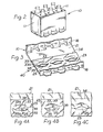
- Figure 2 is a perspective view of the article carrier of the present invention having a plurality of articles such as bottles, supported therein after completion of forming the blank into the carrier;
- Figure 3 is a fragmentary inside perspective view of the carrier showing the relation of the bottom panels of the blank when in proper overlapping and locked relation;
- Figure 4A is an enlarged fragmentary plan view showing in more detail the threading of the tongue through the transversely elongated slit furthest from the edge of the opposite closure panel;
- Figure 4B is a similar fragmentary plan view showing the relationship of the closure panels following the punching of the locking tab in the slit nearest the edge of the opposite closure panel; and
- Figure 4C is an underside fragmentary plan view showing the relationship of the locking tab and the tongue within the transversely elongated slits of the blank.
- Referring to the drawings and particularly to Figure 2, there is shown an
article carrier 10 of the wraparound type for a plurality of articles such asbottles 11, for. example, arranged in one or more rows. As shown in Figure 2, thebottles 11 are arranged in two rows, but there can be only a single row or more than two rows. - The
article carrier 10 is formed from an elongated blank 12 (see Figure 1) of a suitable foldable sheet material such as paperboard, for example. The elongated blank 12 has asingle top panel 14 withcircular apertures 13 cut therein to accommodate the necks of thebottles 11. -
Side panels 16 are articulated or hingedly joined to opposite sides of thetop panel 14 along a pair oftop fold lines 15. Theside panels 16 are designed to be substantially vertical in the completedarticle carrier 10, as shown in Figure 2. - A
bottom closure panel 21 is articulated or hingedly joined to one of theside panels 16 along a fold line 22 (see top of Figure 2). Another bottom orclosure panel 23 is articulated or hingedly joined to the other of theside panels 16 byfold line 24. - The
bottom panel 21 has a plurality of transversely spaced lock units each including a tongue 25 (three shown in Figure 1) with the number oftongues 25 preferably being equal to the number of bottles 11 (see Figure 2) in each of the rows. The tongues 25 (see Figure 1) are spaced from each other byrecessed edge portions 26 between the tongues. - The outer ends of the edge along the
panel 21 adjacent theend tongues 25 are formed by anedge extension 30 and connect to longitudinal side edges 31 and 32 of the elongated blank 12. Thebottom panel 21 thus has its terminal edge defined by the edges of thetongues 25, the recessededge portions 26 and the connectingedge extensions 30. - The
bottom panel 23 has a plurality of pairs of adjacent, substantially parallel, transversely elongated slits for receiving the corresponding locking units when the closure panels are in proper overlapping relation. - First transversely elongated
slits 33 are formed adjacent theterminal edge 34 of thebottom panel 23, between theterminal edge 34 and second transversely elongated slits 35. - The bottom panel material disposed between the
first slits 33 andsecond slits 35 forms aprotector strap 38. Thefirst slit 33 includesrelief extensions 33a at each end thereof, and theseextensions 33a extend toward said adjacent second slit35 at an angle ofsubstantially 135° from theslit 33. Thesecond slit 35 includesrelief slits 35a at each end thereof, and theserelief slits 35a extend toward said adjacentfirst slit 33 at an angle of substantially 90° from said second slit 35; the corner is rounded to minimize the tendency to tear the paperboard. - The
relief extensions 33a andrelief slits 35a further define the bridges at the ends of theprotector strap 38. The bridges (see Figures 1 and 4) have a length substantially equal to the combined length ofrelief extensions 33a and slits 35a to insure maximum strength while at the same time providing the required relief for ease of engaging the lock units. - Each of the
tongues 25 is threadable into one of the transverselyelongated slits 35 when the bottom orclosure tongue 25 overlies the inner transverse edge of thecorresponding slit 35 so as to have a relatively large area of overlapping contact (Figure 4A). As can be seen, the edge of theslit 35 forms a locating edge for the locking unit. - The
bottom panel 21 has a set of locking tabs, designated by thereference numeral 39; a single locking tab being longitudinally aligned with each of thetongues 25. The lockingtabs 39 are formed through slitting thebottom panel 21 and may be bifurcated, as shown in the preferred embodiment. The lockingtabs 39 and thetongues 25 together form the locking unit, generally designated by the reference numeral 40 (Figures 1 and 3). - When the elongated blank 12 is folded to form the
carrier 10 with thebottles 11 therein, thebottom panels tongue 25 is first threaded within the corresponding transversely elongated slit 35, thelocking tab 39 underlies the closure panel 23 (see Figure 4A looking from inside). - The
locking tab 39 is then punched (from below) through the transversely elongated slit 33 so that thelocking tab 39 directly overliesclosure panel 23 thereby providing edge to edge engagement with the transverse edge (see Figure 4B). Further, theprotector strap 38 overlies thetab 39 to hold the tab in locked engagement while providing additional strength and support to thecarrier 10. A fragmentary view of the fully threadedarticle carrier 10 from below is shown in Figure 4C. - In forming the
carrier 10 from the elongated blank 12, the elongated blank 12 is first placed over the necks of thebottles 11. When the elongated blank 12 is properly seated horizontaly on thebottles 11, theside panels 16 are folded down the sides. Then, thebottom panels botles 11. Thetongues 25 are threaded into the transverselyelongated slits 35 and the lockingtabs 39 are punched into the longitudinally aligned transversely elongated slits33 by forcing with punching wheels (not shown) past the transverse edge of theslits 33. - The locking arrangement of the present invention enables a relatively large edge to edge locating and locking engagement in a transverse direction. A firm, secure and protected locking engagement safe against inadvertent release is provided. The improved performance is obtained without any increase in paperboard in the blank over that used in the original Pierce carrier shown in the previous Certipak patent cited above, and considerably less than that used in later patents seeking to improve the strength.
- The use of slits rather than apertures, as in the prior art, negates the need to strip the trim from the closure panel that receives the locking unit. This not only reduces the manufacturing costs incurred by carton manufacturers, but provides a
protective strap 38 overlying the locking tab along the interior of the carrier to hold the tab in locked engagement and provide extra strength. This is a particularly important consideration under refrigerated conditions when the paper absorbs moisture and loses stiffness. - The lock structure of the present invention also provides convenient mechanical threading and punching for adaptation with state of the art machines and improved automation techniques.
- The foregoing description of the preferred embodiment of the invention has been presented for purposes of illustration and description. It is not intended to be exhaustive or to limit the invention to the precise form disclosed. Obvious modifications and variations are possible in light of the above teachings. For example, the blank could be provided with slits having different shapes and configurations. The edges of the blank may not necessarily be as shown but could include other shapes and separate angled portions.
Claims (4)
Applications Claiming Priority (2)
| Application Number | Priority Date | Filing Date | Title |
|---|---|---|---|
| US48867383A | 1983-04-26 | 1983-04-26 | |
| US488673 | 1983-04-26 |
Publications (2)
| Publication Number | Publication Date |
|---|---|
| EP0123358A1 EP0123358A1 (en) | 1984-10-31 |
| EP0123358B1 true EP0123358B1 (en) | 1987-12-02 |
Family
ID=23940662
Family Applications (1)
| Application Number | Title | Priority Date | Filing Date |
|---|---|---|---|
| EP84200548A Expired EP0123358B1 (en) | 1983-04-26 | 1984-04-18 | Combined lock structure for article carrier |
Country Status (5)
| Country | Link |
|---|---|
| EP (1) | EP0123358B1 (en) |
| JP (1) | JPS59225116A (en) |
| AU (1) | AU560403B2 (en) |
| CA (1) | CA1236804A (en) |
| DE (1) | DE3467882D1 (en) |
Families Citing this family (3)
| Publication number | Priority date | Publication date | Assignee | Title |
|---|---|---|---|---|
| GB8700777D0 (en) * | 1987-01-14 | 1987-02-18 | Mead Corp | Panel interlocking arrangement |
| DE9206092U1 (en) * | 1992-05-06 | 1992-08-27 | Europa Carton Ag, 2000 Hamburg, De | |
| JP6163873B2 (en) * | 2013-05-21 | 2017-07-19 | 凸版印刷株式会社 | carton |
Citations (1)
| Publication number | Priority date | Publication date | Assignee | Title |
|---|---|---|---|---|
| US2990997A (en) * | 1958-07-15 | 1961-07-04 | Continental Can Co | Paperboard carrier |
Family Cites Families (5)
| Publication number | Priority date | Publication date | Assignee | Title |
|---|---|---|---|---|
| US3223308A (en) * | 1962-09-27 | 1965-12-14 | Continental Can Co | Can carrier with reinforcing means |
| US3374938A (en) * | 1967-05-05 | 1968-03-26 | Certipak Corp | Construction of interlocking bottom panels for wraparound type bottle or can carriers |
| US4164286A (en) * | 1978-02-10 | 1979-08-14 | Federal Paper Board Company, Inc. | Tapered cup package |
| US4200220A (en) * | 1978-10-27 | 1980-04-29 | Federal Paper Board Co., Inc. | Wrap-around paperboard carrier with latching and locking panels |
| JPS5691263U (en) * | 1979-12-17 | 1981-07-21 |
-
1984
- 1984-04-18 EP EP84200548A patent/EP0123358B1/en not_active Expired
- 1984-04-18 DE DE8484200548T patent/DE3467882D1/en not_active Expired
- 1984-04-25 CA CA000452743A patent/CA1236804A/en not_active Expired
- 1984-04-26 AU AU27288/84A patent/AU560403B2/en not_active Ceased
- 1984-04-26 JP JP59085072A patent/JPS59225116A/en active Granted
Patent Citations (1)
| Publication number | Priority date | Publication date | Assignee | Title |
|---|---|---|---|---|
| US2990997A (en) * | 1958-07-15 | 1961-07-04 | Continental Can Co | Paperboard carrier |
Also Published As
| Publication number | Publication date |
|---|---|
| DE3467882D1 (en) | 1988-01-14 |
| JPS59225116A (en) | 1984-12-18 |
| EP0123358A1 (en) | 1984-10-31 |
| CA1236804A (en) | 1988-05-17 |
| AU560403B2 (en) | 1987-04-02 |
| JPH0246467B2 (en) | 1990-10-16 |
| AU2728884A (en) | 1984-11-01 |
Similar Documents
| Publication | Publication Date | Title |
|---|---|---|
| EP0728110B1 (en) | Wrap-around carrier with article heel lock | |
| US5520283A (en) | Warp-around carrier with article retaining flaps | |
| EP1384673B1 (en) | Locking arrangement for panels | |
| EP0655981B1 (en) | Bottle carrier | |
| US5180100A (en) | Wraparound carton lock | |
| EP0171229B1 (en) | Bottle carrier | |
| US3669342A (en) | Article carrier | |
| US4875586A (en) | Multipack with top panel keel | |
| US4574997A (en) | Keel and lock for wraparound article carrier | |
| JPH10503158A (en) | Wrap-around carrier with corner end restraint | |
| WO1992004251A1 (en) | Wrap-around carrier with article retainer | |
| WO1998056683A1 (en) | Carrier with article retaining means | |
| US5782343A (en) | Warp-around carrier with improved locking means | |
| US4355717A (en) | Wraparound article carrier with adjustable girth | |
| US3397776A (en) | Wraparound carton and blank therefor | |
| EP0059104B1 (en) | Article carrier | |
| US4609143A (en) | Combined lock structure for article carrier | |
| EP0123358B1 (en) | Combined lock structure for article carrier | |
| EP1472154B1 (en) | Carton with overlapped base panels and blank therefor |
Legal Events
| Date | Code | Title | Description |
|---|---|---|---|
| PUAI | Public reference made under article 153(3) epc to a published international application that has entered the european phase |
Free format text: ORIGINAL CODE: 0009012 |
|
| AK | Designated contracting states |
Designated state(s): DE FR GB IT |
|
| 17P | Request for examination filed |
Effective date: 19841019 |
|
| GRAA | (expected) grant |
Free format text: ORIGINAL CODE: 0009210 |
|
| AK | Designated contracting states |
Kind code of ref document: B1 Designated state(s): DE FR GB IT |
|
| ITF | It: translation for a ep patent filed |
Owner name: DR. ING. A. RACHELI & C. |
|
| REF | Corresponds to: |
Ref document number: 3467882 Country of ref document: DE Date of ref document: 19880114 |
|
| ET | Fr: translation filed | ||
| PLBE | No opposition filed within time limit |
Free format text: ORIGINAL CODE: 0009261 |
|
| STAA | Information on the status of an ep patent application or granted ep patent |
Free format text: STATUS: NO OPPOSITION FILED WITHIN TIME LIMIT |
|
| 26N | No opposition filed | ||
| ITTA | It: last paid annual fee | ||
| REG | Reference to a national code |
Ref country code: GB Ref legal event code: IF02 |
|
| PGFP | Annual fee paid to national office [announced via postgrant information from national office to epo] |
Ref country code: FR Payment date: 20020311 Year of fee payment: 19 |
|
| PGFP | Annual fee paid to national office [announced via postgrant information from national office to epo] |
Ref country code: DE Payment date: 20020314 Year of fee payment: 19 |
|
| PGFP | Annual fee paid to national office [announced via postgrant information from national office to epo] |
Ref country code: GB Payment date: 20030313 Year of fee payment: 20 |
|
| PG25 | Lapsed in a contracting state [announced via postgrant information from national office to epo] |
Ref country code: DE Free format text: LAPSE BECAUSE OF NON-PAYMENT OF DUE FEES Effective date: 20031101 |
|
| PG25 | Lapsed in a contracting state [announced via postgrant information from national office to epo] |
Ref country code: FR Free format text: LAPSE BECAUSE OF NON-PAYMENT OF DUE FEES Effective date: 20031231 |
|
| REG | Reference to a national code |
Ref country code: FR Ref legal event code: ST |
|
| PG25 | Lapsed in a contracting state [announced via postgrant information from national office to epo] |
Ref country code: GB Free format text: LAPSE BECAUSE OF EXPIRATION OF PROTECTION Effective date: 20040417 |
|
| REG | Reference to a national code |
Ref country code: GB Ref legal event code: PE20 |