EP0122993A2 - Klein-Gasverdichter mit Festkörperbauelementen - Google Patents
Klein-Gasverdichter mit Festkörperbauelementen Download PDFInfo
- Publication number
- EP0122993A2 EP0122993A2 EP83305640A EP83305640A EP0122993A2 EP 0122993 A2 EP0122993 A2 EP 0122993A2 EP 83305640 A EP83305640 A EP 83305640A EP 83305640 A EP83305640 A EP 83305640A EP 0122993 A2 EP0122993 A2 EP 0122993A2
- Authority
- EP
- European Patent Office
- Prior art keywords
- channel
- blocks
- gas
- elastomer
- electric field
- Prior art date
- Legal status (The legal status is an assumption and is not a legal conclusion. Google has not performed a legal analysis and makes no representation as to the accuracy of the status listed.)
- Withdrawn
Links
- 229920001971 elastomer Polymers 0.000 claims abstract description 54
- 239000000806 elastomer Substances 0.000 claims abstract description 54
- 230000005684 electric field Effects 0.000 claims abstract description 45
- 210000004027 cell Anatomy 0.000 claims description 106
- 229910010293 ceramic material Inorganic materials 0.000 claims description 20
- 238000006073 displacement reaction Methods 0.000 claims description 14
- 210000000635 valve cell Anatomy 0.000 claims description 6
- 239000007789 gas Substances 0.000 abstract description 66
- 239000000919 ceramic Substances 0.000 abstract description 19
- 238000007906 compression Methods 0.000 abstract description 18
- 230000006835 compression Effects 0.000 abstract description 17
- 230000000694 effects Effects 0.000 abstract description 6
- 230000002572 peristaltic effect Effects 0.000 abstract description 5
- 230000004913 activation Effects 0.000 abstract description 2
- 230000004044 response Effects 0.000 abstract description 2
- 239000000463 material Substances 0.000 description 18
- 238000000034 method Methods 0.000 description 14
- IJGRMHOSHXDMSA-UHFFFAOYSA-N Atomic nitrogen Chemical compound N#N IJGRMHOSHXDMSA-UHFFFAOYSA-N 0.000 description 9
- 238000005057 refrigeration Methods 0.000 description 8
- UFHFLCQGNIYNRP-UHFFFAOYSA-N Hydrogen Chemical compound [H][H] UFHFLCQGNIYNRP-UHFFFAOYSA-N 0.000 description 5
- 230000009471 action Effects 0.000 description 5
- 239000001257 hydrogen Substances 0.000 description 4
- 229910052739 hydrogen Inorganic materials 0.000 description 4
- 229910052757 nitrogen Inorganic materials 0.000 description 4
- 230000008569 process Effects 0.000 description 4
- 239000007787 solid Substances 0.000 description 4
- 238000001125 extrusion Methods 0.000 description 3
- 239000001307 helium Substances 0.000 description 3
- 229910052734 helium Inorganic materials 0.000 description 3
- SWQJXJOGLNCZEY-UHFFFAOYSA-N helium atom Chemical compound [He] SWQJXJOGLNCZEY-UHFFFAOYSA-N 0.000 description 3
- 230000010287 polarization Effects 0.000 description 3
- 238000005086 pumping Methods 0.000 description 3
- 238000007789 sealing Methods 0.000 description 3
- 239000000243 solution Substances 0.000 description 3
- 229910002659 PbMg1/3Nb2/3O3 Inorganic materials 0.000 description 2
- 230000001133 acceleration Effects 0.000 description 2
- 238000001816 cooling Methods 0.000 description 2
- 238000005516 engineering process Methods 0.000 description 2
- 239000007788 liquid Substances 0.000 description 2
- 229920000260 silastic Polymers 0.000 description 2
- 238000002336 sorption--desorption measurement Methods 0.000 description 2
- 238000010345 tape casting Methods 0.000 description 2
- 230000007704 transition Effects 0.000 description 2
- RYGMFSIKBFXOCR-UHFFFAOYSA-N Copper Chemical compound [Cu] RYGMFSIKBFXOCR-UHFFFAOYSA-N 0.000 description 1
- 230000005668 Josephson effect Effects 0.000 description 1
- 229910003781 PbTiO3 Inorganic materials 0.000 description 1
- 229910020698 PbZrO3 Inorganic materials 0.000 description 1
- 235000014676 Phragmites communis Nutrition 0.000 description 1
- 230000003321 amplification Effects 0.000 description 1
- 239000003985 ceramic capacitor Substances 0.000 description 1
- 230000008859 change Effects 0.000 description 1
- 239000003795 chemical substances by application Substances 0.000 description 1
- 230000001684 chronic effect Effects 0.000 description 1
- 239000004020 conductor Substances 0.000 description 1
- 238000010276 construction Methods 0.000 description 1
- 238000011109 contamination Methods 0.000 description 1
- 229910052802 copper Inorganic materials 0.000 description 1
- 239000010949 copper Substances 0.000 description 1
- 230000008878 coupling Effects 0.000 description 1
- 238000010168 coupling process Methods 0.000 description 1
- 238000005859 coupling reaction Methods 0.000 description 1
- 230000001351 cycling effect Effects 0.000 description 1
- 238000010586 diagram Methods 0.000 description 1
- 229910001873 dinitrogen Inorganic materials 0.000 description 1
- NKZSPGSOXYXWQA-UHFFFAOYSA-N dioxido(oxo)titanium;lead(2+) Chemical compound [Pb+2].[O-][Ti]([O-])=O NKZSPGSOXYXWQA-UHFFFAOYSA-N 0.000 description 1
- 239000013536 elastomeric material Substances 0.000 description 1
- 238000010438 heat treatment Methods 0.000 description 1
- 150000002431 hydrogen Chemical class 0.000 description 1
- 238000005470 impregnation Methods 0.000 description 1
- HFGPZNIAWCZYJU-UHFFFAOYSA-N lead zirconate titanate Chemical compound [O-2].[O-2].[O-2].[O-2].[O-2].[Ti+4].[Zr+4].[Pb+2] HFGPZNIAWCZYJU-UHFFFAOYSA-N 0.000 description 1
- 230000005291 magnetic effect Effects 0.000 description 1
- 238000004519 manufacturing process Methods 0.000 description 1
- 239000002184 metal Substances 0.000 description 1
- 229910052751 metal Inorganic materials 0.000 description 1
- 229910052987 metal hydride Inorganic materials 0.000 description 1
- 150000004681 metal hydrides Chemical class 0.000 description 1
- 238000003199 nucleic acid amplification method Methods 0.000 description 1
- 229920002120 photoresistant polymer Polymers 0.000 description 1
- 230000000063 preceeding effect Effects 0.000 description 1
- 239000004065 semiconductor Substances 0.000 description 1
- 239000006104 solid solution Substances 0.000 description 1
- 238000001179 sorption measurement Methods 0.000 description 1
- 239000010457 zeolite Substances 0.000 description 1
Images


Classifications
-
- F—MECHANICAL ENGINEERING; LIGHTING; HEATING; WEAPONS; BLASTING
- F04—POSITIVE - DISPLACEMENT MACHINES FOR LIQUIDS; PUMPS FOR LIQUIDS OR ELASTIC FLUIDS
- F04B—POSITIVE-DISPLACEMENT MACHINES FOR LIQUIDS; PUMPS
- F04B35/00—Piston pumps specially adapted for elastic fluids and characterised by the driving means to their working members, or by combination with, or adaptation to, specific driving engines or motors, not otherwise provided for
-
- Y—GENERAL TAGGING OF NEW TECHNOLOGICAL DEVELOPMENTS; GENERAL TAGGING OF CROSS-SECTIONAL TECHNOLOGIES SPANNING OVER SEVERAL SECTIONS OF THE IPC; TECHNICAL SUBJECTS COVERED BY FORMER USPC CROSS-REFERENCE ART COLLECTIONS [XRACs] AND DIGESTS
- Y10—TECHNICAL SUBJECTS COVERED BY FORMER USPC
- Y10S—TECHNICAL SUBJECTS COVERED BY FORMER USPC CROSS-REFERENCE ART COLLECTIONS [XRACs] AND DIGESTS
- Y10S505/00—Superconductor technology: apparatus, material, process
- Y10S505/825—Apparatus per se, device per se, or process of making or operating same
- Y10S505/888—Refrigeration
-
- Y—GENERAL TAGGING OF NEW TECHNOLOGICAL DEVELOPMENTS; GENERAL TAGGING OF CROSS-SECTIONAL TECHNOLOGIES SPANNING OVER SEVERAL SECTIONS OF THE IPC; TECHNICAL SUBJECTS COVERED BY FORMER USPC CROSS-REFERENCE ART COLLECTIONS [XRACs] AND DIGESTS
- Y10—TECHNICAL SUBJECTS COVERED BY FORMER USPC
- Y10S—TECHNICAL SUBJECTS COVERED BY FORMER USPC CROSS-REFERENCE ART COLLECTIONS [XRACs] AND DIGESTS
- Y10S505/00—Superconductor technology: apparatus, material, process
- Y10S505/825—Apparatus per se, device per se, or process of making or operating same
- Y10S505/91—Pump
Definitions
- the present invention relates to a gas compressor and, more particularly, to such a device capable of miniaturization and requiring relatively low electrical power input.
- cryoelectronic devices include, for example, extremely sensitive magnetometers, gradiometers, bolometers, voltage standards, current comparators, rf attenuators and logic elements. See, e.g., IEEE Trans. On Magnetics, Vol. 17, No. 1, Jan., 1981, Sessions BC, CC, SC, HC, IC. These devices typically operate at temperatures below about 22K (i.e., 22 degrees absolute), and the power dissipated by such devices is characteristically on the order of microwatts.
- a Joule-Thompson expansion cycle is commonly staged onto a Gifford-McMahon refrigerator, utilizes a 20.7 to 0.03 bar (300 to 1/2 psig) expansion, and delivers approximately three watts of useful refrigeration at 4.2K.
- Adsorption-desorption pumps operate on the principle that certain solids, such as zeolites or metal hydrides, selectively adsorb certain gases at a first temperature and pressure, and desorb them at a second, higher temperature and pressure. Therefore, by thermally cycling such a solid with appropriate valving, gas compression is achieved.
- These pumps are disadvantageous in that long cycle times are involved, typically on the order of 30 minutes, due to slow adsorption and heat-transfer rates. Further, the overall compression efficiency of such pumps is low.
- a gas compressor ideally matched to the requirements of the micro-refrigerators described above.
- Such a compressor should be of small size, commensurate with the small size of the microminiature refrigerators. Further, the compressor should have relatively modest electric power requirements, and should be capable of supplying sufficiently large gas flow rates. Moreover, the compressor should be applicable to any gas.
- an apparatus for compressing a ⁇ gas including a block of electrostrictive piezoelectric ceramic material having a first end, an elastomer disposed along said first end of the block, means defining a channel having said elastomer as at least one wall thereof, means for selectively applying an electric field to said block, and means constraining said block such that application of said electric field to said block causes displacement thereof against said elastomer, extruding said elastomer into a closed relationship with said channel defining means.
- the present invention discloses a solid- state, room-temperature gas compressor deriving its compression action from the relatively large dimensional changes that occur in certain electrostrictive and high strain capability piezoelectric ceramic materials when an electric field is appropriately applied. While the present invention will be described in terms of electrostrictive ceramic materials, it will be understood that reference to electrostrictive materials in this specification will include high strain capability ceramic materials.
- the apparatus includes a block of such ceramic material, and an elastomer disposed along one end of the block.
- the apparatus further includes a means for defining a channel, wherein the elastomer forms at least one wall thereof, and a means for selectively applying an electric field to the ceramic block.
- the block is constrained such that application of the electric field to the block causes its displacement against the elastomer. This displacement extrudes the elastomer into a closing relationship with the channel.
- the apparatus may include a pair of blocks of a ceramic material, disposed in an opposing relationship so as to form a gap ⁇ therebetween.
- the elastomer is disposed within and at least partially fills the gap.
- the blocks are constrained such that application of the electric field causes the displacement of the blocks against the elastomer.
- the electrostrictive ceramic material may be Pb M 0 3 , where M is a member selected from the group consisting of Zr, Ti, (Mg 1/3 N 2/3 ) and ( Sc l/3 Ta 2/3 ), or appropriate combination thereof.
- the material may be a high strain capability piezoelectric ceramic material.
- Suitable piezoelectric materials include so-called donor-doped soft piezoelectric ceramics from the lead zirconate and lead titanate families. These soft piezoelectric materials have low coercivity and high d33 coefficients. Examples are PZT-5A and PZT-5H piezoelectric ceramics available from Vernitron Corp.
- the apparatus may further include an inlet valve means for selectively introducing the quantity of gas to the channel, and an outlet valve means for selectively allowing the gas to exit the channel.
- the means for applying the electric field may include a plurality of metallic plates disposed in a substantially parallel, spaced relationship within'each of the ceramic blocks.
- the apparatus may include a plurality of cells, where each cell includes a pair of ceramic blocks defining a gap therebetween, an elastomer disposed within the gap, means defining a channel having the elastomer as at least one wall thereof, and means for applying an electric field to the blocks, wherein the blocks are constrained such that application of the field causes displacement against the elastomer, extruding it into a closing relationship with the channel.
- the cells are arranged sequentially, such that each channel of each cell communicates with the channel of the immediately preceeding and succeeding cells.
- a means for selectively controlling the electric field application means of each of the cells is provided for sequential closings of each of the channels. The sequential ciosings operate to peristaltically compress a gas introduced into the channels.
- An additional cell may be provided adjacent the first of the sequential cells, for operation as an inlet valve.
- a cell may be provided adjacent the last of the sequential cells, for operation as an outlet valve.
- the means for electric field control is further adapted to control selectively the electric field application means of the inlet valve cell and the outlet valve cell.
- the apparatus may further have the volume defined by each channel of each sequential cell smaller than the volume defined by the channel of the immediately preceding cell.
- One method for compressing the gas includes the steps of providing a plurality of channels connected together in sequence, where each channel has at least one wall of an elastomeric material, and the channels cooperate to define a continuous passage having a first and a second end.
- a quantity of gas is introduced into the passageway, and the passageway is closed at the first and second ends.
- Each of the elastomeric walls is extruded into each of the channels, so as to close the channel. The extruding is performed sequentially from the channel adjacent the first end up to but not including the channel adjacent the second end.
- the gas within the passageway is compressed into the channel adjacent to the second end.
- an object of the present invention to provide one or more of the following, namely to provide an apparatus for compressing a gas having a block of an electrostrictive or piezoelectric ceramic material, an elastomer, a channel, and a means for applying an electric field to the block, whereby the block displaces and extrudes the elastomer so as to close the channel; to provide a gas compressor wherein the compression effect is derived from the peristaltic activation of several cells, wherein each cell utilizes the extrusion of an elastomer into a channel defined within that cell such that the overall effect is to compress the gas into the final cell; to provide such an apparatus that is more efficient than conventional mechanical compressors and is suitable for miniaturization; to provide such an apparatus which is self-valving and self-lubricating and thereby free of the chronic contamination problems associated with conventional compressor seals and valves; and to provide such an apparatus wherein the gas compression is performed relatively isothermally.
- the gas compressor emdying the present invention utilizes the electrostrictive or piezoelectric properties of several potential ceramic materials.
- Electrostrictive materials display relatively large induced strains, ⁇ /L, under the action of an applied electric field E.
- ⁇ is the incremental change of the dimension L, according to which where Qij is the electrostrictive coefficient and P j is the polarization introduced by the field E j .
- the subscripts i and j in Eq. (1) reflect the fact that the electrostrictive effect occurs three-dimensionally throughout the solid.
- ( 6/L )p er p and ( ⁇ /L) para are the strains induced perpendicular and parallel to the polarization, respectively.
- the polarization is related to the electric field by where ⁇ o and ⁇ are the dielectric permittivities of free space and of the electrostrictive material, respectively, and ⁇ is E-field dependant. Therefore, for an isotropic ceramic body as used in the present . invention,
- the electrostrictive ceramic materials used in the present invention are PbZrO 3 , PbTiO 3 , PbMgl/3Nb2/303, or PbSc l/3 Ta 2/3 0 3 or appropriate combinations thereof.
- Fig. 1 a permittivity-temperature plot typical of the most preferred of these materials, PbMg 1/3 Nb 2/3 O 3 , is presented showing the frequency dependance of the permittivity.
- ⁇ achieves very large values, on the order of 20,000, as shown in Fig. 1.
- the electrostrictive coefficient Q ij may be relatively modest, the strains are, in fact, very large because of the multiplying ⁇ 2 factor, as shown in Eqs. (5) and (6).
- -these materials achieve strains in the range 4 x 10- 4 to 10 -3 at kHz frequencies in the neighborhood of the transition temperature Tcfor E-field strengths of approximately 20 kV/cm.
- the transition temperature T c can be widely adjusted by using appropriate solid solutions of the ceramic materials set out above, including adjusting T c to 25°C.
- the compressor may be constructed using other suitable electrostrictive materials or piezoelectric ceramics having high strain capability.
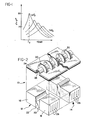
- the large electrostrictive (or piezoelectric) strains obtainable with these materials are used to obtain a peristaltic pumping action for gas compression, as illustrated in Fig. 2.
- the gas compressor 10 is composed of a plurality of cells, or sections, two of which are shown in the exploded view of Fig. 2, indicated at 12 and 14.
- Each of the cells of the compressor 10, for example cell 12, includes a pair of blocks of the ceramic material 16 and 18.
- the blocks 16 and 18 are mounted in a spaced relationship such that they define a gap 20 between their opposing faces.
- Gap 20 is filled with an elastomer material 22, which may preferably be Dow Cornrng Silastic TR-55.
- a covering plate 24 is mounted to the top of blocks 16 and 18.
- An inverted channel 26 is defined lengthwise along cover plate 24, such that it communicates with gap 20 formed between blocks 16 and 18.
- An electric field is selectively applied to the two opposing ceramic blocks 16 and 18.
- the blocks are constrained by an appropriate frame (not shown) such that the motion of the blocks is directed against the elastomer 22 filling gap 20.
- the elastomer 22 is electrostrictively "pinched", which in turn causes the elastomer to be extruded out of the gap 22 and into the channel 26. defined in covering plate 24.
- Fig. 2 It can be seen in Fig. 2 by comparing the respective portions of elastomer 22, that the blocks of cell 14 have an electric field applied thereto, while the blocks 16 and 18 of cell 12 have no field applied.
- the pumping action of the gas compressor 10 derives from forcing the gas out of the channel section of cell 14 into the channel section of cell 12 by applying an electric field to cell 14, thereby closing its respective channel.
- the preferred means for applying electric fields to the ceramic blocks is by metallic plate electrodes 28 interspersed within each ceramic block.
- Multilayering of plate electrodes is well-known in the art for the manufacture of ceramic capacitors, and the blocks with interspersed electrodes may be preferably constructed by known "tape-casting" methods. Using such a method, the plate electrodes are typically separated by ceramic material of approximately 2 x 10 -3 to 10 -2 cm thickness. Consequently, the voltage supply for a gas compressor according to the preferred embodiment would be on the order of 40 to 200 volts.
- each block in fact includes two alternating sets of plate electrodes, with one set for voltage and the other for ground. All ground electrodes in all cells may be wired in common, thereby facilitating the switching of the application of the electric field from cell to cell.
- Each cell of the gas compressor 10 must be bonded together to avoid gas loss along the cell interfaces, and the elastomer used to fill gap 20 may be used for this bonding as well.
- An elastomeric bonding between the cells allows one cell to elongate electrostrictively with the minimal mechanical coupling to adjacent cells, thereby facilitating efficient pumping action.
- the covering plate 24 must be hermetically sealed to the cells by an elastic medium, and the preferred elastomer may be used for this bond as well.
- the covering plate 24 is preferably made from a metal, most preferably copper, and outfitted with a plurality of cooling fins 30 constructed of the same material. Construction of plate 24 and fins 30 of the preferred material facilitates the conduction away and dissipation of heat generated in the gas by the compression process.
- the entire assembly of cells and cover plate can be vacuum-impregnated with the elastomer by methods well-known in the elastomer art.
- the integrity of the channel 26 can be preserved during this process, for example, by preinserting a solid rod into the channel space, vacuum impregnating, and then removing the rod. An appropriate release agent applied to the surface of the rod would facilitate its removal.
- the channel diameter is preferably on the order of millimeters, even for cells containing relatively high-pressure gas.
- the compressor is self-valving, since the elastomer is electrostrictively extruded into a closing relationship with the channel 26 defined in covering plate 24. So long as this closing relationship results in elastomer-channel interfaces on the order of microns, the channel section is effectively valved.
- each cell of compressor 10 may be constructed with a single block of the electrostrictive material disposed adjacent the elastomer-filled gap 20.
- a rigid side wall would be provided for gap 20 opposite the block, and the elastomer would be extruded by the block compressing it against the rigid wall.
- a gas compressor constructed according to the present invention consisting for _ purposes of example of ten cells similar to those in shown in Fig. 2 as cells 12 and 14, is described as follows. It will be seen that in the exemplary ten-cell compressor, the first cell and the tenth cell operate effectively as an inlet valve and an outlet valve, respectively. It will be understood that references to closing and opening of the various cells refers to the extrusion and release of the elastomer of the various cells into and out of the respective channels. The extrusion is, of course, performed in response to the application of an electric field to the various ceramic blocks.
- the tenth cell is closed, while all other cells are opened, and a low pressure gas is directed into and allowed to fill the entire passageway defined by the various sequentially connected channels.
- the first cell is then closed, thereby retaining a quantity of gas within the passageway.
- the second cell is next closed, followed by the third, the fourth, and so on, until all the gas is compressed into the ninth cell.
- the tenth cell is opened simultaneously with the closing of the ninth cell, and the compressed gas is exhausted.
- One variation on this process is to open the first cell, second, and so forth as the gas is compressed into the subsequent cells, so as to reduce the overall" cycle time of the compressor. Additionally, it is advantageous to arrange the sequential addressing of the cells such that the closure of the higher-pressure cells takes place more slowly than the closure of the lower pressure cells so as to dissipate the heat of compression uniformly along the entire passageway.
- peristaltic gas compressor of the present invention may be illustrated by considering a realistic model as an example of the preferred embodiment. While this model is an approximation in the fine details, it gives a reliable estimation of the major features of the invention.
- Each cell includes a pair of ceramic blocks 36 - and 38, each being of a length L, a thickness l , and a heighth H.
- a gap 40 formed between blocks 36 and 38 has an "open" gap width d, and a "closed” gap d-2 6.
- the channel 46 for each of cells 32 and 34 has a radius R, with R greater than d/2, such that the circle defined by channel 46 extends into the gap 40 an amount h o in the open state, and h E in the closed state.
- the radius R is a close approximation of the actual radii R o and RE , respectively, and will be used throughout the specification.
- the elastomer 42 of the open cell 32 is formed within gap 40 such that its upper surface coincides with the circle defined by channel 46.
- channel 46 In the closed cell 34, it can be seen that the displacement of blocks 36 and 38 extrudes elastomer 42 so as to completely fill channel 46. While channel 46 in this example has been illustrated as cylindrical for convenience, it will be appreciated that other channel shapes may be chosen to minimize the total deformation required of the elastomer which may be advantageous in reducing fatigue and extending pump life.
- Eq. (9) shows that the height H is an important amplification variable, since R 2 a H .
- the displacement 6 is related to L from Eq. (5):
- a ten cell compressor wherein the first and tenth cells are the inlet and outlet valves, respectively, such as that described above, is once again considered.
- This displacement ⁇ corresponds to a strain value of 7 x 10 -4 which represents a middle value of the range of realizable electrostrictive strains for the materials described above.
- the compression ratio for the gas compressor is selected to be 25:1. Since this compression is performed by effectively reducing the gas volume, the ideal gas relationship under isothermal conditions may be considered:
- the volume of the j th cell channel, from Fig. 3, is ⁇ R l j , and for the 25:1 compressiori ratio where P 2 is the initial pressure when the gas to be compressed occupies the second through the ninth cells.
- Figs. 4 and 5 show the solution for this model.
- Fig. 4 shows the stepwise variation of X o and X E along the passageway
- Fig. 5 shows scale drawings of the various values of R j, Hj, and l j .
- the telescoping feature of the cells and the cell channels is seen from Fig. 5, where it may be seen that the heights H j attenuate as well.
- Compression of the gas from the eighth into the ninth cell involves the largest pressure drop, and an estimate of the pressure drop due to turbulent flow in this process is approximately 0.16 atm.
- the inertial pressure drop required to accelerate the gas from the eighth to ninth cell may be estimated to be approximately 1.1 atm, assuming that this process takes place in approximately 10 -4 sec (i.e., a 1 kHz cycle). These values are quite acceptable in view of the 25 atm outlet pressure of the gas leaving the compressor.
- the work done in accelerating the gas is smallest in closing the second cell, and largest in closing the eighth cell.
- inertial work terms are dissipated as heat, and an estimate may be made showing that the work terms in closing the second and eighth cells would be equivalent if the eighth cell closed approximately 3-1/2 times slower than the second cell.
- the electronic addressing of the electric fields supplied to the cells can be staged such that the inertial work heating is uniform along the entire passageway, and the gas compression is nearly isothermal.
- the elastomer is accelerated into and out of the channel at each cell, and this acceleration stresses the elastomer. Assuming times on the order of 10 -4 sec for these accelerations, the tension between the elastomer and the ceramic member may be estimated to be approximately 0.08 bar (1.2 psi). This represents a very modest value in comparison to the tensile strength of typical elastomers which, for example, in the case of the preferred Dow Corning Silastic TR-55, is 100. bar (1450 psi).
- the mass flow rates through the examplary model compressor may be estimated for various gases. From Eqs. (15) through (18), the total volume of the channels of the second through the ninth cells is 0.202 cm 3 and this value represents the volume of gas compressed per cycle. Assuming that the gas in the channels is initially at STP and that the compressor operates at 1 kHz, the mass flow rate is 2.02 p , where p is the STP gas density. Table I summarizes p and mass flow rate data for several gases.
- the compressor 50 includes a pair of ceramic blocks 52 and 54, constrained by frame members 56 and 58 such that a gap 60 is formed between blocks 52 and 54.
- Top and bottom covering plates (not shown) are provided such that gap 60 is hermetically sealed.
- a plurality of parallel metallic plate conductors (not shown) are interspersed within ceramic blocks 52 and 54, such that an electric field may be applied to blocks 52 and 54.
- An inlet valve 62 is connected to one end of gap 60, through sealing members 64.
- an outlet valve 66 is connected to the opposite end of gap 60, through sealing members 68. Inlet valve 62 is opened, allowing a low pressure gas to enter gap 60, whereupon inlet valve 62 is closed.
- Valves 62 and 66 may be themselves electrostrictive or piezoelectric devices, and may form integral parts of compressor 50, or may be external mechanical valves such as self-activated reed valves.
- the electrostrictive or piezoelectric compressors of the present invention can be integrated with Joule-Thompson ("J-T") refrigeration schemes in a manner, for example, such as that illustrated by the two-stage scheme in Fig. 7.
- An electrostrictive or piezoelectric compressor 70 delivers high pressure (on the order of 25 atm), nitrogen gas, and a second compressor 72 delivers high pressure,,on the order of 25 atm, hydrogen gas.
- the pressurized nitrogen stream exhausting from compressor 70 is precooled in a four-stream heat exchanger 74 and is then expanded to a low pressure, such as 1 atm, through a J-T valve 76, by which is cooled to 77°K.
- the pressurized hydrogen steam exhausting from compressor 72 is also precooled in heat exchanger 74, and is further cooled to near 77°K in heat exchanger 78, wherein the nitrogen at 77°K absorbs heat from the hydrogen stream.
- the returning nitrogen stream is warmed in heat exchanger 74 before entering compressor 70 at low pressure.
- the cooled, high pressure hydrogen gas is further cooled in heat exchanger 80 before undergoing an expansion in J-T valve 82 to a low pressure such as 1 atm, whereby it is cooled to a low temperature of approximately 20.2°K.
- a low pressure such as 1 atm
- the hydrogen absorbs heat from a load at heat exchanger 84. It is then warmed in heat exchangers 80 and 74 following which it enters compressor 72 at a low pressure.
- Table I data can be used to estimate the refrigeration capacity for a J-T scheme such as is illustrated in Fig. 7. Standard enthalpy tables are used for these estimates, and the results are summarized in Table II for a system utilizing ideal J-T expanders, 1 kHz compressor operation, and 25 atm compressions.
- the ideal compression power for all of the gases in Table II is about 72 watts.
- a three-tier scheme of J-T expanders operating with nitrogen, hydrogen, and helium would provide 367 milliwatts of cooling at about 4.6°K.
Landscapes
- Engineering & Computer Science (AREA)
- Mechanical Engineering (AREA)
- General Engineering & Computer Science (AREA)
- Reciprocating Pumps (AREA)
- Compressor (AREA)
- Electrically Driven Valve-Operating Means (AREA)
Applications Claiming Priority (2)
| Application Number | Priority Date | Filing Date | Title |
|---|---|---|---|
| US431447 | 1982-09-30 | ||
| US06/431,447 US4515534A (en) | 1982-09-30 | 1982-09-30 | Miniature solid-state gas compressor |
Publications (2)
| Publication Number | Publication Date |
|---|---|
| EP0122993A2 true EP0122993A2 (de) | 1984-10-31 |
| EP0122993A3 EP0122993A3 (de) | 1986-02-19 |
Family
ID=23711982
Family Applications (1)
| Application Number | Title | Priority Date | Filing Date |
|---|---|---|---|
| EP83305640A Withdrawn EP0122993A3 (de) | 1982-09-30 | 1983-09-22 | Klein-Gasverdichter mit Festkörperbauelementen |
Country Status (4)
| Country | Link |
|---|---|
| US (1) | US4515534A (de) |
| EP (1) | EP0122993A3 (de) |
| JP (1) | JPS5990786A (de) |
| CA (1) | CA1207296A (de) |
Cited By (2)
| Publication number | Priority date | Publication date | Assignee | Title |
|---|---|---|---|---|
| GB2238833A (en) * | 1989-10-13 | 1991-06-12 | Edward John Cook | Peristaltic pump |
| WO1996017170A1 (en) * | 1994-12-02 | 1996-06-06 | Empresa Brasileira De Compressores S/A.-Embraco | A hermetic compressor for refrigeration systems |
Families Citing this family (13)
| Publication number | Priority date | Publication date | Assignee | Title |
|---|---|---|---|---|
| JPS6251766A (ja) * | 1985-08-31 | 1987-03-06 | Japan Spectroscopic Co | 試料送りポンプ |
| US5357757A (en) * | 1988-10-11 | 1994-10-25 | Macrosonix Corp. | Compression-evaporation cooling system having standing wave compressor |
| DE3926066A1 (de) * | 1989-08-07 | 1991-02-14 | Ibm Deutschland | Mikromechanische kompressorkaskade und verfahren zur druckerhoehung bei extrem niedrigem arbeitsdruck |
| US5096388A (en) * | 1990-03-22 | 1992-03-17 | The Charles Stark Draper Laboratory, Inc. | Microfabricated pump |
| US5222713A (en) * | 1992-01-21 | 1993-06-29 | Ceramphysics | Solid state regulator for natural gas |
| US5286176A (en) * | 1993-05-06 | 1994-02-15 | The United States Of America As Represented By The Secretary Of The Navy | Electromagnetic pump |
| BR9911169A (pt) | 1998-06-12 | 2001-10-16 | American Electric Power Inc | Célula de combustìvel cerâmica |
| US6282908B1 (en) | 1999-02-25 | 2001-09-04 | Mark Weldon | High efficiency Malone compressor |
| US6290757B1 (en) | 1999-03-26 | 2001-09-18 | Ceramphysics, Inc. | Nitrogen purification device |
| US6592731B1 (en) | 1999-09-23 | 2003-07-15 | Ceramphysics, Inc. | Amperometric oxygen sensor |
| US6824661B2 (en) | 1999-09-23 | 2004-11-30 | Ceramphysics, Inc. | Combined oxygen and NOx sensor |
| US6690567B1 (en) | 2002-09-26 | 2004-02-10 | Ceramphysics, Inc. | Capacitive energy storage device |
| US7775242B2 (en) * | 2007-09-05 | 2010-08-17 | Ceramphysics, Inc. | Solid state regulator for natural gas |
Family Cites Families (10)
| Publication number | Priority date | Publication date | Assignee | Title |
|---|---|---|---|---|
| US2765751A (en) * | 1953-01-21 | 1956-10-09 | Osius Adolph Paul | Fluid pump |
| US3107630A (en) * | 1955-01-31 | 1963-10-22 | Textron Inc | Non-magnetic electro-hydraulic pump |
| US3264998A (en) * | 1963-09-20 | 1966-08-09 | Martin Marietta Corp | Traveling wave high frequency vacuum pump |
| US3520641A (en) * | 1968-11-13 | 1970-07-14 | Acf Ind Inc | Piezoelectric pump |
| SU565115A1 (ru) * | 1971-06-14 | 1977-07-15 | Челябинский Политехнический Институт Им.Ленинского Комсомола | Нагнетатель |
| US3945770A (en) * | 1973-01-05 | 1976-03-23 | Welker Robert H | High pressure pump |
| SE378029B (de) * | 1973-04-25 | 1975-08-11 | Original Odhner Ab | |
| US3963380A (en) * | 1975-01-06 | 1976-06-15 | Thomas Jr Lyell J | Micro pump powered by piezoelectric disk benders |
| SU806897A1 (ru) * | 1979-05-07 | 1981-02-23 | Уральский Ордена Трудового Красногознамени Политехнический Институт Им.C.M.Кирова | Газодувка |
| JPS569679A (en) * | 1979-06-30 | 1981-01-31 | Minoru Tanaka | Universal pump adjustable of flow rate and pressure having no rotating and sliding parts |
-
1982
- 1982-09-30 US US06/431,447 patent/US4515534A/en not_active Expired - Fee Related
-
1983
- 1983-09-21 CA CA000437169A patent/CA1207296A/en not_active Expired
- 1983-09-22 EP EP83305640A patent/EP0122993A3/de not_active Withdrawn
- 1983-09-30 JP JP58182922A patent/JPS5990786A/ja active Pending
Cited By (4)
| Publication number | Priority date | Publication date | Assignee | Title |
|---|---|---|---|---|
| GB2238833A (en) * | 1989-10-13 | 1991-06-12 | Edward John Cook | Peristaltic pump |
| WO1996017170A1 (en) * | 1994-12-02 | 1996-06-06 | Empresa Brasileira De Compressores S/A.-Embraco | A hermetic compressor for refrigeration systems |
| US6004115A (en) * | 1994-12-02 | 1999-12-21 | Empresa Brasileira De Compressores S/A - Embraco | Hermetic compressor for refrigeration systems |
| CN1080829C (zh) * | 1994-12-02 | 2002-03-13 | 巴西船用压缩机有限公司 | 一种用于冷冻系统的气密压缩机 |
Also Published As
| Publication number | Publication date |
|---|---|
| JPS5990786A (ja) | 1984-05-25 |
| CA1207296A (en) | 1986-07-08 |
| US4515534A (en) | 1985-05-07 |
| EP0122993A3 (de) | 1986-02-19 |
Similar Documents
| Publication | Publication Date | Title |
|---|---|---|
| US4515534A (en) | Miniature solid-state gas compressor | |
| EP1158256B1 (de) | Schwingrohrtieftemperaturkältegerät mit einem integrierten Dämpfvolumen | |
| US3421331A (en) | Refrigeration apparatus | |
| US5596875A (en) | Split stirling cycle cryogenic cooler with spring-assisted expander | |
| US4566291A (en) | Closed cycle cryogenic cooling apparatus | |
| JP3728833B2 (ja) | パルス管冷凍機 | |
| EP0480004B1 (de) | Tieftemperatur-kühlanlage | |
| Lawless et al. | Miniature, solid‐state gas compressor | |
| US5463868A (en) | Heat pumping method as well as heat pump for generating cryogenic temperatures | |
| US3817044A (en) | Pulse tube refrigerator | |
| CA2559201C (en) | Low frequency pulse tube with oil-free drive | |
| Matsumoto et al. | An Ericsson magnetic refrigerator for low temperature | |
| JP3648265B2 (ja) | 超電導磁石装置 | |
| US6286318B1 (en) | Pulse tube refrigerator and current lead | |
| US12209785B2 (en) | Pneumatically actuated cryocooler | |
| JPH01210765A (ja) | 極低温冷凍機 | |
| Wang et al. | High efficiency, single-stage GM cryorefrigerators optimized for 20 to 40K | |
| WO1984003139A1 (en) | Closed cycle cryogenic cooling apparatus | |
| US4434622A (en) | Regenerative cyclic process for refrigerating machines | |
| Ju et al. | A computational model for two-stage 4K-pulse tube cooler: Part II. Predicted results | |
| Heiden | Cryogenics for Superconducting Electronics | |
| Ackermann | Regenerative cryogenic refrigerators | |
| JPS61252455A (ja) | スプリツトスタ−リング形冷凍機 | |
| JPH03282161A (ja) | パルス管冷凍機 | |
| JP2006258044A (ja) | 圧縮機 |
Legal Events
| Date | Code | Title | Description |
|---|---|---|---|
| PUAI | Public reference made under article 153(3) epc to a published international application that has entered the european phase |
Free format text: ORIGINAL CODE: 0009012 |
|
| AK | Designated contracting states |
Designated state(s): DE FR GB IT SE |
|
| PUAL | Search report despatched |
Free format text: ORIGINAL CODE: 0009013 |
|
| AK | Designated contracting states |
Designated state(s): DE FR GB IT SE |
|
| STAA | Information on the status of an ep patent application or granted ep patent |
Free format text: STATUS: THE APPLICATION IS DEEMED TO BE WITHDRAWN |
|
| 18D | Application deemed to be withdrawn |
Effective date: 19861020 |