EP0121622B1 - Method of and apparatus for continuous casting by the use of mold oscillating system - Google Patents
Method of and apparatus for continuous casting by the use of mold oscillating system Download PDFInfo
- Publication number
- EP0121622B1 EP0121622B1 EP83304972A EP83304972A EP0121622B1 EP 0121622 B1 EP0121622 B1 EP 0121622B1 EP 83304972 A EP83304972 A EP 83304972A EP 83304972 A EP83304972 A EP 83304972A EP 0121622 B1 EP0121622 B1 EP 0121622B1
- Authority
- EP
- European Patent Office
- Prior art keywords
- amplitude
- oscillation
- frequency
- mould
- signal
- Prior art date
- Legal status (The legal status is an assumption and is not a legal conclusion. Google has not performed a legal analysis and makes no representation as to the accuracy of the status listed.)
- Expired
Links
- 238000009749 continuous casting Methods 0.000 title claims description 15
- 238000000034 method Methods 0.000 title claims description 15
- 230000010355 oscillation Effects 0.000 claims description 115
- 238000005266 casting Methods 0.000 claims description 11
- 229910000831 Steel Inorganic materials 0.000 description 14
- 239000010959 steel Substances 0.000 description 14
- 230000007547 defect Effects 0.000 description 11
- 238000010586 diagram Methods 0.000 description 10
- 230000004044 response Effects 0.000 description 5
- 230000003321 amplification Effects 0.000 description 4
- 238000003199 nucleic acid amplification method Methods 0.000 description 4
- 238000007796 conventional method Methods 0.000 description 3
- 238000010276 construction Methods 0.000 description 2
- 238000013461 design Methods 0.000 description 2
- 230000001788 irregular Effects 0.000 description 2
- 230000007246 mechanism Effects 0.000 description 2
- 230000008569 process Effects 0.000 description 2
- 238000012360 testing method Methods 0.000 description 2
- 238000012546 transfer Methods 0.000 description 2
- 230000001133 acceleration Effects 0.000 description 1
- 230000009471 action Effects 0.000 description 1
- 230000002411 adverse Effects 0.000 description 1
- 230000002238 attenuated effect Effects 0.000 description 1
- 230000008859 change Effects 0.000 description 1
- 230000002950 deficient Effects 0.000 description 1
- 230000000694 effects Effects 0.000 description 1
- 238000004519 manufacturing process Methods 0.000 description 1
- 239000002184 metal Substances 0.000 description 1
- 230000003534 oscillatory effect Effects 0.000 description 1
- 238000005554 pickling Methods 0.000 description 1
- 239000000843 powder Substances 0.000 description 1
- 239000011435 rock Substances 0.000 description 1
- 238000005096 rolling process Methods 0.000 description 1
- 239000002344 surface layer Substances 0.000 description 1
- XLYOFNOQVPJJNP-UHFFFAOYSA-N water Substances O XLYOFNOQVPJJNP-UHFFFAOYSA-N 0.000 description 1
Images






Classifications
-
- B—PERFORMING OPERATIONS; TRANSPORTING
- B22—CASTING; POWDER METALLURGY
- B22D—CASTING OF METALS; CASTING OF OTHER SUBSTANCES BY THE SAME PROCESSES OR DEVICES
- B22D11/00—Continuous casting of metals, i.e. casting in indefinite lengths
- B22D11/04—Continuous casting of metals, i.e. casting in indefinite lengths into open-ended moulds
-
- B—PERFORMING OPERATIONS; TRANSPORTING
- B22—CASTING; POWDER METALLURGY
- B22D—CASTING OF METALS; CASTING OF OTHER SUBSTANCES BY THE SAME PROCESSES OR DEVICES
- B22D11/00—Continuous casting of metals, i.e. casting in indefinite lengths
- B22D11/16—Controlling or regulating processes or operations
- B22D11/166—Controlling or regulating processes or operations for mould oscillation
-
- B—PERFORMING OPERATIONS; TRANSPORTING
- B22—CASTING; POWDER METALLURGY
- B22D—CASTING OF METALS; CASTING OF OTHER SUBSTANCES BY THE SAME PROCESSES OR DEVICES
- B22D11/00—Continuous casting of metals, i.e. casting in indefinite lengths
- B22D11/04—Continuous casting of metals, i.e. casting in indefinite lengths into open-ended moulds
- B22D11/053—Means for oscillating the moulds
Definitions
- This invention relates in general to the production of continuously cast metal strands through a mold, and more particularly to a method of and an apparatus for continuously casting a strand by oscillating a mold by an electro-hydraulic or mechanical drive means according to the preamble of claims 1 and 5 respectively.
- Figure 1 is a diagram showing the relationship between the downward mold speed and the cast strand withdrawing speed
- the oscillation of the mold is set so that the ratio of the time tn in which the downward speed of the mold is greater than the strand withdrawing speed to the time tp of the downward mold movement (tnltpx100) is in the range of 60% to 80%.
- tnltpx100 the ratio of the time tn in which the downward speed of the mold is greater than the strand withdrawing speed to the time tp of the downward mold movement
- the oscillation defects which occur at the roots of the oscillation mark mainly exist in the surface layer within a depth of 2 mm, so that, if a cast strand is rolled into a sheet without any prior treatment, the defects come out as an irregular pickling pattern and other surface defects, impairing the surface quality of the resulting steel sheet to a considerable degree. According to the conventional procedure, these defects are removed by a grinding operation at an intermediate stage which obviously increases costs and involves extra time.
- Figure 2 shows the relationship between the rate (%) of occurrence of the oscillation defects of the cast strand and the frequency of oscillation in C/min.
- oscillation defects can be reduced by increasing the frequency of oscillation.
- the increase in frequency has to be limited to a certain level since at higher oscillation frequencies the so-called "sloshing", caused by surface oscillations of the molten steel, occurs as well as resonance of the oscillation system at its natural frequency.
- the present invention has as its object the provision of a method of and an apparatus for continuous casting by the use of a mold oscillating system which can mitigate the problems mentioned.
- the present invention provides a method for continuous casting utilising an oscillating mould and an oscillator apparatus serving to oscillate the mould: said oscillator apparatus being driven in accordance with a preselected oscillation amplitude and frequency signal produced by a function generator; characterised in that
- a mold 4 is supported on a vibratory or oscillating frame 2 with a water feed frame 5 provided on the lower outer periphery of the mold 4.
- the oscillatory frame 2 has the ends of its opposite side portions pivotally supported on a stationary machine frame 7 at joints 6.
- the frame 2 has a center portion of a transverse member securely connected to cylinder 1 of an electrohydraulic servo device 8 mounted on the base of the frame 7 on the other side of the machine.
- the oscillation system composed of the frame 2, including the mold 4 is oscillated about the fulcrum points 6 relative to the machine frame 7 through an oscillation guide by the action of the cylinder 1.
- the drive of the electro-hydraulic servo device 8 is controlled by an electric control circuit, which will be described hereinafter.
- the control circuit is capable of separately controlling the frequency and amplitude of oscillation.
- the response magnification F(x) of the frame in such a system is expressed by where A is the response amplitude of the mold and B is the amplitude of oscillation induced by the unit 1.
- A is the response amplitude of the mold
- B is the amplitude of oscillation induced by the unit 1.
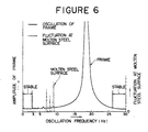
- the oscillation of the frame 2 and the fluctuations on the surface of the molten steel in the mold are induced according to the frequency of applied oscillation as shown in Figure 6.
- the frequency F(w) of natural vibration at the molten steel surface is expressed by
- the thickness or sectional width of the mold is 2 I
- the gravitational acceleration is g
- the degree is n.
- the oscillation at the molten steel surface is influenced by the dimensions of the mold and the frequency of the applied oscillation and take place at a point where the frequency of its natural vibration F( ⁇ ) coincides with the applied frequency N in an n-multiplied range.
- the fluctuation at the molten steel surface is taken on the vertical axis and the frequency of applied oscillation on the horizontal axis, there appear the waves as indicated by broken lines. Such waves occur when the frequency of the applied oscillation is in the range of 3 Hz to 26 Hz, and do not occur at the frequencies outside that range. A stable state can prevail at a frequency lower than 3 Hz or higher than 26 Hz.
- a range of high frequencies which can be used to oscillate the mold in a stable manner free of the influences of resonance of the oscillation system and fluctuations at the molten steel surface is hence higher than 26 Hz.
- the amplitude of oscillation of the oscillation system should be held at a minimum or at zero level if possible until its frequency exceeds the frequency of the natural oscillation so that resonance of the oscillation system is suppressed while the frequency of oscillation is raised to the required high frequency. Therefore, the oscillation which is applied to the oscillation system by the electro- hydraulic servo device 8 through the cylinder 1 is controlled solely with regard to its frequency in the initial stage of oscillation of the mold.
- the control circuit It is only after the frequency has been raised from zero to a required high level by the control circuit that the amplitude of the oscillation is raised from zero to a predetermined value, to start the application of oscillation to the oscillation system at a frequency higher than that of natural frequency.
- the oscillation to be applied to the oscillation system is controlled by the control circuit in two stages by raising the frequency in the first stage and increasing the amplitude in the next stage.
- the oscillation to be applied to the mold supporting frame 2 from the electro- hydraulic device 8 through the cylinder 1 is immediately raised to a required frequency, for instance, to 30 Hz at point t1 as shown in Figure 7(b) and thereafter kept at that frequency.
- the amplitude of the oscillation is held at zero at the time point t1, gradually increased from the time point t2 to reach a preset amplitude, for instance, an amplitude of 1.5 mm at the time point t3, kept at the amplitude of 1.5 mm until the time point t4, reduced from the time point t4 to become zero at the time point t5, and increased again at the time point t6 to reach 2.2 mm at the time point t7.
- the oscillation to be applied to the frame 2 is preferred to have a frequency 1.5 times greater than the frequency of its natural oscillation, and normally set at a frequency higher than 25 Hz, while the amplitude which is preferred to be as small as possible is normally set at a value smaller than 2 mm.
- the downward speed of the mold and the cast strand withdrawing speed are . determined in the same manner as in the conventional method ( Figure 1).
- the mold is oscillated by an electro-hydraulic servo device 8 which is controlled to start the oscillation of the mold at a preset frequency preferably higher than the natural frequency of the oscillation to a value in a range as determined by the ratio of the time length of a downward period of the mold movement to the time length in which the speed of the mold movement is higher than the casting speed in the downward period.
- the frequency of mold vibration is preset at a value approximately 1.5 times greater than the natural frequency of the frame.
- the objective of the invention can be achieved by very simple means, oscillating the mold at a frequency higher than that of the natural frequency of the frame to permit continuous casting of slabs and blooms which are free of oscillation defects and which require no defect-removing treatment prior to rolling.
- Steel sheets obtained from slabs which were produced according to the method of the present invention bore almost no defects and showed a yield of 99% in average.
- the method of the present invention permits the frequency and amplitude of the mold oscillation to be selected arbitrarily from a broad range in contrast to the conventional methods, so that it becomes possible to perform the mold oscillating operation in a simple and reliable manner in the continuous casting process.
- the cast strand can be effectively oscillated without causing the oscillation at a high frequency, and the amplitude of mold oscillation can be set at a small value which would not require an objectionably high rigidity of the frame and thus permit economical designing of the oscillation system.
- Figure 8 shows the results of test studying the amplitudes of oscillations of the frame 2 and the molten steel in the mold which were oscillated by the mold oscillator as shown in Figure 1, using a mold of 900 mm in width and 250 mm in thickness and an oscillating frame 2 with the natural frequency at 18 Hz.
- the frequency of oscillation is set at 6 Hz which is 1/3 of the natural frequency of the frame 2, there occurs an extremely large natural frequency as indicated by X.
- the frequency of oscillation is reduced from 4.5 Hz (1/4 of the natural frequency of the frame) to 3.6 Hz (1/5), the natural frequency of the frame 2 is reduced gradually although it is still at a high level.
- a frequency more than 6 times greater than that of the oscillation may be in the vicinity of the hexaploid frequency (i.e., in the vicinity of 18 Hz) to preclude the influences of resonance, and there is no necessity to use a frequency more than 10 times greater.
- Figures 9 and 10 show an embodiment employing an oscillating frame with a natural frequency of 18 Hz and adapted to apply oscillation thereto by an oscillator in a frequency range of 0 to 3 Hz.
- the free end portions of side portions 101a and 101b of an oscillating frame 101 are pivotably supported on a support frame 110 through a pivoting shaft 111 and connected with each other by a sub frame 101d.
- the transverse beam portion 101c of the oscillating frame 101 is connected at the lower center portion thereof to a rod of an oscillator 102 thereby to rock the side portions 1a and 1b up and down about the pivoting shaft 111.
- brackets 113 Projecting from the center portions of the side frames 101 a and 101 b are brackets 113 the upper ends of which are securely connected through support shafts 115 to the opposite sides of an outer mold frame provided with a mold 104.
- the mold can be oscillated up and down by operation of the oscillator 102.
- the oscillating frame 101 Since the oscillating frame 101 is designed to have a natural frequency six times greater than the frequency of oscillation of the oscillator 102, it will not interfere with a cast strand guide roll drive mechanism 120 which is provided beneath the side portions 101a a and 101b of the oscillating frame 101.
- the interference with the strand guide mechanism 115 occurs as indicated by a chain line in the figure when the natural frequency of the oscillating frame 101 is more than 110 times greater than the frequency of oscillation as in the conventional method.
- the oscillating frame is designed to have a rigidity more than 6 times greater than the frequency of oscillation, and an approximately 6 times greater natural frequency, it then becomes possible to reduce the weight of the oscillating frame as compared with the conventional counterpart with a 10 times greater natural frequency (e.g., from 20t at a frequency multiplied by 10 to 14.5t at a frequency multiplied by 6), permitting a more economical design for the oscillating frame. It also becomes possible to provide an oscillating frame of compact construction which requires a reduced space even in the case of an oscillator of a high frequency. Further, the preclusion of resonance of the oscillating frame and of rippling at that surface of molten steel bring about operational and other advantages.
- the detected amount of deviation is amplified at the control amplifier 214 and fed to another adding point 223 to detect its deviation from an output signal of an amplifier 222 which amplifies the position signal of the spool of a servo valve 216, which is produced by another differential transformer 221.
- the resulting deviation signal is fed to the servo amplifier 215, driving the cylinder 218 according to the output signal of the function generator 213 by the servo valve 216 to oscillate the oscillating frame 202 thereby to apply oscillation to the mold 204.
- the rate of oscillation defects on the continuously cast strand can be reduced by increasing the frequency of oscillation of the mold.
- the control circuit shown in Figure 11 if the frequency of the output of the function generator 213 is increased from about 1 Hz to about 30 Hz, the amplitude of oscillation of the oscillating frame 202 is increased abnormally at a frequency which coincides with the natural frequency of the oscillation system of the oscillating frame 202, for example, in the vicinity of 15 Hz. After that, the amplitude is attenuated, making it difficult to obtain an amplitude of a preset value in high frequency range of approximately 30 Hz. If the gains of the amplifier 214 and servo amplifier 215 are changed to make up for the above-mentioned attenuation in amplitude of the oscillating frame 202, adverse changes in the stable operating condition of the control system can occur.
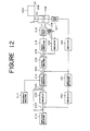
- FIG. 12 there is shown a control circuit according to the present invention, in which the component parts common to Figure 11 are designated by like reference numerals.
- denoted at 231 is an amplitude detector, at 232 an amplifier, at 233 an adding point, at 234 an amplifier, and at 235 another adding point.
- the amplitude detector 231 constitutes a circuit which converts the position signal of the cylinder 218 from the amplifier 219 into a signal indicative of the amplitude of the cylinder 218. This amplitude signal is fed to the adding point 233 after amplification at the amplifier 232.
- the adding point 233 constitutes a deviation detector which detects the amount of deviation s of the amplitude signal of the cylinder 218 amplified by the amplifier 232, from the signal of the preset amplitude selector 212.
- the deviation s is fed to an amplifier 234 operating with predetermined amplification K to produce an output signal Ks.
- the signal Ks and the signal of the preset amplitude from the amplitude selector 212 are fed to the adding point 235, which is constituted by an adder, and the output signal of the adding point 235 is fed to the function generator 213 as a fresh amplitude signal.
- the foregoing circuit arrangement can oscillate the cylinder 218 correctly at an amplitude conforming with the signal of a preset amplitude from the amplitude selector 212 in contrast to the conventional control circuit of Figure 11 in which the cylinder 218 is in some cases oscillated with an amplitude, for example, of 1.5 mm even when the amplitude selector 212 produces an output signal of a preset amplitude of 3 mm.
- the amplitude of 1.5 mm of the oscillation of the cylinder 218 is detected by the amplitude detector 231, and the detected value is fed to the amplifier 232 which supplies to the adding point 233 a signal corresponding to the amplitude of 1.5 mm.
- the signal of preset amplitude to be fed to the function generator 213 is increased from 3 mm to 4.5 mm in the case of the control circuit of Figure 11, and permits the cylinder 218 to oscillate with an amplitude of 3 mm. In this instance, no change occurs to the function to be transmitted through the control system downstream of the function generator 213 so that there is no possibility of disturbing the operational stability.
- the cylinder 218 can be oscillated at an amplitude which is preset by the amplitude selector 212, without changing the transfer function of the oscillation control system of the cylinder 218.
- the amplification rate K is determined according to the amplitude as preset by the amplitude selector 212.
- FIG. 13 there is shown a control circuit of a modified form which differs from the circuit of Figure 12 in that a digital signal processor is employed for correcting the amplitude signal to be produced by the amplitude selector 212.
- a digital signal processor is employed for correcting the amplitude signal to be produced by the amplitude selector 212.
- indicated at 241 is an A/D converter for converting the amplitude of oscillation of the cylinder 218 a digital signal, at 242 a microcomputer, and at 243 a D/A converter for producing an oscillation wave signal for the cylinder 218 according to the digital signal from the microcomputer 242.
- the microcomputer 242 is adapted to carry out the steps 201 to 207 of the flowchart shown in Figure 14 to control the amplitude of the oscillational wave signal of the D/A converter 243 in such a manner that the amplitude A of oscillation of the cylinder 218 conforms with the preset amplitude signal S from the amplitude selector 212.
- a * S it produces a signal of Ks+S as a fresh amplitude signal, thereby constantly maintaining the amplitude of oscillation of the cylinder 218 in comformity with the amplitude which has been preset by way of the amplitude selector 212.
- the mold oscillation control circuit according to the present invention is adapted to correct the value of the preset amplitude by seemingly increasing the preset value of amplitude when the amplitude of oscillation of the mold is smaller than the preset value, without. changing the transfer function of the control system, so that the mold can be oscillated in a sufficiently large amplitude by the control system even in a high frequency range in the vicinity of 30 Hz. Further, this can be attained simply by adding relatively simple components externally to the conventional mold oscillation control system.
Landscapes
- Engineering & Computer Science (AREA)
- Mechanical Engineering (AREA)
- Continuous Casting (AREA)
Description
- This invention relates in general to the production of continuously cast metal strands through a mold, and more particularly to a method of and an apparatus for continuously casting a strand by oscillating a mold by an electro-hydraulic or mechanical drive means according to the preamble of
claims 1 and 5 respectively. - In continuous casting, it is necessary to prevent seizure or breakout of the cast strand by reducing the friction between the mold and the cast strand. In this regard, it has been the general practice to resort to the so called mold oscillating system which reduces the friction between the mold and a cast strand by oscillating the mold up and down in the vertical direction during the casting operation. Generally, in casting operations using an oscillating mold, the mold is oscillated such that the maximum speed of the downward movement of the mold is greater than the strand withdrawing speed. More specifically, as shown in Figure 1 which is a diagram showing the relationship between the downward mold speed and the cast strand withdrawing speed the oscillation of the mold is set so that the ratio of the time tn in which the downward speed of the mold is greater than the strand withdrawing speed to the time tp of the downward mold movement (tnltpx100) is in the range of 60% to 80%. With regard to more specific conditions of oscillation, it has been the conventional practice to set the frequency of oscillation to 60-90 C/min and the amplitude of oscillation at 6-10 mm. However, under such conditions, positive and negative defective structures can occur at the roots of the oscillation mark, which can lead to fine cracks, in addition to the defects due to powder inclusion.
- The oscillation defects which occur at the roots of the oscillation mark mainly exist in the surface layer within a depth of 2 mm, so that, if a cast strand is rolled into a sheet without any prior treatment, the defects come out as an irregular pickling pattern and other surface defects, impairing the surface quality of the resulting steel sheet to a considerable degree. According to the conventional procedure, these defects are removed by a grinding operation at an intermediate stage which obviously increases costs and involves extra time. In this connection, Figure 2 shows the relationship between the rate (%) of occurrence of the oscillation defects of the cast strand and the frequency of oscillation in C/min. As shown in the figure, oscillation defects can be reduced by increasing the frequency of oscillation. However, the increase in frequency has to be limited to a certain level since at higher oscillation frequencies the so-called "sloshing", caused by surface oscillations of the molten steel, occurs as well as resonance of the oscillation system at its natural frequency.
- Reference is made in detail to the process and apparatus shown in US Patent Specification 3344847 forming the first part of
claims 1 and 5, respectively. - With due regard to the foregoing, the present invention has as its object the provision of a method of and an apparatus for continuous casting by the use of a mold oscillating system which can mitigate the problems mentioned.
- The present invention provides a method for continuous casting utilising an oscillating mould and an oscillator apparatus serving to oscillate the mould: said oscillator apparatus being driven in accordance with a preselected oscillation amplitude and frequency signal produced by a function generator; characterised in that
- a position signal of an oscillating part of said oscillator apparatus is converted into an amplitude signal;
- the amount of deviation of said amplitude signal is calculated from the value of said preselected amplitude signal; and,
- the amount of deviation is multiplied by a coefficient and added to said preselected amplitude signal to produce a new amplitude signal which is applied to said function generator.
- The present invention also provides a continuous casting apparatus comprising a mould oscillator apparatus adapted to oscillate a mould with a preselected amplitude and frequency, and
- a control circuit whereby said oscillator apparatus is driven according to a signal preselected amplitude and frequency control signal produced by the control circuit, said control circuit means comprising a function generator for producing the control signal of preselected amplitude and frequency; characterised by
- an amplitude detector for converting a position signal of an oscillating part of said oscillator apparatus to an amplitude signal; a deviation detector for calculating the amount of deviation of said amplitude signal from said preselected amplitude control signal;
- and an adder adapted to add the resulting signal to said preselected amplitude after multiplication by a coefficient and applying the resulting amplitude signal to said function generator as a new amplitude control signal.
- The above and other objects, features, aspects and advantages of the present invention will become apparent from the following description and the appended claims, taken in conjunction with the accompanying drawings which show, inter alia and by way of example only, some illustrative embodiments of the invention.
- In the accompanying drawings:
- Figure 1 is a diagram showing the relationship between the mold oscillating speed and the cast strand withdrawing speed and time;
- Figure 2 is a diagram showing the influence of the oscillation frequency on the rate of oscillation defects;
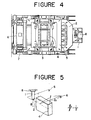
- Figures 3 and 4 are side view and plan view, respectively, of a casting machine employed for carrying out the continuous casting method according to the invention;
- Figure 5 is a schematic illustration explanatory of the construction of the casting machine of Figure 3;
- Figure 6 is a diagram showing the characteristic curves of oscillation of the frame and the molten steel surface in the mold of the casting machine of Figure 3;
- Figures 7(a) and 7(b) are diagrams showing the cast strand withdrawing speed in relation with the oscillation of the mold;
- Figure 8 is a Cambell diagram showing the relationship between the frequency of oscillation and the frequency of oscillation of the frame;
- Figures 9 and 10 are schematic plan and front views of another embodiment of the continuous casting machine according to the invention;
- Figure 11 is a block diagram of a conventional mold oscillation control circuit;
- Figure 12 is a block diagram of a mold oscillation control circuit according to the present invention;
- Figure 13 is a view similar to Figure 12 showing a mold oscillation control circuit of a modified form; and
- Figure 14 is a flowchart showing the steps of operation by the microcomputer employed in the circuit of Figure 13.
- Referring to the accompanying drawings and first to Figures 3 and 4, there is shown an essential part of a casting machine which is suitable for carrying out the method of continuous casting according to the present invention.
- As shown a
mold 4 is supported on a vibratory or oscillatingframe 2 with awater feed frame 5 provided on the lower outer periphery of themold 4. Theoscillatory frame 2 has the ends of its opposite side portions pivotally supported on astationary machine frame 7 atjoints 6. Theframe 2 has a center portion of a transverse member securely connected to cylinder 1 of anelectrohydraulic servo device 8 mounted on the base of theframe 7 on the other side of the machine. The oscillation system composed of theframe 2, including themold 4, is oscillated about thefulcrum points 6 relative to themachine frame 7 through an oscillation guide by the action of the cylinder 1. The drive of the electro-hydraulic servo device 8 is controlled by an electric control circuit, which will be described hereinafter. The control circuit is capable of separately controlling the frequency and amplitude of oscillation. - The above-mentioned oscillation system is schematically shown in Figure 5. In this case, the response magnification F(x) of the frame in such a system is expressed by

frame 2 and the fluctuations on the surface of the molten steel in the mold are induced according to the frequency of applied oscillation as shown in Figure 6. When the applied frequency is w and the resonance frequency of the oscillation system of theframe 2 is wo, its oscillation frequency ratio F(r) is expressed by

- In order to oscillate the oscillation system at a frequency higher than its natural frequency, the amplitude of oscillation of the oscillation system should be held at a minimum or at zero level if possible until its frequency exceeds the frequency of the natural oscillation so that resonance of the oscillation system is suppressed while the frequency of oscillation is raised to the required high frequency. Therefore, the oscillation which is applied to the oscillation system by the electro-
hydraulic servo device 8 through the cylinder 1 is controlled solely with regard to its frequency in the initial stage of oscillation of the mold. It is only after the frequency has been raised from zero to a required high level by the control circuit that the amplitude of the oscillation is raised from zero to a predetermined value, to start the application of oscillation to the oscillation system at a frequency higher than that of natural frequency. In other words, the oscillation to be applied to the oscillation system is controlled by the control circuit in two stages by raising the frequency in the first stage and increasing the amplitude in the next stage. Therefore, for example, in a case where the cast strand withdrawing speed is scheduled to be zero at a casting start point t1, accelerated from a withdrawal start point t2 to a point t3 at which a preset withdrawing speed is reached, kept at the preset speed until a speed-down instruction point t4, lowered to zero from the point t4 to a head solidifying point t5, and accelerated again from a re-withdrawing point t6 to a point t7 at which a cast strand is passed through the mold, as shown in Figure 7(a), the oscillation to be applied to themold supporting frame 2 from the electro-hydraulic device 8 through the cylinder 1 is immediately raised to a required frequency, for instance, to 30 Hz at point t1 as shown in Figure 7(b) and thereafter kept at that frequency. On the other hand, the amplitude of the oscillation is held at zero at the time point t1, gradually increased from the time point t2 to reach a preset amplitude, for instance, an amplitude of 1.5 mm at the time point t3, kept at the amplitude of 1.5 mm until the time point t4, reduced from the time point t4 to become zero at the time point t5, and increased again at the time point t6 to reach 2.2 mm at the time point t7. The oscillation to be applied to theframe 2 is preferred to have a frequency 1.5 times greater than the frequency of its natural oscillation, and normally set at a frequency higher than 25 Hz, while the amplitude which is preferred to be as small as possible is normally set at a value smaller than 2 mm. The downward speed of the mold and the cast strand withdrawing speed are . determined in the same manner as in the conventional method (Figure 1). - As is clear from the foregoing, in the mold oscillating system for continuous casting according to the present invention the mold is oscillated by an electro-
hydraulic servo device 8 which is controlled to start the oscillation of the mold at a preset frequency preferably higher than the natural frequency of the oscillation to a value in a range as determined by the ratio of the time length of a downward period of the mold movement to the time length in which the speed of the mold movement is higher than the casting speed in the downward period. Preferably, the frequency of mold vibration is preset at a value approximately 1.5 times greater than the natural frequency of the frame. Thus, the objective of the invention can be achieved by very simple means, oscillating the mold at a frequency higher than that of the natural frequency of the frame to permit continuous casting of slabs and blooms which are free of oscillation defects and which require no defect-removing treatment prior to rolling. Steel sheets obtained from slabs which were produced according to the method of the present invention bore almost no defects and showed a yield of 99% in average. Further, as mentioned hereinbefore, the method of the present invention permits the frequency and amplitude of the mold oscillation to be selected arbitrarily from a broad range in contrast to the conventional methods, so that it becomes possible to perform the mold oscillating operation in a simple and reliable manner in the continuous casting process. The cast strand can be effectively oscillated without causing the oscillation at a high frequency, and the amplitude of mold oscillation can be set at a small value which would not require an objectionably high rigidity of the frame and thus permit economical designing of the oscillation system. - Figure 8 shows the results of test studying the amplitudes of oscillations of the
frame 2 and the molten steel in the mold which were oscillated by the mold oscillator as shown in Figure 1, using a mold of 900 mm in width and 250 mm in thickness and anoscillating frame 2 with the natural frequency at 18 Hz. As is clear from Figure 8, when the frequency of oscillation is set at 6 Hz which is 1/3 of the natural frequency of theframe 2, there occurs an extremely large natural frequency as indicated by X. As the frequency of oscillation is reduced from 4.5 Hz (1/4 of the natural frequency of the frame) to 3.6 Hz (1/5), the natural frequency of theframe 2 is reduced gradually although it is still at a high level. If the frequency of oscillation is lowered to 3 Hz which is 1/6 of the natural oscillation, there occurs only an extremely small oscillation as indicated by Y. With a certain frequency of oscillation, no resonance occurs to theframe 2. On the other hand, the fluctuations (sloshing) of the surface of molten steel in the mold which is governed by the sectional dimensions of the mold and the frequency of oscillation take place at a range where the frequency of natural oscillation of the frame coincides with the frequency of oscillation in a particular range, namely, at a point where the former is n-times (1/ 2, 1/3) greater than the latter. - The foregoing test results reveal that, in order to preclude the resonance of the oscillating frame, the oscillating frame should have a natural frequency mo.re than 6 times greater than the frequency of oscillation to be applied thereto since otherwise a larger resonance would occur to the frame, causing irregular vibrations to the mold and rippling at the surface of the molten steel. Consequently, in a case where the oscillation is to be applied at a frequency range of approximately 0 to 3 Hz and at a frequency lower than that of the intrinsic vibration of the frame, it suffices to design the frame to have a natural frequency at least 6 times higher, namely, at a frequency of at least 3x6=18 Hz. In the case where a frequency more than 6 times greater than that of the oscillation is employed, it may be in the vicinity of the hexaploid frequency (i.e., in the vicinity of 18 Hz) to preclude the influences of resonance, and there is no necessity to use a frequency more than 10 times greater.
- Figures 9 and 10 show an embodiment employing an oscillating frame with a natural frequency of 18 Hz and adapted to apply oscillation thereto by an oscillator in a frequency range of 0 to 3 Hz. In this embodiment, the free end portions of side portions 101a and 101b of an
oscillating frame 101 are pivotably supported on asupport frame 110 through a pivotingshaft 111 and connected with each other by a sub frame 101d. The transverse beam portion 101c of theoscillating frame 101 is connected at the lower center portion thereof to a rod of anoscillator 102 thereby to rock the side portions 1a and 1b up and down about the pivotingshaft 111. Projecting from the center portions of the side frames 101 a and 101 b arebrackets 113 the upper ends of which are securely connected throughsupport shafts 115 to the opposite sides of an outer mold frame provided with amold 104. Thus, the mold can be oscillated up and down by operation of theoscillator 102. - Since the
oscillating frame 101 is designed to have a natural frequency six times greater than the frequency of oscillation of theoscillator 102, it will not interfere with a cast strand guideroll drive mechanism 120 which is provided beneath the side portions 101a a and 101b of theoscillating frame 101. The interference with thestrand guide mechanism 115 occurs as indicated by a chain line in the figure when the natural frequency of theoscillating frame 101 is more than 110 times greater than the frequency of oscillation as in the conventional method. - Thus, in the foregoing embodiment, the oscillating frame is designed to have a rigidity more than 6 times greater than the frequency of oscillation, and an approximately 6 times greater natural frequency, it then becomes possible to reduce the weight of the oscillating frame as compared with the conventional counterpart with a 10 times greater natural frequency (e.g., from 20t at a frequency multiplied by 10 to 14.5t at a frequency multiplied by 6), permitting a more economical design for the oscillating frame. It also becomes possible to provide an oscillating frame of compact construction which requires a reduced space even in the case of an oscillator of a high frequency. Further, the preclusion of resonance of the oscillating frame and of rippling at that surface of molten steel bring about operational and other advantages.
- In controlling the electro-
hydraulic servo device 8, it has been the conventional practice to employ a control circuit as shown in Figure 11, in which indicated at 211 is a frequency selector, at 212 an amplitude selector, at 213 a function generator, at 214 a control amplifier, and at 215 a servo amplifier. A position signal of the cylinder of theelectrohydraulic servo 208, which is produced by adifferential transformer 217, is amplified atamplifier 219 and fed to an addingpoint 220 to detect its deviation from the output signal of thefunction generator 213. The detected amount of deviation is amplified at thecontrol amplifier 214 and fed to another addingpoint 223 to detect its deviation from an output signal of anamplifier 222 which amplifies the position signal of the spool of aservo valve 216, which is produced by anotherdifferential transformer 221. The resulting deviation signal is fed to theservo amplifier 215, driving thecylinder 218 according to the output signal of thefunction generator 213 by theservo valve 216 to oscillate theoscillating frame 202 thereby to apply oscillation to themold 204. - As mentioned hereinbefore, the rate of oscillation defects on the continuously cast strand can be reduced by increasing the frequency of oscillation of the mold. However, with the control circuit shown in Figure 11, if the frequency of the output of the
function generator 213 is increased from about 1 Hz to about 30 Hz, the amplitude of oscillation of theoscillating frame 202 is increased abnormally at a frequency which coincides with the natural frequency of the oscillation system of theoscillating frame 202, for example, in the vicinity of 15 Hz. After that, the amplitude is attenuated, making it difficult to obtain an amplitude of a preset value in high frequency range of approximately 30 Hz. If the gains of theamplifier 214 andservo amplifier 215 are changed to make up for the above-mentioned attenuation in amplitude of theoscillating frame 202, adverse changes in the stable operating condition of the control system can occur. - Referring to Figure 12, there is shown a control circuit according to the present invention, in which the component parts common to Figure 11 are designated by like reference numerals. In Figure 12, denoted at 231 is an amplitude detector, at 232 an amplifier, at 233 an adding point, at 234 an amplifier, and at 235 another adding point. The
amplitude detector 231 constitutes a circuit which converts the position signal of thecylinder 218 from theamplifier 219 into a signal indicative of the amplitude of thecylinder 218. This amplitude signal is fed to the addingpoint 233 after amplification at theamplifier 232. - The adding
point 233 constitutes a deviation detector which detects the amount of deviation s of the amplitude signal of thecylinder 218 amplified by theamplifier 232, from the signal of thepreset amplitude selector 212. The deviation s is fed to anamplifier 234 operating with predetermined amplification K to produce an output signal Ks. The signal Ks and the signal of the preset amplitude from theamplitude selector 212 are fed to the addingpoint 235, which is constituted by an adder, and the output signal of the addingpoint 235 is fed to thefunction generator 213 as a fresh amplitude signal. - The foregoing circuit arrangement can oscillate the
cylinder 218 correctly at an amplitude conforming with the signal of a preset amplitude from theamplitude selector 212 in contrast to the conventional control circuit of Figure 11 in which thecylinder 218 is in some cases oscillated with an amplitude, for example, of 1.5 mm even when theamplitude selector 212 produces an output signal of a preset amplitude of 3 mm. More specifically, in the control circuit of Figure 12, the amplitude of 1.5 mm of the oscillation of thecylinder 218 is detected by theamplitude detector 231, and the detected value is fed to theamplifier 232 which supplies to the adding point 233 a signal corresponding to the amplitude of 1.5 mm. At the addingpoint 233, the signal is added to the amplitude signal of 3 mm from theamplitude selector 212 to produce a signal corresponding to the value of (3-1.5)=1.5 mm. This signal is amplified by theamplifier 234 which, if its amplification rate K=1, produces and supplies to the adding point 235 a signal corresponding to 1.5 mm. - At the adding
point 235, the signal of 1.5 mm from theamplifier 234 is added to the signal of 3 mm of the preset amplitude from theamplitude selector 212 to feed a fresh amplitude signal of (1.5+3)=4.5 mm to thefunction generator 213. This means that the signal of preset amplitude to be fed to thefunction generator 213 is increased from 3 mm to 4.5 mm in the case of the control circuit of Figure 11, and permits thecylinder 218 to oscillate with an amplitude of 3 mm. In this instance, no change occurs to the function to be transmitted through the control system downstream of thefunction generator 213 so that there is no possibility of disturbing the operational stability. - When the
cylinder 218 is oscillated at the amplitude of 3 mm which is equivalent to the signal of the preset amplitude from theamplitude selector 212, the deviation becomes=0 so that the addingpoint 235 supplies to the function generator the signal of the preset amplitude from theamplitude selector 212 as it is and accordingly thecylinder 218 is oscillated in the amplitude conforming with the preset amplitude. - By controlling the amplitude signal to be fed to the
function generator 213 according to the amplitude of vibration of thecylinder 218 in this manner, thecylinder 218 can be oscillated at an amplitude which is preset by theamplitude selector 212, without changing the transfer function of the oscillation control system of thecylinder 218. In the embodiment of Figure 12, the amplification rate K is determined according to the amplitude as preset by theamplitude selector 212. - Referring to Figure 13, there is shown a control circuit of a modified form which differs from the circuit of Figure 12 in that a digital signal processor is employed for correcting the amplitude signal to be produced by the
amplitude selector 212. In the circuit diagram of Figure 12, indicated at 241 is an A/D converter for converting the amplitude of oscillation of the cylinder 218 a digital signal, at 242 a microcomputer, and at 243 a D/A converter for producing an oscillation wave signal for thecylinder 218 according to the digital signal from themicrocomputer 242. - The
microcomputer 242 is adapted to carry out the steps 201 to 207 of the flowchart shown in Figure 14 to control the amplitude of the oscillational wave signal of the D/A converter 243 in such a manner that the amplitude A of oscillation of thecylinder 218 conforms with the preset amplitude signal S from theamplitude selector 212. In this instance, themicrocomputer 242 judges whether or not A=S and, if A=S, sends out the signal S as a fresh amplitude signal. If A * S, it produces a signal of Ks+S as a fresh amplitude signal, thereby constantly maintaining the amplitude of oscillation of thecylinder 218 in comformity with the amplitude which has been preset by way of theamplitude selector 212. - As clear from the foregoing description, the mold oscillation control circuit according to the present invention is adapted to correct the value of the preset amplitude by seemingly increasing the preset value of amplitude when the amplitude of oscillation of the mold is smaller than the preset value, without. changing the transfer function of the control system, so that the mold can be oscillated in a sufficiently large amplitude by the control system even in a high frequency range in the vicinity of 30 Hz. Further, this can be attained simply by adding relatively simple components externally to the conventional mold oscillation control system.
- Although the invention has been described in terms of specific embodiments, it is to be understood that other forms of invention may be readily adapted within the scope of the invention as defined in the appended claims.
Claims (9)
characterised in that:
Applications Claiming Priority (4)
| Application Number | Priority Date | Filing Date | Title |
|---|---|---|---|
| JP37169/83 | 1983-03-07 | ||
| JP3716983A JPS59163055A (en) | 1983-03-07 | 1983-03-07 | Oscillator for casting mold in continuous casting installation |
| JP13496283A JPS6027461A (en) | 1983-07-22 | 1983-07-22 | Method and device for controlling casting mold vibrator |
| JP134962/83 | 1983-07-22 |
Publications (2)
| Publication Number | Publication Date |
|---|---|
| EP0121622A1 EP0121622A1 (en) | 1984-10-17 |
| EP0121622B1 true EP0121622B1 (en) | 1988-02-24 |
Family
ID=26376261
Family Applications (1)
| Application Number | Title | Priority Date | Filing Date |
|---|---|---|---|
| EP83304972A Expired EP0121622B1 (en) | 1983-03-07 | 1983-08-26 | Method of and apparatus for continuous casting by the use of mold oscillating system |
Country Status (6)
| Country | Link |
|---|---|
| US (1) | US4577277A (en) |
| EP (1) | EP0121622B1 (en) |
| KR (1) | KR870002068B1 (en) |
| AU (1) | AU544310B2 (en) |
| CA (1) | CA1198570A (en) |
| DE (1) | DE3375718D1 (en) |
Cited By (3)
| Publication number | Priority date | Publication date | Assignee | Title |
|---|---|---|---|---|
| EP0570935A1 (en) * | 1992-05-21 | 1993-11-24 | Kawasaki Steel Corporation | Control device for controlling mold oscillation in a continuous casting machine |
| WO1998048960A1 (en) * | 1997-04-26 | 1998-11-05 | Sms Schloemann-Siemag Aktiengesellschaft | Method for swaying a continuous casting mold |
| WO2000030783A1 (en) * | 1998-11-25 | 2000-06-02 | Sms Schloemann-Siemag Aktiengesellschaft | Method for oscillating a continuous-casting mould by means of variable oscillation parameters |
Families Citing this family (11)
| Publication number | Priority date | Publication date | Assignee | Title |
|---|---|---|---|---|
| US5219029A (en) * | 1992-03-09 | 1993-06-15 | Gunther Behrends | Oscillator for continuous casting mold |
| TW274529B (en) * | 1993-10-21 | 1996-04-21 | Hitachi Shipbuilding Eng Co | |
| US5911268A (en) * | 1997-10-16 | 1999-06-15 | Custom Systems, Inc. | Oscillating mold table assembly |
| DE19814222A1 (en) * | 1998-03-31 | 1999-10-07 | Schloemann Siemag Ag | Process for continuous casting and finish rolling of a casting strand within a specified finished width tolerance |
| DE19845357A1 (en) * | 1998-10-02 | 2000-04-06 | Schloemann Siemag Ag | Method and device for the continuous control of the basic setting and oscillation parameters of a continuous casting mold |
| US20040177942A1 (en) * | 2001-01-12 | 2004-09-16 | Mason Douglas P. | Method and apparatus for vibration casting of vehicle wheels |
| DE102004058356A1 (en) * | 2004-12-03 | 2006-06-14 | Sms Demag Ag | Control and / or regulating device for a continuous casting mold carrying a lifting table of a continuous casting apparatus for liquid metals, in particular for liquid steel material |
| DE102008006189A1 (en) * | 2008-01-26 | 2009-07-30 | Sms Demag Ag | Device and method for regulating mold oscillations |
| CN102784896B (en) * | 2012-08-07 | 2014-07-02 | 中国重型机械研究院有限公司 | Mold oscillation synchronous control method |
| CN103894573B (en) * | 2014-03-20 | 2016-05-25 | 攀钢集团攀枝花钢钒有限公司 | Reduce the control method of conticaster bleed-out |
| CN107321948B (en) * | 2017-06-13 | 2019-05-24 | 燕山大学 | A kind of fault tolerant control method and device of the continuous cast mold non-sinusoidal oscillation of servo motor driving |
Family Cites Families (9)
| Publication number | Priority date | Publication date | Assignee | Title |
|---|---|---|---|---|
| US3523571A (en) * | 1967-03-01 | 1970-08-11 | Vitaly Maximovich Niskovskikh | Mold joggler for continuous casting |
| US3664409A (en) * | 1969-08-08 | 1972-05-23 | Kolomeitsev Adolf P | Mold rocking mechanism in a continuous metal casting plant |
| US3700024A (en) * | 1969-10-16 | 1972-10-24 | Concast Ag | Method of continuously casting steel billets |
| US3638714A (en) * | 1970-08-14 | 1972-02-01 | Koppers Co Inc | Method and apparatus for oscillating a continuous casting mold |
| US4237962A (en) * | 1978-08-11 | 1980-12-09 | Vandenhoeck J Paul | Self-cleaning heat exchanger |
| DE3062086D1 (en) * | 1979-12-19 | 1983-03-24 | Concast Holding Ag | Device for oscillating a continuous casting mould |
| SE452122B (en) * | 1980-04-04 | 1987-11-16 | Nippon Steel Corp | PROCEDURE FOR CONTINUOUS CASTING OF STEEL PLATINES FREE OF SURFACE |
| EP0041196A3 (en) * | 1980-05-30 | 1982-01-13 | Concast Holding Ag | Method and arrangement for oscillating a continuous casting mould |
| DE3261543D1 (en) * | 1981-08-10 | 1985-01-24 | Fives Cail Babcock | Driving and guiding mechanism for the oscillations of a continuous casting mould |
-
1983
- 1983-08-24 US US06/525,896 patent/US4577277A/en not_active Expired - Fee Related
- 1983-08-26 EP EP83304972A patent/EP0121622B1/en not_active Expired
- 1983-08-26 DE DE8383304972T patent/DE3375718D1/en not_active Expired
- 1983-08-27 KR KR1019830004011A patent/KR870002068B1/en not_active Expired
- 1983-08-29 CA CA000435571A patent/CA1198570A/en not_active Expired
- 1983-08-31 AU AU18565/83A patent/AU544310B2/en not_active Ceased
Cited By (6)
| Publication number | Priority date | Publication date | Assignee | Title |
|---|---|---|---|---|
| EP0570935A1 (en) * | 1992-05-21 | 1993-11-24 | Kawasaki Steel Corporation | Control device for controlling mold oscillation in a continuous casting machine |
| US5350005A (en) * | 1992-05-21 | 1994-09-27 | Kawasaki Steel Corporation | Control device for controlling mold oscillation in a continuous casting machine |
| WO1998048960A1 (en) * | 1997-04-26 | 1998-11-05 | Sms Schloemann-Siemag Aktiengesellschaft | Method for swaying a continuous casting mold |
| CN1072049C (en) * | 1997-04-26 | 2001-10-03 | Sms舒路曼-斯玛公司 | Method for swaying continuous casting mold |
| US6363998B1 (en) * | 1997-04-26 | 2002-04-02 | Sms Schloemann-Siemag Aktiengesellschaft | Method for swaying a continuous casting mold |
| WO2000030783A1 (en) * | 1998-11-25 | 2000-06-02 | Sms Schloemann-Siemag Aktiengesellschaft | Method for oscillating a continuous-casting mould by means of variable oscillation parameters |
Also Published As
| Publication number | Publication date |
|---|---|
| AU1856583A (en) | 1984-09-13 |
| US4577277A (en) | 1986-03-18 |
| EP0121622A1 (en) | 1984-10-17 |
| CA1198570A (en) | 1985-12-31 |
| KR840008433A (en) | 1984-12-15 |
| DE3375718D1 (en) | 1988-03-31 |
| AU544310B2 (en) | 1985-05-23 |
| KR870002068B1 (en) | 1987-12-03 |
Similar Documents
| Publication | Publication Date | Title |
|---|---|---|
| US4577277A (en) | Method and apparatus of continuous casting by the use of mold oscillating system | |
| US4883114A (en) | Oscillation method and apparatus for a continuous casting mold | |
| EP0372506B1 (en) | Method for oscillation of mold of vertical continuous caster | |
| EP0649692A1 (en) | Mold vibrating apparatus in continuous casting equipment | |
| US5390726A (en) | Process for producing thin metallic strip by continuous casting | |
| GB2108878A (en) | Vibration of a continuous casting machine mould | |
| US9174273B2 (en) | Method of and apparatus for controlling molten metal surface in mold of continuous-casting machine and continuous-casting machine including the apparatus | |
| KR200189484Y1 (en) | Nonlinear robust control device for mould oscillator | |
| JPH08150454A (en) | Mold vibration method during continuous casting of austenitic stainless steel. | |
| JPH05177310A (en) | Continuous casting mold and its short side shape control method | |
| JP2002059249A (en) | Level control method and level control device for continuous casting machine | |
| JP3651447B2 (en) | Operation method of continuous casting machine | |
| JPS58199645A (en) | Oscillating method of mold for continuous casting | |
| JP2002248555A (en) | Level control method and level control device for continuous casting machine | |
| SU1407661A1 (en) | Method of continuous casting of billets | |
| JPS6027461A (en) | Method and device for controlling casting mold vibrator | |
| JP2913114B2 (en) | Method of expanding mold width during continuous casting | |
| ATE139717T1 (en) | CONTINUOUS CASTING METHOD | |
| JP2885824B2 (en) | Metal continuous casting method | |
| JPH04274855A (en) | Molten metal surface level measuring method for continuous casting mold | |
| JPH0356823B2 (en) | ||
| JPS61147954A (en) | Mold oscillating method in continuous casting | |
| MXPA01005160A (en) | Method for oscillating a continuous-casting mould by means of variable oscillation parameters. | |
| JPH07236957A (en) | Mold vibration device in continuous casting equipment | |
| JPH038541A (en) | Apparatus for continuously casting strip |
Legal Events
| Date | Code | Title | Description |
|---|---|---|---|
| PUAI | Public reference made under article 153(3) epc to a published international application that has entered the european phase |
Free format text: ORIGINAL CODE: 0009012 |
|
| 17P | Request for examination filed |
Effective date: 19830908 |
|
| AK | Designated contracting states |
Designated state(s): DE FR GB IT |
|
| GRAA | (expected) grant |
Free format text: ORIGINAL CODE: 0009210 |
|
| AK | Designated contracting states |
Kind code of ref document: B1 Designated state(s): DE FR GB IT |
|
| ITF | It: translation for a ep patent filed | ||
| REF | Corresponds to: |
Ref document number: 3375718 Country of ref document: DE Date of ref document: 19880331 |
|
| ET | Fr: translation filed | ||
| PLBE | No opposition filed within time limit |
Free format text: ORIGINAL CODE: 0009261 |
|
| STAA | Information on the status of an ep patent application or granted ep patent |
Free format text: STATUS: NO OPPOSITION FILED WITHIN TIME LIMIT |
|
| 26N | No opposition filed | ||
| ITTA | It: last paid annual fee | ||
| PGFP | Annual fee paid to national office [announced via postgrant information from national office to epo] |
Ref country code: FR Payment date: 19960809 Year of fee payment: 14 |
|
| PGFP | Annual fee paid to national office [announced via postgrant information from national office to epo] |
Ref country code: GB Payment date: 19960819 Year of fee payment: 14 |
|
| PGFP | Annual fee paid to national office [announced via postgrant information from national office to epo] |
Ref country code: DE Payment date: 19960830 Year of fee payment: 14 |
|
| PG25 | Lapsed in a contracting state [announced via postgrant information from national office to epo] |
Ref country code: GB Free format text: LAPSE BECAUSE OF NON-PAYMENT OF DUE FEES Effective date: 19970826 |
|
| GBPC | Gb: european patent ceased through non-payment of renewal fee |
Effective date: 19970826 |
|
| PG25 | Lapsed in a contracting state [announced via postgrant information from national office to epo] |
Ref country code: FR Free format text: LAPSE BECAUSE OF NON-PAYMENT OF DUE FEES Effective date: 19980430 |
|
| PG25 | Lapsed in a contracting state [announced via postgrant information from national office to epo] |
Ref country code: DE Free format text: LAPSE BECAUSE OF NON-PAYMENT OF DUE FEES Effective date: 19980501 |
|
| REG | Reference to a national code |
Ref country code: FR Ref legal event code: ST |