EP0121370B1 - Apparatus for monitoring particulate matter - Google Patents
Apparatus for monitoring particulate matter Download PDFInfo
- Publication number
- EP0121370B1 EP0121370B1 EP84301833A EP84301833A EP0121370B1 EP 0121370 B1 EP0121370 B1 EP 0121370B1 EP 84301833 A EP84301833 A EP 84301833A EP 84301833 A EP84301833 A EP 84301833A EP 0121370 B1 EP0121370 B1 EP 0121370B1
- Authority
- EP
- European Patent Office
- Prior art keywords
- filter
- fluid
- filter material
- material layer
- pipe portion
- Prior art date
- Legal status (The legal status is an assumption and is not a legal conclusion. Google has not performed a legal analysis and makes no representation as to the accuracy of the status listed.)
- Expired
Links
- 239000013618 particulate matter Substances 0.000 title claims description 14
- 238000012544 monitoring process Methods 0.000 title claims description 11
- 239000012530 fluid Substances 0.000 claims description 31
- 239000000463 material Substances 0.000 claims description 22
- 238000009825 accumulation Methods 0.000 claims description 7
- 238000007789 sealing Methods 0.000 claims 2
- 239000011236 particulate material Substances 0.000 description 6
- 229920002799 BoPET Polymers 0.000 description 5
- 239000005041 Mylar™ Substances 0.000 description 5
- 230000006835 compression Effects 0.000 description 4
- 238000007906 compression Methods 0.000 description 4
- 230000001050 lubricating effect Effects 0.000 description 4
- 238000005070 sampling Methods 0.000 description 3
- 238000001914 filtration Methods 0.000 description 2
- 238000005461 lubrication Methods 0.000 description 2
- 239000002184 metal Substances 0.000 description 2
- 238000002441 X-ray diffraction Methods 0.000 description 1
- 230000002159 abnormal effect Effects 0.000 description 1
- 239000000853 adhesive Substances 0.000 description 1
- 230000001070 adhesive effect Effects 0.000 description 1
- 238000004458 analytical method Methods 0.000 description 1
- 238000002485 combustion reaction Methods 0.000 description 1
- 230000001186 cumulative effect Effects 0.000 description 1
- 230000007613 environmental effect Effects 0.000 description 1
- 238000011156 evaluation Methods 0.000 description 1
- 238000009434 installation Methods 0.000 description 1
- 239000007788 liquid Substances 0.000 description 1
- 230000007774 longterm Effects 0.000 description 1
- 239000000314 lubricant Substances 0.000 description 1
- 230000007257 malfunction Effects 0.000 description 1
- 238000004519 manufacturing process Methods 0.000 description 1
- 239000012528 membrane Substances 0.000 description 1
- 230000000737 periodic effect Effects 0.000 description 1
- 229920000515 polycarbonate Polymers 0.000 description 1
- 239000004417 polycarbonate Substances 0.000 description 1
- 239000011148 porous material Substances 0.000 description 1
- 238000000926 separation method Methods 0.000 description 1
- 239000000126 substance Substances 0.000 description 1
- 230000009897 systematic effect Effects 0.000 description 1
Images


Classifications
-
- G—PHYSICS
- G01—MEASURING; TESTING
- G01N—INVESTIGATING OR ANALYSING MATERIALS BY DETERMINING THEIR CHEMICAL OR PHYSICAL PROPERTIES
- G01N15/00—Investigating characteristics of particles; Investigating permeability, pore-volume or surface-area of porous materials
- G01N15/06—Investigating concentration of particle suspensions
- G01N15/0606—Investigating concentration of particle suspensions by collecting particles on a support
- G01N15/0618—Investigating concentration of particle suspensions by collecting particles on a support of the filter type
Definitions
- This invention relates to apparatus for monitoring particulate matter.
- particulate matter debris within a fluid can in many engineering situations create problems. For example, if a lubricating fluid or oil is contaminated to a sufficient level by particulate matter it may not continue to act as a lubricant. Alternatively, the increase in debris in the fluid can produce malfunction of a device in which the fluid is used, for example air used in a combustion engine. Consequently, it can be useful to know when an unacceptable level of particulate matter is attained or approached.
- an apparatus for monitoring particulate matter in a fluid comprising means defining a path for the fluid: filter means disposed across the fluid path: transfer means for transferring the fluid through the filter means at a constant flow rate: pressure sensing means arranged to sense the fluid pressure difference across the filter means and produce a signal indicative of said pressure difference: and processing means to which said signal is supplied and operative to provide an indication of accumulation of particulate matter in the filter means.
- the filter means is constituted by a pervious material member, such as a woven metal mesh member, which must be removed from the apparatus when the accumulation of particulate matter therein reaches a certain level, it being necessary to stop the apparatus while the member is changed.
- US-A-3678881 there is disclosed an apparatus comprising filter means: means for transferring fluid through the filter means at a constant flow rate: and pressure sensing means arranged to sense the fluid pressure difference across the filter means and to produce a pressure signal indicative of the magnitude of the pressure difference.
- the filter means is constituted by a metal mesh member which must be removed and replaced when a certain level of accumulation of particulate matter therein is reached.
- apparatus for monitoring particulate matter in a fluid comprising means defining a path for the fluid: filter means disposed across the fluid path: transfer means for transferring the fluid through the filter means at a constant flow rate: pressure sensing means arranged to sense the fluid pressure difference across the filter means and produce a signal indicative of said pressure difference: and processing means to which said signal is supplied and operative to provide an indication of accumulation of particulate matter in the filter means, characterised in that the filter means comprises a filter medium in the form of an elongate strip formed as a separable laminate of a filter material layer and a backing strip layer, and a transport arrangement comprising two rotatable spools having the filter medium extending between them with means to separate the backing strip from the filter material over a short distance between the spools, the transfer means being arranged to transfer the fluid through the filter material where separated from the backing strip, and the transport arrangement being actuable to move the filter medium between the spools thereby to present a new portion of filter material for
- the apparatus of this invention has the advantages that a new portion of filter material can easily be positioned in the fluid path when necessary, and that very thin filter material can be used since the filter material is supported by the backing strip at all positions other than over a small distance where the filter material alone is in the fluid path.
- the used filter material constitutes a record of the accumulation of particulate material at the filter medium, and by systematic X-ray analysis of this record cumulative curves for the various components of the particulate material filtered out of the fluid over the period of time covered by the record, can be plotted, there possibly being some correlation between such curves and the source of the particulate material.
- JP-A-55-35250 An apparatus using a filter medium in strip form wound between two spools is disclosed in JP-A-55-35250.
- the filter medium is simply a layer of filter material, there being no backing strip therefor, as used in the apparatus of the present invention.
- the processing means includes means to store values indicated by the signals received from the pressure sensing means: means to compare the value indicated by the signal last received with a value indicated by a signal received a predetermined time earlier and to derive a difference value therefrom: and means to evaluate the quotient of said predetermined time in said difference value.
- Such processing means can evalulate the change of the pressure difference across the filter means, which evaluation can then be used as an on-line monitoring parameter for particulate material generation. In this way short-term abnormal increases in particulate material can be detected and also long-term trends in the build-up of particulate material can be observed.
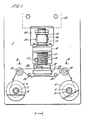
- an apparatus for monitoring particulate matter in a liquid comprises a plate 1 having two axle shafts 2 and 3 provided on a lower portion of one side thereof.
- the shafts receive spools 4 and 5 respectively, which are held thereon by clips 6 which are a friction fit onto the axle stub extending through the spools.
- Bearings 34 are provided on the axles to allow rotation of spools received thereon. Any other suitable means for retaining the spools on the axles can be employed.
- a fluid inlet is provided on the plate in equal spaced relation from each axle, although this is not essential to the working of the apparatus.
- the arrangement comprises a horizontal semi-circular disc 7 having a flange 8 located on the diametrical edge thereof, the remaining edges being bevelled.
- a cup shaped depression 9 is provided in the upper surface of the disc and an inlet pipe 10 is bored into the side of the plate from the diametrical edge to connect to the base of the depression.
- the plate includes an aperture 11 through which a connection pipe 14 is inserted which has a screw thread 13 to screw into the inlet pipe 10.
- a lock nut 12 provided on the connection pipe end contacts the back surface of the plate as the connection pipe is screwed into the inlet pipe. Consequently, the plate is sandwiched between the lock nut and and flange 8 so that the inlet arrangement is clamped to the same side of the plate as the axles.
- a fluid outlet arrangement comprises a vertical pipe 15, slidably located through an eye of a support arrangement 16 connected to the plate by screws 17.
- the lower end of the vertical pipe includes a flange 18 and has a compression spring 19 located to encircle the pipe between the flange and the eye to resiliently bias the pipe downwards onto contact with the upper surface of the disc 7.
- the vertical pipe opens out at its lower end to a depression 21 substantially the same cross section and directly above the cup-shaped depression 9 of the inlet arrangement.
- An 0-ring 20 is provided in the disc upper surface to create a water-tight seal between the surface and the flange when the vertical pipe is biased downwards.
- a sleeve 22 having a pin 23 thereon is fixed to the pipe.
- the lever arm is pivotally located at a pivot point 27 on the support arrangement.
- the arm extends further to hook under the pin 23 on the sleeve.
- the solenoid is arranged such that when activated the lever arm is moved to thereby cause the arm hooked under the pin to move into an upper position wherein the inlet and outlet arrangements are separated, the biasing resulting from the compression spring being overcome.
- a length of tape comprising a filter medium 28 having a mylar (or other suitable material) backing 29 is wound onto the spools to extend therebetween.
- the tape follows a route from the spool 5 over a roller 30 after which the filter medium and mylar backing are separated.
- the tape is fixed to the spool so that when this separation occurs the filter medium is above the backing.
- the filter medium is then fed between the inlet and outlet arrangements when they are separated, consequently it passes over the cup-shaped depression before reaching a further roller 31.
- the mylar backing is diverted by a deflection roller 32 under the inlet arrangement to a further deflection roller 33 and onto the further roller 31 where it again becomes the backing for the filter medium.
- the recombined backing and filter medium are fed onto the other spool 4 where it can be attached by adhesive or any other suitable means.
- FIG 3 an apparatus as described with reference to figures 1 and 2 is shown for use with a lubricating system.
- Oil from a main tank 41 of a lubrication system is pumped, by a bypass pump 42, to the monitoring equipment and then back to the tank.
- Some of the oil in this circuit is removed by a metering pump 43 and fed at a constant flow rate to the inlet arrangement by means of the connection pipe 14.
- a grid arrangement 35 can be provided in flange 18 of the vertical pipe of the outlet arrangement to support the filter medium.
- the oil in the outlet arrangement is returned by pipe 45 to the bypass circuit.
- the pressure and temperature of the oil entering the inlet arrangement are monitored by a pressure sensing device 46 and temperature sensing (or controlling) device 47.
- the pressure of the oil in the outlet is assumed at atmospheric pressure so the pressure sensing device effectively monitors a pressure difference across the filter medium.
- the devices 46 and 47 can be connected to the connection pipe 14.
- the readings from devices 46 and 47 are monitored by a recorder 48.
- the readings are recorded under instructions from a processing unit 49 powered from a power supply 50 which can also supply the bypass pump under the control of the processing unit.
- the readings are taken at known time intervals and stored. The latest reading can then be compared with an earlier reading taken at a predetermined time earlier and the rate of change of pressure across the medium can be evaluated by the processing means.
- the filter medium comprised Nuclepore Polycarbonate Capillery Bore membrane of 0.4-5 micrometers pore size, 10 micrometers thick, having dimensions of width 25 mm with a filtration area of 19 mm diameter.
- the flow rate of oil therethrough was 20-80 ml per hour with a maximum pressure drop across the medium of 2 bar.
- the oil viscosity was typically at 40°C, 10 centistokes (10-' m '. s -') .
- the rate of build-up of debris can be evaluated.
- the filter medium having oil passed therethrough becomes clogged to an extent such that a pre-set maximum pressure drop across the medium is exceeded.
- the solenoid 25 is activated to thereby raise the vertical pipe 15 to cause the inlet and outlet arrangement to separate.
- the tape spool 4 can be rotated to cause a new portion of the filter medium to be transported to have oil passed therethrough.
- the clogged portion is again joined to the mylar backing and stored on the spool 4.
- any oil spillage can be collected by a drip tray (not shown) underneath the plate 1.
- the spool 4 can be rotated either manually or by linking the axle to a stepper motor (not shown) controlled by the processing means.
- a spring arrangement 39 can be arranged around the edge of the depression to push the medium away from the upper surface. Therefore a new portion of filter medium is caused to be exposed to the oil and the previous portion having a sample of the debris on is stored on the spool, the mylar separating different sample layers on the spool.
- the solenoid is deactivated by the processing means and the compression spring 19 biasses the outlet arrangment to seal against the inlet arrangement again.
- the first spool 5 can include some form of tension means to ensure that the tape is tensioned between each spool.
- the transfer of tape can occur either when the processing unit detects a pressure difference above a predetermined level, say 2 bar, or at periodic intervals, say 10 hours. Clearly the interval would be much shorter during periods of heavy debris generation.
- a month's supply of tape is typically stored on the first spool 5 and the arrangement of spools, rollers and deflection rollers can be manufactured within a preformed shell to provide a cassette-like arrangement.
- the stored samples can then be analysed to produce a pattern of debris build-up split up into different chemical components which can be associated with particular sources of debris.
- three transfers of tape each day, and hence three samples meaningful trends emerged from a device in accordance with the invention when used to monitor debris in a lubricating system of a 500 MW generator installation.
- the device in accordance with the invention therefore provides a simple automatic means of providing new filters to allow on-line continuous monitoring and also facilitates simple storage of samples in a time-ordered sequence.
- the device can be used in areas where the environmental conditions prevaricate against easy and convenient manual monitoring.
- the device can also be employed to provide alarm indication of debris levels above a predetermined limit.
- a heater can be provided to ensure that the oil passing through the filter medium has a constant temperature and it will be apparent that the device can have any suitable orientation.
Landscapes
- Chemical & Material Sciences (AREA)
- Dispersion Chemistry (AREA)
- Physics & Mathematics (AREA)
- Health & Medical Sciences (AREA)
- Life Sciences & Earth Sciences (AREA)
- Analytical Chemistry (AREA)
- Biochemistry (AREA)
- General Health & Medical Sciences (AREA)
- General Physics & Mathematics (AREA)
- Immunology (AREA)
- Pathology (AREA)
- Sampling And Sample Adjustment (AREA)
- Investigating Or Analysing Materials By Optical Means (AREA)
Applications Claiming Priority (2)
| Application Number | Priority Date | Filing Date | Title |
|---|---|---|---|
| GB8308246 | 1983-03-25 | ||
| GB08308246A GB2138565B (en) | 1983-03-25 | 1983-03-25 | Apparatus for monitoring particulate matter |
Publications (2)
| Publication Number | Publication Date |
|---|---|
| EP0121370A1 EP0121370A1 (en) | 1984-10-10 |
| EP0121370B1 true EP0121370B1 (en) | 1987-05-20 |
Family
ID=10540207
Family Applications (1)
| Application Number | Title | Priority Date | Filing Date |
|---|---|---|---|
| EP84301833A Expired EP0121370B1 (en) | 1983-03-25 | 1984-03-16 | Apparatus for monitoring particulate matter |
Country Status (5)
| Country | Link |
|---|---|
| US (1) | US4550591A (https=) |
| EP (1) | EP0121370B1 (https=) |
| JP (1) | JPS606846A (https=) |
| DE (1) | DE3463847D1 (https=) |
| GB (1) | GB2138565B (https=) |
Families Citing this family (37)
| Publication number | Priority date | Publication date | Assignee | Title |
|---|---|---|---|---|
| GB2171211A (en) * | 1985-02-19 | 1986-08-20 | Coal Ind | Monitoring the operational condition of mechanical equipment |
| JPS6270731A (ja) * | 1985-09-24 | 1987-04-01 | Mitsubishi Electric Corp | 純水中の不純物測定装置 |
| JPS6270732A (ja) * | 1985-09-24 | 1987-04-01 | Mitsubishi Electric Corp | 純水中の不純物測定装置 |
| US5012681A (en) * | 1987-08-05 | 1991-05-07 | Lentzen Donald E | Sampling procedures and protective layers for the preservation of particulates obtained by filter collection and impingement operations |
| US5076201A (en) * | 1989-03-16 | 1991-12-31 | Fujitsu Limited | Developing device used in electrophotographic field and method of producing developing roller incorporated therein |
| US5057871A (en) * | 1989-03-16 | 1991-10-15 | Fujitsu Limited | Developing device having a conductive porous toner-removing roller |
| US5097294A (en) * | 1989-03-20 | 1992-03-17 | Fujitsu Limited | Developing device used in electrophotographic field with a one-component developer and having a blade member for developer layer thickness regulation |
| JP3014052B2 (ja) * | 1989-05-11 | 2000-02-28 | 富士通株式会社 | 一成分現像装置 |
| US5068691B1 (en) * | 1989-06-01 | 1995-01-24 | Fujitsu Ltd | Developing device with a controllable pressure release for the developing roller |
| AU619686B2 (en) * | 1989-06-21 | 1992-01-30 | Fuji Xerox Co., Ltd. | Developing device used in electrophotographic field |
| JPH0363677A (ja) * | 1989-08-01 | 1991-03-19 | Fujitsu Ltd | 一成分トナー現像装置 |
| US5279970A (en) * | 1990-11-13 | 1994-01-18 | Rupprecht & Patashnick Company, Inc. | Carbon particulate monitor with preseparator |
| US5196170A (en) * | 1990-11-13 | 1993-03-23 | Rupprecht & Patashnick Company, Inc. | Carbon particulate monitor |
| US5110747A (en) * | 1990-11-13 | 1992-05-05 | Rupprecht & Patashnick Company, Inc. | Diesel particulate monitor |
| US5741961A (en) * | 1993-08-18 | 1998-04-21 | Sandia Corporation | Quartz resonator fluid density and viscosity monitor |
| JP3002590U (ja) * | 1994-03-30 | 1994-09-27 | エスティエス株式会社 | 工事用看板 |
| US5588535A (en) * | 1994-10-12 | 1996-12-31 | Synectic Technology, Inc. | Sample preparation system for separating wear particles by size and magnetic characteristics |
| US5571945A (en) * | 1995-03-13 | 1996-11-05 | Koutrakis; Petros | Method and apparatus to measure particulate matter in gas |
| US5932795A (en) * | 1997-01-22 | 1999-08-03 | President And Fellows Of Harvard College | Methods and apparatus for continuous ambient particulate mass monitoring |
| DE69803184T2 (de) | 1997-07-03 | 2009-09-24 | The Government of the United States of America, as represented by the Secretary Centers for Disease and Prevention, Office of Technology | Detektorröhre zum nachweisen von staub |
| US6016688A (en) * | 1998-05-14 | 2000-01-25 | Rupprecht & Patashnick Company, Inc. | In-stack direct particulate mass measurement apparatus and method with pressure/flow compensation |
| GB9904043D0 (en) * | 1999-02-22 | 1999-04-14 | Ind Automation Systems Ltd | Fluid monitor |
| US6425293B1 (en) | 1999-03-13 | 2002-07-30 | Textron Systems Corporation | Sensor plug |
| US6694285B1 (en) | 1999-03-13 | 2004-02-17 | Textron System Corporation | Method and apparatus for monitoring rotating machinery |
| US6510397B1 (en) | 1999-03-13 | 2003-01-21 | Textron Systems Corporation | Method and apparatus for self-diagnosis of a sensor |
| US6546814B1 (en) | 1999-03-13 | 2003-04-15 | Textron Systems Corporation | Method and apparatus for estimating torque in rotating machinery |
| EP1161656A1 (en) * | 1999-03-13 | 2001-12-12 | Textron Systems Corporation | Sensor plug and method and apparatus for determining an amount of oil in a device |
| US7040596B2 (en) * | 2002-11-29 | 2006-05-09 | Keihin Corporation | Solenoid valve for fuel cell |
| US7144427B2 (en) * | 2002-12-05 | 2006-12-05 | Depuy Products, Inc. | Apparatus and method for advancing synovial fluid in a prosthetic joint |
| US8640462B2 (en) * | 2008-07-28 | 2014-02-04 | James H. Shnell | Deep sea geothermal energy system |
| FR2960297B1 (fr) * | 2010-05-19 | 2012-05-04 | Snecma | Systeme de detection de particules de type cendres volcaniques utilise dans un avion |
| WO2012112545A2 (en) * | 2011-02-14 | 2012-08-23 | The Administrators Of The Tulane Educational Fund | A device and method for monitoring the presence, onset and evolution of particulates in chemically or physically reacting systems |
| EP2570167A1 (de) * | 2011-09-13 | 2013-03-20 | Bayer Intellectual Property GmbH | Gerät und Verfahren zur diskontinuierlichen Filtration |
| CN103485301A (zh) * | 2013-09-27 | 2014-01-01 | 北京市市政工程研究院 | 一种抑制道路扬尘降低pm2.5的模拟系统和方法 |
| CN108569583A (zh) * | 2018-04-18 | 2018-09-25 | 江苏绿地环保滤材有限公司 | 一种带透气检测的滤布传动组件 |
| KR102645591B1 (ko) * | 2021-11-24 | 2024-03-11 | 한국광해광업공단 | 광산 미세먼지 모니터링 장치 |
| CN115744410B (zh) * | 2022-11-23 | 2025-09-12 | 徐州锦程环保设备有限公司 | 一种空气检测用滤纸交替取放装置 |
Family Cites Families (9)
| Publication number | Priority date | Publication date | Assignee | Title |
|---|---|---|---|---|
| US3138015A (en) * | 1960-12-29 | 1964-06-23 | Union Tank Car Co | Automatic fluid testing mechanism |
| US3167949A (en) * | 1962-08-08 | 1965-02-02 | Richard W Stenzel | Method and apparatus for measuring dispersed materials in oils |
| US3554005A (en) * | 1968-06-10 | 1971-01-12 | Us Army | Continuous tape sampler |
| US3678881A (en) * | 1970-03-27 | 1972-07-25 | Gen Electric | Device for indicating contamination of a fluid supply to a fluidic circuit |
| GB1423008A (en) * | 1973-05-02 | 1976-01-28 | Vickers Ltd | Device for monitoring suspended material in a fluid |
| SU621982A1 (ru) * | 1977-03-23 | 1978-08-30 | Предприятие П/Я В-8685 | Сигнализатор засорени фильтра |
| US4117717A (en) * | 1977-06-23 | 1978-10-03 | Teledyne Industries, Inc. | Solid impurity detector |
| US4263805A (en) * | 1979-10-10 | 1981-04-28 | Teledyne Industries, Inc. | Solid impurity detector |
| US4468954A (en) * | 1982-11-22 | 1984-09-04 | Pall Corporation | Device for determining the concentration of suspended solid contaminants in a fluid |
-
1983
- 1983-03-25 GB GB08308246A patent/GB2138565B/en not_active Expired
-
1984
- 1984-03-16 EP EP84301833A patent/EP0121370B1/en not_active Expired
- 1984-03-16 DE DE8484301833T patent/DE3463847D1/de not_active Expired
- 1984-03-19 US US06/591,152 patent/US4550591A/en not_active Expired - Fee Related
- 1984-03-26 JP JP59058094A patent/JPS606846A/ja active Granted
Also Published As
| Publication number | Publication date |
|---|---|
| GB2138565B (en) | 1986-10-22 |
| GB2138565A (en) | 1984-10-24 |
| EP0121370A1 (en) | 1984-10-10 |
| US4550591A (en) | 1985-11-05 |
| GB8308246D0 (en) | 1983-05-05 |
| JPH0236892B2 (https=) | 1990-08-21 |
| DE3463847D1 (en) | 1987-06-25 |
| JPS606846A (ja) | 1985-01-14 |
Similar Documents
| Publication | Publication Date | Title |
|---|---|---|
| EP0121370B1 (en) | Apparatus for monitoring particulate matter | |
| EP0500487B1 (en) | Improved oil filtration system and method | |
| US5317930A (en) | Constant flowrate controller for an aerosol sampler using a filter | |
| US6979361B2 (en) | End of service life indicator for fluid filter | |
| US4626344A (en) | Oil filter restriction sensor | |
| US7922914B1 (en) | Methods and systems for monitoring characteristics in a fluid flow path having a filter for filtering fluid in the path | |
| US5095740A (en) | System for monitoring and analyzing solid contaminents in fluids | |
| US6377171B1 (en) | On-line filter monitoring system | |
| KR900700895A (ko) | 라돈(Rn)검출 시스템 | |
| JP2001525545A (ja) | イオンを検出し、定量化するために水流を継続的に監視する方法および装置 | |
| US3654801A (en) | Gas sampling device | |
| CN1033682A (zh) | 机器用的润滑监视装置 | |
| US6096224A (en) | Filter alert | |
| EP0126554B1 (en) | Recirculating lubricating system | |
| US3452586A (en) | Automatic fuel filter monitor | |
| US5827959A (en) | Monitoring chemical flow rate in a water treatment system | |
| US2734377A (en) | E traver | |
| US3912632A (en) | Filter device | |
| US2722998A (en) | Filter apparatus | |
| EP0095802A1 (fr) | Perfectionnements aux dispositifs de prélèvement d'échantillons gazeux | |
| US4990896A (en) | Light responsive device for monitoring on-line indicator lights | |
| US4468954A (en) | Device for determining the concentration of suspended solid contaminants in a fluid | |
| US3422791A (en) | Indicating apparatus | |
| US4372848A (en) | Oil filter apparatus | |
| GB2232091A (en) | Debris monitoring apparatus |
Legal Events
| Date | Code | Title | Description |
|---|---|---|---|
| PUAI | Public reference made under article 153(3) epc to a published international application that has entered the european phase |
Free format text: ORIGINAL CODE: 0009012 |
|
| AK | Designated contracting states |
Designated state(s): DE FR IT NL |
|
| 17P | Request for examination filed |
Effective date: 19841212 |
|
| GRAA | (expected) grant |
Free format text: ORIGINAL CODE: 0009210 |
|
| AK | Designated contracting states |
Kind code of ref document: B1 Designated state(s): DE FR IT NL |
|
| REF | Corresponds to: |
Ref document number: 3463847 Country of ref document: DE Date of ref document: 19870625 |
|
| ITF | It: translation for a ep patent filed | ||
| ET | Fr: translation filed | ||
| PLBE | No opposition filed within time limit |
Free format text: ORIGINAL CODE: 0009261 |
|
| STAA | Information on the status of an ep patent application or granted ep patent |
Free format text: STATUS: NO OPPOSITION FILED WITHIN TIME LIMIT |
|
| 26N | No opposition filed | ||
| ITTA | It: last paid annual fee | ||
| PGFP | Annual fee paid to national office [announced via postgrant information from national office to epo] |
Ref country code: FR Payment date: 19960328 Year of fee payment: 13 |
|
| PGFP | Annual fee paid to national office [announced via postgrant information from national office to epo] |
Ref country code: NL Payment date: 19960331 Year of fee payment: 13 |
|
| PGFP | Annual fee paid to national office [announced via postgrant information from national office to epo] |
Ref country code: DE Payment date: 19960521 Year of fee payment: 13 |
|
| PG25 | Lapsed in a contracting state [announced via postgrant information from national office to epo] |
Ref country code: NL Effective date: 19971001 |
|
| PG25 | Lapsed in a contracting state [announced via postgrant information from national office to epo] |
Ref country code: FR Free format text: LAPSE BECAUSE OF NON-PAYMENT OF DUE FEES Effective date: 19971128 |
|
| NLV4 | Nl: lapsed or anulled due to non-payment of the annual fee |
Effective date: 19971001 |
|
| PG25 | Lapsed in a contracting state [announced via postgrant information from national office to epo] |
Ref country code: DE Effective date: 19971202 |
|
| REG | Reference to a national code |
Ref country code: FR Ref legal event code: ST |