EP0121266A1 - Flexible intermediate bulk container - Google Patents
Flexible intermediate bulk container Download PDFInfo
- Publication number
- EP0121266A1 EP0121266A1 EP84103738A EP84103738A EP0121266A1 EP 0121266 A1 EP0121266 A1 EP 0121266A1 EP 84103738 A EP84103738 A EP 84103738A EP 84103738 A EP84103738 A EP 84103738A EP 0121266 A1 EP0121266 A1 EP 0121266A1
- Authority
- EP
- European Patent Office
- Prior art keywords
- side walls
- container
- fabric
- folded
- fabric material
- Prior art date
- Legal status (The legal status is an assumption and is not a legal conclusion. Google has not performed a legal analysis and makes no representation as to the accuracy of the status listed.)
- Withdrawn
Links
Images

Classifications
-
- B—PERFORMING OPERATIONS; TRANSPORTING
- B65—CONVEYING; PACKING; STORING; HANDLING THIN OR FILAMENTARY MATERIAL
- B65D—CONTAINERS FOR STORAGE OR TRANSPORT OF ARTICLES OR MATERIALS, e.g. BAGS, BARRELS, BOTTLES, BOXES, CANS, CARTONS, CRATES, DRUMS, JARS, TANKS, HOPPERS, FORWARDING CONTAINERS; ACCESSORIES, CLOSURES, OR FITTINGS THEREFOR; PACKAGING ELEMENTS; PACKAGES
- B65D88/00—Large containers
- B65D88/16—Large containers flexible
- B65D88/1612—Flexible intermediate bulk containers [FIBC]
Definitions
- This invention relates to containers for the transport of material and more particularly to flexible bags for the transportation for particulate material in bulk such as powders, pellets, granules, flakes etc.
- the invention further relates to a method for the fabrication of such containers.
- FIBC containers have been formed with a bottom portion constituted by a single thickness of fabric, which is separate from, and must be sewn to, at least two of the side walls. While this arrangement uses the minimum amount of fabric it does mean that the fabric must be cut before any sewing can take place and that there is a substantial length of sewn seams in each container.
- the present inventor has invented a form of FIBC container in which the bottom of the container is formed by an overlapping of the side walls thereof. This construction considerably reduces fabrication time while offering a number of constructional advantages.
- the present invention consists in a flexible intermediate bulk container formed from a fabric material and comprising four side walls connected together along their side edges, one pair of side walls being folded, when the container is in a collapsed condition, along their longitudinal axis and lying between the other pair of opposed side walls, the four side walls being joined together at their lower end by a seam such that upon the filling of the container the lower ends of the side walls form the base of the container.
- the present invention further consists in a method for the manufacture of a flexible intermediate bulk container having four side walls from a fabric material, comprising positioning between a first pair of lengths of fabric adapted to form opposed side walls of the container a further pair of lengths of fabric adapted to form the other pair of opposed side walls of the container, each one of the further pair of lengths of fabric being folded along its longitudinal axis and having one of its free edges in juxtaposition with one free edge of each of the first pair of lengths of fabric, connecting together such juxtaposed free edges as are not already connected together to form a collapsed tubular member, severing the tubular member into discrete segments of predetermined length and connecting together the adjacent lengths of fabric at one end of each segment.
- fabric means any woven or non-woven, coated or uncoated, sheet like material.
- FIBC containers are preferably of square cross-section when filled and the containers according to this invention are preferably so formed. It will be apparent, however, that such containers could be rectangular in cross-sectional shape and such rectangular FIBC containers are to be considered to fall within the scope of this invention. It will be appreciated that if an FIBC container according to this invention is to be of a square cross-sectional shape when filled the side walls which are folded along their longitudinal axes (hereinafter called the folded side walls) will abut along their respective fold lines. This in turn means that the seam at the bottom end of the container will join at least four thicknesses of fabric along its full length.
- the join between the side wall will have a weakness where the join changes from being of four fabric tnickness to being of two fabric thickness.
- the filler is preferably a piece of fabric folded to be of double thickness. The join can then incorporate the filler and be of four fabric thickness along its whole length.
- the containers according to the present invention may be formed from four discrete lengths of fabric, each of which forms one side wall of the container. In this case it would be necessary to form four longitudinal seams, one joining each pair of juxtaposed free edges of the side walls. It is preferred, however, that the container be formed from only two discrete lengths of fabric each of which forms one of the planar side walls of the container. It is then only necessary to form two longitudinal seams to connect the side walls together. It would also be within the ambit of tnis invention to form the tubular member from which individual containers are cut from a single width of fabric by a single longitudinal seam, the tubular member being then folded to the desired form prior to being severed. It would also be possible to form the containers from a fabric woven in a tubular form provided gusetting and cutting are done as described above.
- connections between juxtaposed edges of fabric may be formed by sewing, gluing, stapling, heat sealing or any other suitable method. It is, however, preferred that the seams be formed by sewing in a manner known per se. If desired, the longitudinal or transverse seams may be formed after folding over the fabric to be seamed such that the seam is formed through the thickness of the doubled over fabric.
- the containers according to tne present invention are preferably formed with suitable lifting straps in a manner well known in the art.
- the containers may be made with a preformed filling opening or spout at its upper end and a preformed discharge opening or spout at its lower end.
- the containers according to tne present invention may be made from any suitable fabric. It is preferred that the fabric be a woven polypropylene which may be coated if desired with an impervious plastics coating. It is particularly preferred that the fabric be reinforced in zones to which the lifting straps are connected. This reinforcement is most preferably formed as described in Australian patent specification 32188/78. In another embodiment of the invention an unreinforced fabric is used. In this embodiment a rope may be formed around the upper end of the container with the rope exposed at each of the four corners of the container to form lifting loops.
- the containers according to the present invention have a number of substantial advantages over known FIBC containers.
- the base being formed as a continuation of the side walls of the container allows the containers to be folded and stacked much more readily than is possible with known containers having a separate sewn in bottom.
- the side walls overlap in the region of the bottom of the container when it is filled forming a triangular gusset on either side of the filled container.
- This allows the container to be gripped by a scissor mechanism on a fork lift truck or the like. Opposed forks on the scissor mechanism can be inserted into the gussets, the scissor mechanism can be then raised up the tower of the fork lift truck when it is in a backwardly inclined position.
- the raised container can then be discharged by tilting the tower forwardly causing the container to fall forwardly pivoting about the forks of the scissor mechanism.
- the contents of the container can be discharged through the filling spout of the container when it has been inverted as described above. If this technique is used for moving and emptying the containers the need for a separate discharge spout is removed and the container may be formed without such a discharge spout.
- the method of manufacture of containers according to this invention is best carried out using two discrete lengths of fabric.
- One length is preferably passed through a creasing machine to fold the fabric in half along its longitudinal axis and then to fold the top half back on itself thus forming integra-ly one planar side wall and one folded side wall.
- a further length of fabric is simultaneously or sequentially folded in like manner and the two folded lengths brought into juxtaposition with the two folded side walls in side by side abutting relationship between the two opposed planar side walls when square FIBC's are made.
- the so folded fabric may be rolled up and stored prior to being sewn together. This allows stocks of rolled fabric to be held ready for rapid production of containers of any length.
- the side edges which are to be sewn project slightly from the fold line along which the integrally formed planar and folded side walls are joined.
- the folded material may be passed through suitable sewing machines to form the longitudinal seams joining the side walls.
- the projection of the edges requiring to be sewn facilitates this procedure.
- the folded fabric may be moved past a first sewing machine to form a seam on one side of the folded fabric and its direction of movement may then be reversed around a suitable roller or the like and then be moved past a second sewing machine to form a seam on the other side of the folded fabric. Discrete lengths may also be cut prior to sewing.
- the fabric which has been sewn and folded to form a tubular article may be stored or alternatively it may be immediately severed into discrete lengths. When severed one end of the length of tubular material is seamed to form the container. At this stage tops, filling spouts lifting loops or ropes and the like may be added to the container.
- the method according to this invention has distinct advantages over prior art arrangements.
- the fact that the longitudinal seams are formed prior to cutting of the lengths of fabric substantially speeds their formation.
- the absence of a separate base member which must be sewn into the container also represents a substantial saving in time.
- the intermediate bulk container 10 as shown in figs 1 and 2 is formed from two lengths of woven polypropylene fabric 9 joined by a pair of longitudinal seams 11 and a bottom seam 12.
- the container 10 has four side walls. Two of the side walls 13 are essentially planar when the container is collapsed and two of the side walls 14 are folded along their longitudinal axes. Each piece of fabric 9 is folded to form one planar side wall 13 and one folded side wall 14. The side walls are joined together at their lower ends eg. the bottom seam 12.
- the container 10 is formed witn four lifting straps 15 each of which is sewn at one end onto a planar side wall 13 and at the other end onto a folded side wall 14.
- the container 10 is square in cross-section when filled having nominal sides of lm x lm and a height of 1.6m. When in a collapsed condition the mid line of the folded side walls 14 will abut or lie closely adjacent one another.
- the lower ends of the side walls 13 and 14 will form a base 16 of the container.
- the lower ends of the side walls 13 form an outer layer of the base 16 which while the corresponding portions of the folded side walls 14 are folded back on themselves to form triangular gussets 17 (shown in dotted lines in fig 2).
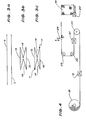
- fig 3a The process of forming the tubular article from which individual containers are formed is shown diagramatically in fig 3.
- fig 3a two superposed layers of fabric 9 are shown each an wide. These are passed through a creasing machine wnich folds each layer of fabric about its mid line and then refolds one half back upon itself as is shown in fig 3b. This material may be rolled up upon itself into a stable roll for further processing. The juxtaposed free edges project by 2.5cm from the adjacent edges of the fabric.
- Fig 3c shows this material after it has been sewn to form the longitudinal seams 11.
- Fig 4 shows diagramatically an arrangement for sewing and cutting the rolled fabric of fig 3b and the formation of the bottom seam 12 to form a container 10.
- the roll of folded fabric 18 is fed past a first sewing machine 19 to form one of the longitudinal seams 11. It is then reversed in direction aroung roller.20 and fed past sewing machine 21 to form the other seam 11.
- After passing around rollers 22 and 23 the fabric is cut into discrete lengths by a cutter 24.
- the cut lengths are sewn along their bottom edge to form seam 12 by sewing machinge 25 and the lifting loops 15 are sewn to the upper edges of the container.
Abstract
A flexible intermediate bulk container is formed from a fabric material and comprises four side walls connected together along the side edges. Two opposed side walls are folded inwardly along their longitudinal axes when the bag is collapsed and lie between two opposed unfolded side walls. The lower ends of the side walls are joined so that when the container is filled the lower ends of the side walls form a rectangular or square base for the container.
A method is described for forming such containers.
Description
- This invention relates to containers for the transport of material and more particularly to flexible bags for the transportation for particulate material in bulk such as powders, pellets, granules, flakes etc. The invention further relates to a method for the fabrication of such containers.
- In recent years there has been an increasing use of bulk containers made of fabric material which is sewn to a suitable shape and provided with lifting loops which may be engaged over the hoop of a crane or the forks of a fork lift truck or similar vehicle. These containers are designed to contain a substantial quantity of material, for example in the range from 250kg to 4 tonnes. A significant part of the cost of such containers, which are known in the art as Flexible Intermediate Bulk Containers (FIBC), is in the fabrication of the bag from the woven fabric. Conventionally such containers are square in cross section and are formed from an elongate run of fabric which is cut into pieces of the designed length which are then sewn up into the finished container. These conventional FIBC containers have been formed with a bottom portion constituted by a single thickness of fabric, which is separate from, and must be sewn to, at least two of the side walls. While this arrangement uses the minimum amount of fabric it does mean that the fabric must be cut before any sewing can take place and that there is a substantial length of sewn seams in each container.
- The present inventor has invented a form of FIBC container in which the bottom of the container is formed by an overlapping of the side walls thereof. This construction considerably reduces fabrication time while offering a number of constructional advantages.
- The present invention consists in a flexible intermediate bulk container formed from a fabric material and comprising four side walls connected together along their side edges, one pair of side walls being folded, when the container is in a collapsed condition, along their longitudinal axis and lying between the other pair of opposed side walls, the four side walls being joined together at their lower end by a seam such that upon the filling of the container the lower ends of the side walls form the base of the container.
- The present invention further consists in a method for the manufacture of a flexible intermediate bulk container having four side walls from a fabric material, comprising positioning between a first pair of lengths of fabric adapted to form opposed side walls of the container a further pair of lengths of fabric adapted to form the other pair of opposed side walls of the container, each one of the further pair of lengths of fabric being folded along its longitudinal axis and having one of its free edges in juxtaposition with one free edge of each of the first pair of lengths of fabric, connecting together such juxtaposed free edges as are not already connected together to form a collapsed tubular member, severing the tubular member into discrete segments of predetermined length and connecting together the adjacent lengths of fabric at one end of each segment.
- As used in this specification the term "fabric" means any woven or non-woven, coated or uncoated, sheet like material.
- FIBC containers are preferably of square cross-section when filled and the containers according to this invention are preferably so formed. It will be apparent, however, that such containers could be rectangular in cross-sectional shape and such rectangular FIBC containers are to be considered to fall within the scope of this invention. It will be appreciated that if an FIBC container according to this invention is to be of a square cross-sectional shape when filled the side walls which are folded along their longitudinal axes (hereinafter called the folded side walls) will abut along their respective fold lines. This in turn means that the seam at the bottom end of the container will join at least four thicknesses of fabric along its full length.
- Where the unfolded side walls are wider than the folded sides the folded sides will not abut against one another along their longitudinal axes when the container is in a collapsed condition. In this case the join between the side wall will have a weakness where the join changes from being of four fabric tnickness to being of two fabric thickness. In this case it is highly desirable to insert a filler to span the space between the two folded side walls. The filler is preferably a piece of fabric folded to be of double thickness. The join can then incorporate the filler and be of four fabric thickness along its whole length.
- The containers according to the present invention may be formed from four discrete lengths of fabric, each of which forms one side wall of the container. In this case it would be necessary to form four longitudinal seams, one joining each pair of juxtaposed free edges of the side walls. It is preferred, however, that the container be formed from only two discrete lengths of fabric each of which forms one of the planar side walls of the container. It is then only necessary to form two longitudinal seams to connect the side walls together. It would also be within the ambit of tnis invention to form the tubular member from which individual containers are cut from a single width of fabric by a single longitudinal seam, the tubular member being then folded to the desired form prior to being severed. It would also be possible to form the containers from a fabric woven in a tubular form provided gusetting and cutting are done as described above.
- The connections between juxtaposed edges of fabric may be formed by sewing, gluing, stapling, heat sealing or any other suitable method. It is, however, preferred that the seams be formed by sewing in a manner known per se. If desired, the longitudinal or transverse seams may be formed after folding over the fabric to be seamed such that the seam is formed through the thickness of the doubled over fabric.
- The containers according to tne present invention are preferably formed with suitable lifting straps in a manner well known in the art. Similarly the containers may be made with a preformed filling opening or spout at its upper end and a preformed discharge opening or spout at its lower end.
- The containers according to tne present invention may be made from any suitable fabric. It is preferred that the fabric be a woven polypropylene which may be coated if desired with an impervious plastics coating. It is particularly preferred that the fabric be reinforced in zones to which the lifting straps are connected. This reinforcement is most preferably formed as described in Australian patent specification 32188/78. In another embodiment of the invention an unreinforced fabric is used. In this embodiment a rope may be formed around the upper end of the container with the rope exposed at each of the four corners of the container to form lifting loops.
- The containers according to the present invention have a number of substantial advantages over known FIBC containers. The base being formed as a continuation of the side walls of the container allows the containers to be folded and stacked much more readily than is possible with known containers having a separate sewn in bottom. The side walls overlap in the region of the bottom of the container when it is filled forming a triangular gusset on either side of the filled container. This allows the container to be gripped by a scissor mechanism on a fork lift truck or the like. Opposed forks on the scissor mechanism can be inserted into the gussets, the scissor mechanism can be then raised up the tower of the fork lift truck when it is in a backwardly inclined position. The raised container can then be discharged by tilting the tower forwardly causing the container to fall forwardly pivoting about the forks of the scissor mechanism. The contents of the container can be discharged through the filling spout of the container when it has been inverted as described above. If this technique is used for moving and emptying the containers the need for a separate discharge spout is removed and the container may be formed without such a discharge spout.
- The method of manufacture of containers according to this invention is best carried out using two discrete lengths of fabric. One length is preferably passed through a creasing machine to fold the fabric in half along its longitudinal axis and then to fold the top half back on itself thus forming integra-ly one planar side wall and one folded side wall. A further length of fabric is simultaneously or sequentially folded in like manner and the two folded lengths brought into juxtaposition with the two folded side walls in side by side abutting relationship between the two opposed planar side walls when square FIBC's are made. The so folded fabric may be rolled up and stored prior to being sewn together. This allows stocks of rolled fabric to be held ready for rapid production of containers of any length.
- Desirably the side edges which are to be sewn project slightly from the fold line along which the integrally formed planar and folded side walls are joined. The folded material may be passed through suitable sewing machines to form the longitudinal seams joining the side walls. The projection of the edges requiring to be sewn facilitates this procedure. If desired, due to the construction of conventional sewing machines, the folded fabric may be moved past a first sewing machine to form a seam on one side of the folded fabric and its direction of movement may then be reversed around a suitable roller or the like and then be moved past a second sewing machine to form a seam on the other side of the folded fabric. Discrete lengths may also be cut prior to sewing.
- If desired the fabric which has been sewn and folded to form a tubular article may be stored or alternatively it may be immediately severed into discrete lengths. When severed one end of the length of tubular material is seamed to form the container. At this stage tops, filling spouts lifting loops or ropes and the like may be added to the container.
- The method according to this invention has distinct advantages over prior art arrangements. The fact that the longitudinal seams are formed prior to cutting of the lengths of fabric substantially speeds their formation. The absence of a separate base member which must be sewn into the container also represents a substantial saving in time.
- Hereinafter given by way of examples is a preferred embodiment of the present invention described with reference to the accompanying drawings in which:-
- Fig 1 is a perspective view from one side of a container according to this invention in an essentially collapsed condition;
- Fig 2 is a perspective view from underneath the container of fig 1 in an expanded or filled condition;
- Figs 3a, b and c show diagramatically stages in the manufacture of a tubular article from which containers according to this invention may be made, and;
- Fig 4 shows diagramatically an arrangement for the manufacture of containers according to this invention.
- The
intermediate bulk container 10 as shown in figs 1 and 2 is formed from two lengths of wovenpolypropylene fabric 9 joined by a pair oflongitudinal seams 11 and abottom seam 12. - The
container 10 has four side walls. Two of theside walls 13 are essentially planar when the container is collapsed and two of theside walls 14 are folded along their longitudinal axes. Each piece offabric 9 is folded to form oneplanar side wall 13 and one foldedside wall 14. The side walls are joined together at their lower ends eg. thebottom seam 12. - The
container 10 is formed witn four liftingstraps 15 each of which is sewn at one end onto aplanar side wall 13 and at the other end onto a foldedside wall 14. - The
container 10 is square in cross-section when filled having nominal sides of lm x lm and a height of 1.6m. When in a collapsed condition the mid line of the foldedside walls 14 will abut or lie closely adjacent one another. - When the
container 10 is filled the lower ends of theside walls base 16 of the container. The lower ends of theside walls 13 form an outer layer of the base 16 which while the corresponding portions of the foldedside walls 14 are folded back on themselves to form triangular gussets 17 (shown in dotted lines in fig 2). - The process of forming the tubular article from which individual containers are formed is shown diagramatically in fig 3. In fig 3a two superposed layers of
fabric 9 are shown each an wide. These are passed through a creasing machine wnich folds each layer of fabric about its mid line and then refolds one half back upon itself as is shown in fig 3b. This material may be rolled up upon itself into a stable roll for further processing. The juxtaposed free edges project by 2.5cm from the adjacent edges of the fabric. Fig 3c shows this material after it has been sewn to form the longitudinal seams 11. - Fig 4 shows diagramatically an arrangement for sewing and cutting the rolled fabric of fig 3b and the formation of the
bottom seam 12 to form acontainer 10. The roll of foldedfabric 18 is fed past afirst sewing machine 19 to form one of the longitudinal seams 11. It is then reversed in direction aroung roller.20 and fedpast sewing machine 21 to form theother seam 11. After passing aroundrollers cutter 24. The cut lengths are sewn along their bottom edge to formseam 12 bysewing machinge 25 and the liftingloops 15 are sewn to the upper edges of the container.
Claims (14)
1. A flexible intermediate bulk container formed from a fabric material and comprising four side walls connected together along their side edges, one pair of side walls being folded, when the container is in a collapsed condition, along their longitudinal axes and lying between the other pair of opposed side walls, the four side walls being joined together at their lower end by a seam such that upon the filling of the container the lower ends of the side walls form the base of the container.
2. A flexible intermediate bulk container as claimed in Claim 1 in which the side walls which are folded abut against one another along their longitudinal axes at least in the region of the join between the four side walls.
3. A flexible intermediate bulk container as claimed in Claim 1 in which the side walls which are folded do not abut along their longitudinal axes in the region of the join between the four side walls and a filler is positioned in the space between the two folded side walls and between the two unfolded side walls in the region of the said join and which forms part of that join.
4. A flexible intermediate bulk container as claimed in Claim 1 in which the filler comprises two thicknesses of the fabric material such that the join is of four thicknesses along its whole length.
5. A flexible intermediate bulk container as claimed in Claim 1 in which the container is formed from two pieces of the fabric material joined longitudinally along two diagonally opposite connections between the four side walls by a sewn seam.
6. A flexible intermediate bulk container as claimed in claim 5 in which the seams between the two pieces of the fabric material extend, when the container is in a collapsed condition, laterally slightly beyond the adjacent line of connections between two side walls of the container.
7. A flexible intermediate bulk container as claimed in Claim 1 in which the fabric material is made of woven polypropylene.
8. A method for the manufacture of a flexible intermediate bulk container having four side walls from a fabric material, comprising positioning between a first pair of lengths of fabric adapted to form opposed side walls of the container a further pair of lengths of fabric adapted to form the other pair of opposed side walls of the container, each one of the further pair of lengths of fabric being folded along its longitudinal axis and having one of its free edges in juxtaposition with one free edge of each of the first pair of lengths of fabric, connecting together such juxtaposed free edges as are not already connected together to form a collapsed tubular member, severing the tubular member into discrete segments of predetermined length and connecting together the adjacent lengths of fabric at one end of each segment.
9. A method as claimed in Claim S in which the container is formed from two pieces of the fabric material each piece constituting one folded side wall and one unfolded side wall.
10. A method as claimed in Claim 9 in which the free side edges of each piece of fabric material projects slightly beyond the adjacent connection between the folded and unfolded side wall constituted by that piece of fabric material.
ll. A method as claimed in Claim 9 or Claim 10 in which the folded fabric is moved past a first sewing machine to join the two pieces of fabric material on one side, the direction of movement is reversed around a roller or like support and the folded fabric is mcved past a second sewing machine to join the two pieces of fabric material on the other side.
12. A method as claimed in any one of Claims 8 to 11 in which the free edges of the fabric material are joined together prior to the tubular member being cut into discrete lengths.
13. A method as claimed in any one of Claims 8 to 12 in which the fabric material is joined by sewing.
14. A flexible intermediate bulk container made by a method according to any one of Claims 8 to 13.
Applications Claiming Priority (2)
| Application Number | Priority Date | Filing Date | Title |
|---|---|---|---|
| AU8734/83 | 1983-04-05 | ||
| AUPF873483 | 1983-04-05 |
Publications (1)
| Publication Number | Publication Date |
|---|---|
| EP0121266A1 true EP0121266A1 (en) | 1984-10-10 |
Family
ID=3770075
Family Applications (1)
| Application Number | Title | Priority Date | Filing Date |
|---|---|---|---|
| EP84103738A Withdrawn EP0121266A1 (en) | 1983-04-05 | 1984-04-04 | Flexible intermediate bulk container |
Country Status (3)
| Country | Link |
|---|---|
| EP (1) | EP0121266A1 (en) |
| AU (1) | AU2676184A (en) |
| ZA (1) | ZA842599B (en) |
Cited By (4)
| Publication number | Priority date | Publication date | Assignee | Title |
|---|---|---|---|---|
| EP0382951A1 (en) * | 1989-02-06 | 1990-08-22 | Condepols, S.A. | Method for manufacturing a flexible material container for transporting and storing products in bulk |
| GB2229992A (en) * | 1986-08-21 | 1990-10-10 | Hosokawa Yoko Kk | Beverage container |
| US5213418A (en) * | 1991-06-13 | 1993-05-25 | Kristen Dancy | Reusable bag |
| US5461040A (en) * | 1989-05-13 | 1995-10-24 | Ciba-Geigy Corporation | Substituted aminoalkylphosphinic acids |
Citations (3)
| Publication number | Priority date | Publication date | Assignee | Title |
|---|---|---|---|---|
| DE2046129A1 (en) * | 1970-09-18 | 1972-04-13 | Nord-West-Papierwerk Karl Götze, 5253 Lindlar | Deep fold sack |
| US3998970A (en) * | 1975-04-28 | 1976-12-21 | Stauffer Chemical Company | N,N-dimethyl-N'-phenylthiocarbamyl formamidine and its use as an anti-inflammatory agent |
| DE2607065A1 (en) * | 1976-02-21 | 1977-08-25 | Spohn Kg | Large high-strength bag woven from plastic strips - esp. as continuous tube for cheap throwaway use |
-
1983
- 1983-04-05 AU AU26761/84A patent/AU2676184A/en not_active Abandoned
-
1984
- 1984-04-04 ZA ZA842599A patent/ZA842599B/en unknown
- 1984-04-04 EP EP84103738A patent/EP0121266A1/en not_active Withdrawn
Patent Citations (3)
| Publication number | Priority date | Publication date | Assignee | Title |
|---|---|---|---|---|
| DE2046129A1 (en) * | 1970-09-18 | 1972-04-13 | Nord-West-Papierwerk Karl Götze, 5253 Lindlar | Deep fold sack |
| US3998970A (en) * | 1975-04-28 | 1976-12-21 | Stauffer Chemical Company | N,N-dimethyl-N'-phenylthiocarbamyl formamidine and its use as an anti-inflammatory agent |
| DE2607065A1 (en) * | 1976-02-21 | 1977-08-25 | Spohn Kg | Large high-strength bag woven from plastic strips - esp. as continuous tube for cheap throwaway use |
Cited By (5)
| Publication number | Priority date | Publication date | Assignee | Title |
|---|---|---|---|---|
| GB2229992A (en) * | 1986-08-21 | 1990-10-10 | Hosokawa Yoko Kk | Beverage container |
| GB2229992B (en) * | 1986-08-21 | 1991-04-24 | Hosokawa Yoko Kk | Beverage container |
| EP0382951A1 (en) * | 1989-02-06 | 1990-08-22 | Condepols, S.A. | Method for manufacturing a flexible material container for transporting and storing products in bulk |
| US5461040A (en) * | 1989-05-13 | 1995-10-24 | Ciba-Geigy Corporation | Substituted aminoalkylphosphinic acids |
| US5213418A (en) * | 1991-06-13 | 1993-05-25 | Kristen Dancy | Reusable bag |
Also Published As
| Publication number | Publication date |
|---|---|
| AU2676184A (en) | 1984-10-11 |
| ZA842599B (en) | 1984-11-28 |
Similar Documents
| Publication | Publication Date | Title |
|---|---|---|
| RU2282571C2 (en) | Product container and manufacturing method | |
| US5104236A (en) | Scrapless collapsible bag with circumferentially spaced reinforced strips | |
| US4759473A (en) | Collapsible receptacle with integral sling | |
| US4457456A (en) | Collapsible receptacle with static electric charge elimination | |
| US4479243A (en) | Collapsible receptacle with prefabricated lift loops and method of making | |
| EP0302191B1 (en) | Collapsible bag and method of making the same | |
| US5127893A (en) | Method of making scrapless collapsible bag with circumferentially spaced reinforced strips | |
| KR950000585B1 (en) | Cargo bag and method of forming same | |
| CA2299918C (en) | Method for producing packaging means made of plastic foil or similar heat-sealable material | |
| US4781475A (en) | Reinforced bulk bag | |
| US7476028B2 (en) | Bulk bag for meat and meat products | |
| US4224970A (en) | Collapsible receptacle for flowable materials | |
| US5328267A (en) | Bulk containers | |
| US6371646B1 (en) | Bulk bag with multiple ply walls and a method of forming it from tubular blanks | |
| EP0083505A1 (en) | Collapsible receptacle with prefabricated lift loops and method of making same | |
| AU632100B2 (en) | A flexible container with improved bottom and top | |
| US5865540A (en) | One piece flexible intermediate bulk container and process for manufacturing same | |
| US5758973A (en) | Bulk bag with reinforced lift straps | |
| US5842789A (en) | One piece flexible intermediate bulk container and process for manufacturing same | |
| US4798572A (en) | Collapsible bag and method | |
| US4610029A (en) | Bag to be carried in the hand and procedure for manufacturing the bag | |
| CA1158574A (en) | Collapsible receptacle with integral sling | |
| EP0121266A1 (en) | Flexible intermediate bulk container | |
| GB2092990A (en) | Bag for bulk material | |
| EP0229020A2 (en) | Container for transport and storage of bulk material |
Legal Events
| Date | Code | Title | Description |
|---|---|---|---|
| PUAI | Public reference made under article 153(3) epc to a published international application that has entered the european phase |
Free format text: ORIGINAL CODE: 0009012 |
|
| AK | Designated contracting states |
Designated state(s): AT BE CH DE FR GB IT LI LU NL SE |
|
| STAA | Information on the status of an ep patent application or granted ep patent |
Free format text: STATUS: THE APPLICATION IS DEEMED TO BE WITHDRAWN |
|
| 18D | Application deemed to be withdrawn |
Effective date: 19850611 |