EP0120791A1 - Klemmschelle, vorzugsweise für Auspuffleitungen bei Kraftfahrzeugmotoren - Google Patents
Klemmschelle, vorzugsweise für Auspuffleitungen bei Kraftfahrzeugmotoren Download PDFInfo
- Publication number
- EP0120791A1 EP0120791A1 EP84400608A EP84400608A EP0120791A1 EP 0120791 A1 EP0120791 A1 EP 0120791A1 EP 84400608 A EP84400608 A EP 84400608A EP 84400608 A EP84400608 A EP 84400608A EP 0120791 A1 EP0120791 A1 EP 0120791A1
- Authority
- EP
- European Patent Office
- Prior art keywords
- collar
- zone
- deformable
- periphery
- tube
- Prior art date
- Legal status (The legal status is an assumption and is not a legal conclusion. Google has not performed a legal analysis and makes no representation as to the accuracy of the status listed.)
- Withdrawn
Links
Images

Classifications
-
- F—MECHANICAL ENGINEERING; LIGHTING; HEATING; WEAPONS; BLASTING
- F01—MACHINES OR ENGINES IN GENERAL; ENGINE PLANTS IN GENERAL; STEAM ENGINES
- F01N—GAS-FLOW SILENCERS OR EXHAUST APPARATUS FOR MACHINES OR ENGINES IN GENERAL; GAS-FLOW SILENCERS OR EXHAUST APPARATUS FOR INTERNAL COMBUSTION ENGINES
- F01N13/00—Exhaust or silencing apparatus characterised by constructional features ; Exhaust or silencing apparatus, or parts thereof, having pertinent characteristics not provided for in, or of interest apart from, groups F01N1/00 - F01N5/00, F01N9/00, F01N11/00
- F01N13/18—Construction facilitating manufacture, assembly, or disassembly
- F01N13/1805—Fixing exhaust manifolds, exhaust pipes or pipe sections to each other, to engine or to vehicle body
-
- F—MECHANICAL ENGINEERING; LIGHTING; HEATING; WEAPONS; BLASTING
- F16—ENGINEERING ELEMENTS AND UNITS; GENERAL MEASURES FOR PRODUCING AND MAINTAINING EFFECTIVE FUNCTIONING OF MACHINES OR INSTALLATIONS; THERMAL INSULATION IN GENERAL
- F16L—PIPES; JOINTS OR FITTINGS FOR PIPES; SUPPORTS FOR PIPES, CABLES OR PROTECTIVE TUBING; MEANS FOR THERMAL INSULATION IN GENERAL
- F16L33/00—Arrangements for connecting hoses to rigid members; Rigid hose connectors, i.e. single members engaging both hoses
- F16L33/02—Hose-clips
- F16L33/025—Hose-clips tightened by deforming radially extending loops or folds
Definitions
- the present invention therefore relates to a clamp, in particular for fixing two metal tubes fitted one inside the other, such a collar comprising an area liable to undergo permanent deformation at the time of tightening, that is ie when it is necessary to reduce the length of its internal periphery.
- the deformable zone of the collar consists of a flat surface extending radially in the plane of the collar.
- the collar is constituted by a flat ring, preferably cut from a sheet blank, the deformable zone having radial dimensions at least equal, and preferably substantially greater than those of the current part of the 'ring.
- the invention can also be applied to various known types of collars and in particular to those described in patent FR-A 2491163, that is to say collars in two parts, intended in particular to constitute spare parts.
- Such collars comprise a stirrup in the form of a rider with divergent branches, the ends of which are provided with stops cooperating with a flange.
- the middle part of the latter has a curved shape which corresponds to that of the tube to be clamped.
- the invention will advantageously be implemented by making the jumper in the form of a partially annular flat sheet metal element, the deformable zone of the collar being provided on this jumper and having radial dimensions at least equal and preferably greater than those of the current part of the annular portion.
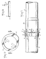
- the collar is constituted by a simple flat ring 1 cut from a sheet blank.
- the internal periphery 2 of the collar has a diameter slightly greater than that of the tube 3 on which it must be mounted.
- the ring 1 has a substantially constant radial dimension, but a zone 4 preferably extends radially beyond the main part towards the outside and is suitably connected to the latter.
- Zone 4 is capable of being permanently deformed under conditions which will be specified later, but it should be noted here that it is obtained directly at the time of cutting of the sheet blank and that it in principle has the same thickness as the rest of the necklace.
- the cutting of the ring will preferably leave tabs 5 attached to the internal periphery. These tabs are shown in dotted line in Figure 1 because they are intended, immediately after cutting the sheet blank to be folded perpendicular to the plane of the collar and to receive another fold at their free end to form a hook 6 directed towards the 'axis of the collar ( Figure 2).
- the manufacture of the collar is particularly simple and requires, as we have seen, only a cutting operation possibly followed by folding operations.
- the assembly and tightening of a collar is also very easy and quick.
- the collar is first of all threaded onto the tube 3 to be tightened until its hooks 6 abut on the end of the tube. Its position is then completely satisfactory since the length of the legs 5 will correspond to approximately half the length of the slots 8 formed at the end of the tube 3.
- a second tube 9 is then fitted into the tube 3 until come into abutment in the terminal bulge (3a) generally provided thereon.
- the slots 8 are then closed by the tube 9.
- the clamping of the collar is obtained by creating, by permanent deformation, radial undulations 10 in the deformable zone 4 which has the effect of reducing the internal periphery of the ring and of strongly pressing the tube 3 on the tube 9.
- This operation is preferably carried out by means of a simple pliers, for example with a toggle joint, the jaws 11 of which have the shape visible in FIG. 5.
- the undulations 11a of the jaws will show corresponding undulations 10 in the deformable zone 4, visible in figure 2.
- the jumper itself is similar to what has been described above cut from a sheet blank and has the deformable zone 4 of the collar. It can also be provided with one or more tabs similar to those described above.
Landscapes
- Engineering & Computer Science (AREA)
- General Engineering & Computer Science (AREA)
- Mechanical Engineering (AREA)
- Chemical & Material Sciences (AREA)
- Combustion & Propulsion (AREA)
- Clamps And Clips (AREA)
- Cooling, Air Intake And Gas Exhaust, And Fuel Tank Arrangements In Propulsion Units (AREA)
- Exhaust Silencers (AREA)
- Joints With Sleeves (AREA)
- Joints That Cut Off Fluids, And Hose Joints (AREA)
- Mutual Connection Of Rods And Tubes (AREA)
Applications Claiming Priority (2)
| Application Number | Priority Date | Filing Date | Title |
|---|---|---|---|
| FR8305148 | 1983-03-29 | ||
| FR8305148A FR2543626B1 (fr) | 1983-03-29 | 1983-03-29 | Collier de serrage, en particulier pour tuyaux d'echappement de moteurs pour vehicules automobiles |
Publications (1)
| Publication Number | Publication Date |
|---|---|
| EP0120791A1 true EP0120791A1 (de) | 1984-10-03 |
Family
ID=9287343
Family Applications (1)
| Application Number | Title | Priority Date | Filing Date |
|---|---|---|---|
| EP84400608A Withdrawn EP0120791A1 (de) | 1983-03-29 | 1984-03-27 | Klemmschelle, vorzugsweise für Auspuffleitungen bei Kraftfahrzeugmotoren |
Country Status (4)
| Country | Link |
|---|---|
| EP (1) | EP0120791A1 (de) |
| JP (1) | JPS59190419A (de) |
| ES (1) | ES286679Y (de) |
| FR (1) | FR2543626B1 (de) |
Cited By (1)
| Publication number | Priority date | Publication date | Assignee | Title |
|---|---|---|---|---|
| FR2662487A1 (fr) * | 1990-05-23 | 1991-11-29 | Caillau Ets | Collier de serrage. |
Families Citing this family (1)
| Publication number | Priority date | Publication date | Assignee | Title |
|---|---|---|---|---|
| JPH0797592B2 (ja) * | 1985-07-02 | 1995-10-18 | ソニー株式会社 | 電界効果型トランジスタ |
Citations (3)
| Publication number | Priority date | Publication date | Assignee | Title |
|---|---|---|---|---|
| DE1775916A1 (de) * | 1966-02-18 | 1971-11-18 | Hans Oetiker | Klemmbride |
| DE2627011A1 (de) * | 1976-06-16 | 1977-12-29 | Volkswagenwerk Ag | Leicht loesbare verbindung zweier korrosionsgefaehrdeter rohre |
| FR2435624A1 (fr) * | 1978-09-08 | 1980-04-04 | Donaldson Co Inc | Dispositif de blocage a boulon en u |
-
1983
- 1983-03-29 FR FR8305148A patent/FR2543626B1/fr not_active Expired
-
1984
- 1984-03-27 EP EP84400608A patent/EP0120791A1/de not_active Withdrawn
- 1984-03-28 JP JP6052584A patent/JPS59190419A/ja active Pending
- 1984-03-28 ES ES1984286679U patent/ES286679Y/es not_active Expired
Patent Citations (3)
| Publication number | Priority date | Publication date | Assignee | Title |
|---|---|---|---|---|
| DE1775916A1 (de) * | 1966-02-18 | 1971-11-18 | Hans Oetiker | Klemmbride |
| DE2627011A1 (de) * | 1976-06-16 | 1977-12-29 | Volkswagenwerk Ag | Leicht loesbare verbindung zweier korrosionsgefaehrdeter rohre |
| FR2435624A1 (fr) * | 1978-09-08 | 1980-04-04 | Donaldson Co Inc | Dispositif de blocage a boulon en u |
Cited By (1)
| Publication number | Priority date | Publication date | Assignee | Title |
|---|---|---|---|---|
| FR2662487A1 (fr) * | 1990-05-23 | 1991-11-29 | Caillau Ets | Collier de serrage. |
Also Published As
| Publication number | Publication date |
|---|---|
| ES286679U (es) | 1985-12-16 |
| FR2543626A1 (fr) | 1984-10-05 |
| FR2543626B1 (fr) | 1985-08-09 |
| JPS59190419A (ja) | 1984-10-29 |
| ES286679Y (es) | 1986-07-16 |
Similar Documents
| Publication | Publication Date | Title |
|---|---|---|
| EP2156088B1 (de) | Spannvorrichtung | |
| EP0511891B1 (de) | Verbindungselement zur Schnellkupplung eines Rohres | |
| WO2003048624A1 (fr) | Systeme de serrage pour le raccordement etanche de deux tubes ayant des surfaces d'appui. | |
| FR2664347A1 (fr) | Anneau de serrage a extremites jointes, notamment pour la fixation de soufflets, et procede de fabrication de cet anneau. | |
| WO1999050583A1 (fr) | Raccord encliquetable pour tuyaux | |
| BE898358A (fr) | Structure de serrage sans oreille. | |
| EP0219418A1 (de) | Vorrichtung zum Verbinden eines elastisch verformbaren Rohres mit einem starren Rohr | |
| EP0296919B2 (de) | Schlauchklemme | |
| EP0280598B1 (de) | Spannschelle mit Elastizitätsreserve | |
| EP0403379A1 (de) | Verbindungsschelle für Auspuffleitungen | |
| EP0617217B1 (de) | Rohr, insbesondere für ein Kraftfahrzeug | |
| FR2842276A1 (fr) | Collier de serrage | |
| EP0120791A1 (de) | Klemmschelle, vorzugsweise für Auspuffleitungen bei Kraftfahrzeugmotoren | |
| EP0737114A1 (de) | Einschnürungsverfahren | |
| EP0890778B1 (de) | Geschlitzte Hülse aus Kautschuk oder ähnlichem Material zum Verbinden einer Befestigungslasche an ein starres Rohr | |
| FR2705410A1 (fr) | Collier de serrage. | |
| EP4040027A1 (de) | Schlauchklemme mit einem halteelement und einem haken | |
| FR2921422A1 (fr) | Piece annulaire de turbomachine portant des ecrous a jupe de sertissage | |
| EP1231422A1 (de) | Verfahren zur Herstellung einer unverlierbaren Schraube, Fixierungstellringe für Rohrleitungen und Gebrauch von dem Prozess, die Stellringe herzustellen | |
| FR2602572A1 (fr) | Dispositif de raccordement d'un tuyau souple autour d'un embout tubulaire rigide | |
| EP0907857A1 (de) | Schlauchschelle. | |
| EP0710794A1 (de) | Vorrichtung zum Verbinden eines Rohres an einem Rohreinsatz | |
| FR2588357A1 (fr) | Conduit de fumee metallique a simple paroi | |
| FR2787171A1 (fr) | Dispositif de raccordement demontable pour le raccordement d'un tube rigide ou semi-rigide et d'une interface rigide | |
| EP3795877B1 (de) | Schlauchklemme |
Legal Events
| Date | Code | Title | Description |
|---|---|---|---|
| PUAI | Public reference made under article 153(3) epc to a published international application that has entered the european phase |
Free format text: ORIGINAL CODE: 0009012 |
|
| AK | Designated contracting states |
Designated state(s): BE DE GB IT NL SE |
|
| 17P | Request for examination filed |
Effective date: 19850313 |
|
| 17Q | First examination report despatched |
Effective date: 19861021 |
|
| STAA | Information on the status of an ep patent application or granted ep patent |
Free format text: STATUS: THE APPLICATION HAS BEEN WITHDRAWN |
|
| 18W | Application withdrawn |
Withdrawal date: 19861208 |
|
| RIN1 | Information on inventor provided before grant (corrected) |
Inventor name: CALMETTES, LIONEL |