EP0120782A1 - Method and apparatus for tapping a pipeline in a controlled atmosphere, particularly a nuclear plant pipeline - Google Patents
Method and apparatus for tapping a pipeline in a controlled atmosphere, particularly a nuclear plant pipeline Download PDFInfo
- Publication number
- EP0120782A1 EP0120782A1 EP19840400585 EP84400585A EP0120782A1 EP 0120782 A1 EP0120782 A1 EP 0120782A1 EP 19840400585 EP19840400585 EP 19840400585 EP 84400585 A EP84400585 A EP 84400585A EP 0120782 A1 EP0120782 A1 EP 0120782A1
- Authority
- EP
- European Patent Office
- Prior art keywords
- pipe
- groove
- wall
- cutting
- welding
- Prior art date
- Legal status (The legal status is an assumption and is not a legal conclusion. Google has not performed a legal analysis and makes no representation as to the accuracy of the status listed.)
- Granted
Links
Images


Classifications
-
- F—MECHANICAL ENGINEERING; LIGHTING; HEATING; WEAPONS; BLASTING
- F16—ENGINEERING ELEMENTS AND UNITS; GENERAL MEASURES FOR PRODUCING AND MAINTAINING EFFECTIVE FUNCTIONING OF MACHINES OR INSTALLATIONS; THERMAL INSULATION IN GENERAL
- F16L—PIPES; JOINTS OR FITTINGS FOR PIPES; SUPPORTS FOR PIPES, CABLES OR PROTECTIVE TUBING; MEANS FOR THERMAL INSULATION IN GENERAL
- F16L41/00—Branching pipes; Joining pipes to walls
- F16L41/04—Tapping pipe walls, i.e. making connections through the walls of pipes while they are carrying fluids; Fittings therefor
-
- Y—GENERAL TAGGING OF NEW TECHNOLOGICAL DEVELOPMENTS; GENERAL TAGGING OF CROSS-SECTIONAL TECHNOLOGIES SPANNING OVER SEVERAL SECTIONS OF THE IPC; TECHNICAL SUBJECTS COVERED BY FORMER USPC CROSS-REFERENCE ART COLLECTIONS [XRACs] AND DIGESTS
- Y10—TECHNICAL SUBJECTS COVERED BY FORMER USPC
- Y10T—TECHNICAL SUBJECTS COVERED BY FORMER US CLASSIFICATION
- Y10T137/00—Fluid handling
- Y10T137/0318—Processes
- Y10T137/0402—Cleaning, repairing, or assembling
- Y10T137/0441—Repairing, securing, replacing, or servicing pipe joint, valve, or tank
- Y10T137/0458—Tapping pipe, keg, or tank
- Y10T137/0463—Particular aperture forming means
- Y10T137/0469—Cutter or cutting tool
-
- Y—GENERAL TAGGING OF NEW TECHNOLOGICAL DEVELOPMENTS; GENERAL TAGGING OF CROSS-SECTIONAL TECHNOLOGIES SPANNING OVER SEVERAL SECTIONS OF THE IPC; TECHNICAL SUBJECTS COVERED BY FORMER USPC CROSS-REFERENCE ART COLLECTIONS [XRACs] AND DIGESTS
- Y10—TECHNICAL SUBJECTS COVERED BY FORMER USPC
- Y10T—TECHNICAL SUBJECTS COVERED BY FORMER US CLASSIFICATION
- Y10T137/00—Fluid handling
- Y10T137/598—With repair, tapping, assembly, or disassembly means
- Y10T137/612—Tapping a pipe, keg, or apertured tank under pressure
- Y10T137/6123—With aperture forming means
Definitions
- the present invention relates to a method for creating a nozzle in a controlled atmosphere on a pipe, in particular a pipe for a nuclear power plant, as well as a device for its implementation.
- switching we mean a lateral grip made in the form of a tubing (of circular or rectangular section) blind of short length and diameter much smaller than that of the pipe, oriented perpendicularly to the axis of this pipe .
- This lateral socket is used during interventions on the pipe: the nozzle is opened by cutting the tubing, which allows all kinds of devices to be passed inside the pipe, both for repair and maintenance (and in particular flexible shut-off balloons ensuring, after inflation inside the pipe, the circuit is sealed against the outside) only for checking the integrity of the pipe (gamma control in particular).
- One of the objects of the invention is to allow the creation of such a tapping without requiring a long-term shutdown of the installation, thanks in particular to the possibility of maintaining the circuits under atmosphere during, before and after the intervention. controlled by neutral gas (for example under an argon atmosphere), and to intervene while the circuits are still tempered rature, that is to say values up to 180 ° C.
- neutral gas for example under an argon atmosphere
- the welding of the blind tapping pipe is done by welding a tubular sleeve, followed by a sealing of this sleeve by welding a cover.
- a device for recovering machining debris is introduced and deployed inside the pipe, which will be closed and removed before the tubular sleeve is closed.
- the recovery device can also be provided for defining and sealingly isolating a work area located in the vicinity of the opening, and partly included inside the pipe.
- the sealed insulation member can advantageously be removed during the entire duration of the operations carried out with the recovery device in place.
- the invention also provides a device comprising: a cutting tool capable of digging a groove at the location of the tapping to be made; means for adjusting the depth of the cutting tool; feeler means able to follow the surface of the pipe in the vicinity of the cutting tool and cooperating with the above means so as to adjust the cutting depth to a value slightly less than the thickness of the wall and allow the bottom to remain from the groove a metal veil of constant thickness at any point of the groove, as well as means for moving the cutting tool along a pre-established path corresponding to the cutting to be made.
- the invention also provides a ripper device comprising: a support bearing entirely on the area of the pipe wall located outside the area defined by the groove; a cutting template, placed on the support, carrying a guide groove placed above and to the right of the groove, as well as a knockout tool guided by the groove of the template.
- a ripper device comprising: a support bearing entirely on the area of the pipe wall located outside the area defined by the groove; a cutting template, placed on the support, carrying a guide groove placed above and to the right of the groove, as well as a knockout tool guided by the groove of the template.
- the grooving device and the knockout device are guided or supported by a tool centering support previously welded, in the center of the area where the opening must be made, on the wall of the pipe. This support of centering also makes it possible, when the wall is routed, to grasp the cut fraction of the wall and to prevent it from falling inside the pipe.
- the tool centering support 100 composed for example of a rod 110 screwed in the center of a plate 120 to be welded to the wall of the pipe.
- the operator ultrasonically measures the thickness of the pipe in the area to be cut.
- FIG. 2 It can then put in place (FIG. 2) the grooving machine 300, supported by the rod 110. This machine is then adjusted to machine the groove 13 in depth so as to leave a metal veil 14 (visible in FIG. 3b). a few tenths of millimeter thick.
- FIG. 3a (with the enlarged detail in FIG. 3b) schematically shows the structure of this machine: it comprises a cutting tool 310, for example a cylindrical cutter making it possible to dig the groove.
- Means 330 are provided for adjusting the depth of this cutter, the position of the surface of the pipe being determined for example by a feeler 320. It is thus possible to follow the surface of the pipe in the vicinity of the cutter 310 over all the cutting path, and although this follows a left profile (corresponding, in the case of a stitching by circular tubing, at the intersection of two cylinders).
- Means 340 are also provided for moving the cutting tool along a predetermined path corresponding to the cutting to be made, for example a circular path, seen in plan.
- This insulation member is for example made up of a glove box allowing the operator to work freely while providing insulation.
- This glove box can for example be subject to an inflatable base 400 ( Figure 4) matching the external shape of the pipe and fixed to it by straps 410.
- the base supports a flange 420 allowing the box to be fixed in gloves.
- the base is an inflatable seal by blowing pressurized gas through the valve 430.
- the actual glove 440 ( Figure 5) is then sealingly attached to the flange 420. This is for exam- p the parallelepipedic or cylindrical enclosure 450 reinforced elastomer provided with an airlock 460 for introducing tools, portholes 470 and gloves 480 for the operator.
- the recovery device is for example that described in French application No. 83- in the name of the Applicant.
- the device described in this application ensures, once deployed inside the pipe below the orifice, not only the recovery of chips and other debris caused by the machining operations on this orifice, but also the sealing between the inside of the pipe and the outside atmosphere. It is thus possible to carry out in the open air all operations, including welds with reverse flow, on the open opening in the pipe.
- this device supported and guided by the support 100, includes a cutting template 610 placed on a support 620 bearing entirely on the area of the wall of the pipe located outside the area defined by the groove.
- the template has a guide groove 630, in line with the groove, making it possible to guide a knockout tool 640.
- the groove 630 is made on a fraction of a circle , and the operator rotates the template 610 as the circumference portions are knocked out.
- the routing is done without producing chips (therefore without introduction of bodies foreigners in the pipe) and without deformation of the metal wall of the pipe.
- the central fraction of the wall, cut remains retained by the rod 110 of the tool holder; in fact, this rod remains connected, for example by a nut 650, to the support 620 of the ripping device: this avoids that, at the end of ripping, the cut fraction does not fall to the bottom of the pipe.
- Figure 8 shows this device deployed inside the pipe: an inflatable seal 510, pressed inside the pipe, around the orifice, by a telescopic foot 520, ensures the tight fixing of a flexible veil 530 recovering debris and insulating the interior of the pipe, which can be maintained under a controlled atmosphere of neutral gas.
- a chamfer 15 is then made (FIG. 9) on the orifice to allow the welding of a tubular sleeve 16 (FIG. 10) by means of a torch 700, in a conventional manner.
- the weld is observed, in particular its reverse side by means of a mirror device 800 (FIG. 11), then checked by radiography.
- the glove box is then replaced, the recovery device 500 removed from the pipe ( Figure 12) and a sealing cap 18 welded to the end of the sleeve.
- This welding is preferably carried out without filler metal, by an electrode device refractory (TIG welding).
- the glove box is then removed and the insulation reinstalled.
- FIG. 13 shows a variant of a grooving machine, still in the case of a circular drilling, in which the milling tool 310 is supported by a rod 331, preferably a square rod preventing any axial rotation.
- the tool is brought into flush with the surface of the pipe by a vernier 332. It is then a jack 330, for example a double body jack ensuring a low pressure force but an important precision, which will control the controlled descent of the tool at desired depth.
- An encoder 350 transmits the depth information to the jack 330.
- a motor 340 associated with a reduction gear 341 driving the tool support 342, drives the latter along the pre-established path.
- the whole machine can for example be supported by a frame 360 fixed to the pipe 10 by means of straps 370 surrounding the latter.
- Figures 14 and 15 show another possibility of a routing tool for a circular opening: the tool then consists of a serrated perforator 660 movable around the rod 110 welded in the center of the area to be cut, for example by means a thrust ball bearing 670. It then suffices for the operator to place the punch above the groove 13 and perform minor percussion s thereon to break down, without the production of chips, the metal veil . Percussion can also be replaced by a mechanical vibrating system.
- Figure 18 shows a router for rectangular cutting device, similar to the device of Figures 6a and 6b provided for a circular groove: the device also includes a template 610 'placed on a base 620'.
- the groove 630 ′ for guiding the tool 640 then has a straight profile.
- the rod 110 of the tool support ensures, as before, the centering of the different parts.
Landscapes
- Engineering & Computer Science (AREA)
- General Engineering & Computer Science (AREA)
- Mechanical Engineering (AREA)
- Butt Welding And Welding Of Specific Article (AREA)
- Milling Processes (AREA)
- Branch Pipes, Bends, And The Like (AREA)
- Arc Welding In General (AREA)
Abstract
Ce procédé comporte les étapes de: creusement dans la paroi de la conduite, à l'emplacement du piquage à réaliser, d'une gorge continue (13) de profondeur légèrement inférieure à l'épaisseur de la paroi, de manière à laisser subsister au fond de la gorge un voile (14) de métal entre l'intérieur de la tuyauterie et l'atmosphère extérieure ; mise en place sur la tuyauterie d'un organe d'isolation étanche recouvrant une zone d'étendue au moins égale à celle de la zone délimitée par la gorge; défonçage du voile de métal de manière à pratiquer une ouverture dans la conduite ; retrait de la fraction découpée de la paroi ; soudage d'une conduite borgne de piquage ; retrait de l'organe d'isolation étanche.This method comprises the steps of: digging into the wall of the pipe, at the location of the tapping to be produced, a continuous groove (13) of depth slightly less than the thickness of the wall, so as to allow the bottom of the groove a veil (14) of metal between the interior of the piping and the external atmosphere; placement of a sealed insulation member on the piping covering an area of extent at least equal to that of the area delimited by the groove; breaking the metal veil so as to make an opening in the pipe; removal of the cut fraction from the wall; welding of a blind tapping pipe; removal of the sealed insulation member.
L'invention concerne également un dispositif pour creuser cette gorge et un dispositif (600) pour le défonçage final du voile de métal.
Description
La présente invention concerne un procédé de création d'un piquage en atmosphère contrôlée sur une tuyauterie, notamment une tuyauterie de centrale nucléaire, ainsi qu'un dispositif pour sa mise en oeuvre.The present invention relates to a method for creating a nozzle in a controlled atmosphere on a pipe, in particular a pipe for a nuclear power plant, as well as a device for its implementation.
Par "piquage", on entendra une prise latérale réalisée sous forme d'une tubulure (de section circulaire ou rectangulaire) borgne de courte longueur et de diamètre très inférieur à celui de la conduite, orientée perpendiculairement par rapport à l'axe de cette conduite. Cette prise latérale est utilisée lors des interventions sur la conduite : on ouvre le piquage par découpe de la tubulure, ce qui permet de passer à l'intérieur de la conduite toutes sortes d'appareils, tant pour la réparation et l'entretien (et notamment des ballons obturateurs souples assurant, après gonflage à l'intérieur de la conduite, l'étanchéité du circuit vis-à-vis de l'extérieur) que pour le contrôle de l'intégrité de la conduite (contrôle gammagraphique en particulier).By "stitching", we mean a lateral grip made in the form of a tubing (of circular or rectangular section) blind of short length and diameter much smaller than that of the pipe, oriented perpendicularly to the axis of this pipe . This lateral socket is used during interventions on the pipe: the nozzle is opened by cutting the tubing, which allows all kinds of devices to be passed inside the pipe, both for repair and maintenance (and in particular flexible shut-off balloons ensuring, after inflation inside the pipe, the circuit is sealed against the outside) only for checking the integrity of the pipe (gamma control in particular).
Jusqu'à présent, ces piquages étaient prévus au moment de la conception de l'installation en des emplacements appropriés, et réalisés en même temps que celle-ci. La création d'un piquage additionnel sur une conduite préexistante supposait des travaux de grande ampleur et de longue durée pour pouvoir isoler, vidanger, refroidir et démonter la partie de l'installation à modifier.Until now, these tappings were planned at the time of the design of the installation in appropriate locations, and carried out at the same time as this. The creation of an additional tapping on a preexisting pipe required large-scale and long-term work to be able to isolate, drain, cool and dismantle the part of the installation to be modified.
Un des buts de l'invention est de permettre la création d'un tel piquage sans pour autant exiger un arrêt de longue durée de l'installation, grâce notamment à la possibilité de maintenir pendant, avant et après l'intervention les circuits sous atmosphère contrôlée de gaz neutre (par exemple sous atmosphère d'argon), et d'intervenir alors que les circuits sont encore en température, c'est-à-dire à des valeurs pouvant atteindre 180°C.One of the objects of the invention is to allow the creation of such a tapping without requiring a long-term shutdown of the installation, thanks in particular to the possibility of maintaining the circuits under atmosphere during, before and after the intervention. controlled by neutral gas (for example under an argon atmosphere), and to intervene while the circuits are still tempered rature, that is to say values up to 180 ° C.
Ces propriétés permettent en particulier des interventions rapides sur les circuits sodium des centrales nucléaires interventions qui étaient impossibles précédemment après la première mise en service de l'installation, sauf à entreprendre des travaux de grande ampleur.These properties allow in particular rapid interventions on the sodium circuits of nuclear power plants interventions which were previously impossible after the first commissioning of the installation, except to undertake large-scale works.
Pour cela, le procédé de l'invention comprend les étapes de :
- . creusement dans la paroi de la conduite, à l'emplacement du piquage à réaliser, d'une gorge continue de profondeur légèrement inférieure à l'épaisseur de la paroi, de manière à laisser subsister au fond de la gorge un voile de métal entre l'intérieur de la tuyauterie et l'atmosphère extérieure ;
- . mise en place sur la tuyauterie d'un organe d'isolation étanche, tel une boite à gants, recouvrant une zone d'étendue au moins égale à celle de la zone délimitée par la gorge ;
- . défonçage du voile de métal de manière à pratiquer une ouverture dans la conduite;
- . retrait de la fraction découpée de la paroi ;
- . soudage d'une conduite borgne de piquage ;
- . retrait de l'organe d'isolation étanche.
- . digging in the wall of the pipe, at the location of the tap to be made, a continuous groove with a depth slightly less than the thickness of the wall, so as to leave at the bottom of the groove a veil of metal between the inside the piping and the outside atmosphere;
- . placement of a sealed insulation member on the piping, such as a glove box, covering an area of extent at least equal to that of the area delimited by the groove;
- . breaking the metal veil so as to make an opening in the pipe;
- . removal of the cut fraction from the wall;
- . welding of a blind tapping pipe;
- . removal of the sealed insulation member.
De préférence, le soudage de la conduite borgne de piquage se fait par soudage d'un manchon tubulaire, suivi d'une obturation de ce manchon par soudage d'un couvercle.Preferably, the welding of the blind tapping pipe is done by welding a tubular sleeve, followed by a sealing of this sleeve by welding a cover.
De préférence, après défonçage du voile de métal, on introduit et on déploie à l'intérieur de la conduite un dispositif récupérateur de débris d'usinage, qui sera fermé et retiré avant obturation du manchon tubulaire.Preferably, after the breakout of the metal veil, a device for recovering machining debris is introduced and deployed inside the pipe, which will be closed and removed before the tubular sleeve is closed.
Le dispositif récupérateur peut également être prévu pour définir et isoler de manière étanche une zone de travail située au voisinage de l'ouverture, et en partie comprise à l'intérieur de la conduite. Dans ce cas, l'organe d'isolation étanche peut être avantageusement retiré pendant toute la durée des opérations effectuées avec le dispositif récupérateur en place.The recovery device can also be provided for defining and sealingly isolating a work area located in the vicinity of the opening, and partly included inside the pipe. In this case, the sealed insulation member can advantageously be removed during the entire duration of the operations carried out with the recovery device in place.
Pour le creusement de la gorge, l'invention propose également un dispositif comprenant : un outil de découpe apte à creuser une gorge à l'emplacement du piquage à réaliser ; des moyens de réglage de profondeur de l'outil de découpe ; des moyens palpeurs aptes à suivre la surface de la conduite au voisinage de l'outil de découpe et coopérant avec les moyens précédents de manière à ajuster la profondeur de découpe à une valeur légèrement inférieure à l'épaisseur de la paroi et laisser subsister au fond de la gorge un voile de métal d'épaisseur constante en tout point de la gorge, ainsi que des moyens pour déplacer l'outil de découpe le long d'un tracé préétabli correspondant à la découpe à réaliser.For digging the groove, the invention also provides a device comprising: a cutting tool capable of digging a groove at the location of the tapping to be made; means for adjusting the depth of the cutting tool; feeler means able to follow the surface of the pipe in the vicinity of the cutting tool and cooperating with the above means so as to adjust the cutting depth to a value slightly less than the thickness of the wall and allow the bottom to remain from the groove a metal veil of constant thickness at any point of the groove, as well as means for moving the cutting tool along a pre-established path corresponding to the cutting to be made.
L'invention propose également un dispositif de défonçage comportant : un support prenant appui en totalité sur la zone de la paroi de conduite située à l'extérieur de la zone définie par la gorge ; un gabarit de découpe, posé sur le support, portant une rainure de guidage placée au-dessus de la gorge et au droit de celle-ci, ainsi qu'un outil de défonçage guidé par la rainure du gabarit. Avantageusement, le dispositif de creusement de gorge et le dispositif de défonçage sont guidés ou soutenus par un support de centrage d'outil préalablement soudé, au centre de la zone où doit être pratiquée l'ouverture, sur la paroi de la conduite. Ce support de centrage permet en outre, au moment du défonçage de la paroi, de saisir la fraction découpée de la paroi et d'éviter qu'elle ne tombe à l'intérieur de la conduite.The invention also provides a ripper device comprising: a support bearing entirely on the area of the pipe wall located outside the area defined by the groove; a cutting template, placed on the support, carrying a guide groove placed above and to the right of the groove, as well as a knockout tool guided by the groove of the template. Advantageously, the grooving device and the knockout device are guided or supported by a tool centering support previously welded, in the center of the area where the opening must be made, on the wall of the pipe. This support of centering also makes it possible, when the wall is routed, to grasp the cut fraction of the wall and to prevent it from falling inside the pipe.
D'autres caractéristiques et avantages de l'invention apparaîtront à la lecture de la description détaillée ci-dessous, faite en référence aux dessins annexés sur lesquels :
- . la figure 1 illustre l'étape préalable de soudage du support d'outil,
- . la figure 2 illustre l'étape de creusement de la gorge,
- les figures 3a et 3b montrent un exemple de machine de creusement de gorge utilisable pour la mise en oeuvre de cette étape du procédé,
- . les figures 4 et 5 illustrent la mise en place d'une boîte à gants formant organe d'isolation étanche,
- . la figure 6 illustre la mise en place du dispositif de défonçage, ce dispositif étant plus particulièrement représenté sur les figures 6a et 6b,
- . la figure 7 illustre la sortie de la pièce dëfoncée et la mise en place du récupérateur de déchets,
- . la figure 8 montre le récupérateur déployé à l'intérieur de la conduite,
- . la figure 9 illustre la réalisation du chanfrein de soudage de la tubulure de piquage,
- . la figure 10 illustre le soudage de cette tubulure,
- . la figure 11 illustre l'observation visuelle de la soudure envers de la tubulure,
- . la figure 12 illustre, une fois la boîte à gants remise en place, l'étape finale de retrait du récupérateur et de soudage de la calotte de fermeture du piquage,
- . la figure 13 montre en détail un exemple de réalisation d'une machine de creusement de gorge pour pratiquer une ouverture circulaire,
- . les figures 14 et 15 montrent une variante du dispositif de défonçage permettant d'effectuer cette opération sur une ouverture circulaire,
- . les figures 16 et 17 sont des vues, respectivement de face et en plan,d'une machine de creusement de gorge pour la découpe d'un piquage de section rectangulaire,
- . la figure 18 est une vue perspective d'un dispositif permettant le défonçage de cette ouverture de section rectangulaire.
- . FIG. 1 illustrates the preliminary step of welding the tool support,
- . FIG. 2 illustrates the step of digging the throat,
- FIGS. 3a and 3b show an example of a grooving machine usable for the implementation of this step of the method,
- . FIGS. 4 and 5 illustrate the installation of a glove box forming a sealed insulation member,
- . FIG. 6 illustrates the installation of the ripping device, this device being more particularly shown in FIGS. 6a and 6b,
- . FIG. 7 illustrates the exit from the depressed part and the installation of the waste collector,
- . FIG. 8 shows the recuperator deployed inside the pipe,
- . FIG. 9 illustrates the production of the welding chamfer of the tapping pipe,
- . FIG. 10 illustrates the welding of this tubing,
- . FIG. 11 illustrates the visual observation of the reverse weld of the tubing,
- . Figure 12 illustrates, once the glove box put back in place, the final step of removing the recuperator and welding the nozzle closing cap,
- . FIG. 1 3 shows in detail an embodiment of a grooving machine for making a circular opening,
- . FIGS. 14 and 15 show a variant of the router device enabling this operation to be carried out on a circular opening,
- . FIGS. 16 and 17 are views, respectively from the front and in plan, of a grooving machine for cutting a nozzle of rectangular section,
- . Figure 18 is a perspective view of a device for the routing of this rectangular section opening.
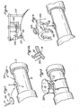
Sur la figure 1, on peut voir la partie de conduite 10 de laquelle a été retiré le calorifugeage 11 qui, en temps normal, protège thermiquement l'ensemble des circuits. La référence 12 désigne la zone où doit être implanté le piquage.In Figure 1, we can see the
Sensiblement au centre de cette zone est soudé le support de centrage d'outil 100 composé par exemple d'une tige 110 vissée au centre d'un plateau 120 à souder sur la paroi de la conduite.Significantly at the center of this zone is welded the
Au moyen d'un dispositif 200, l'opérateur mesure par ultrasons l'épaisseur de la conduite dans la zone à découper.By means of a
Il peut alors mettre en place (figure 2) la machine 300 de creusement de gorge, supportée par la tige 110. Cette machine est alors réglée pour usiner en profondeur la gorge 13 de manière à laisser un voile de métal 14 (visible figure 3b) de quelques dixièmes de millimètre d'épaisseur.It can then put in place (FIG. 2) the grooving
La figure 3a (avec le détail agrandi figure 3b) montre schématiquement la structure de cette machine : elle comprend un outil de découpe 310, par exemple une fraise cylindrique permettant de creuser la gorge. Il est prévu des moyens 330 de réglage de profondeur de cette fraise, la position de la surface de la conduite étant déterminée par exemple par un palpeur 320. Il est ainsi possible de suivre le surface de la conduite au voisinage de la fraise 310 sur tout le trajet de découpe, et bien que celui-ci suive un profil gauche (correspondant, dans le cas d'un piquage par tubulure circulaire, à l'intersection de deux cylindres). Il est également prévu des moyens 340 pour déplacer l'outil de découpe le long d'un tracé préétabli correspondant à la découpe à réaliser, par exemple un tracé circulaire, vu en plan.FIG. 3a (with the enlarged detail in FIG. 3b) schematically shows the structure of this machine: it comprises a
Une fois la gorge entièrement réalisée, l'opérateur retire la machine de perçage et met en place sur la conduite un organe d'isolation étanche apte à isoler l'orifice de l'atmosphère extérieure, une fois celui-ci réalisé. Cet organe d'isolation est par exemple constitué d'une boîte à gants permettant à l'opérateur de travailler librement tout en assurant l'isolation. Cette boîte à gants peut par exemple être assujettie à une embase gonflable 400 (figure 4) épousant la forme extérieure de la conduite et fixé à celle-ci au moyen de sangles 410. L'embase supporte une bride 420 permettant la fixation de la boite à gants. De préférence, l'embase est un joint gonflable par insufflation de gaz sous pression par la valve 430.Once the groove has been completely made, the operator withdraws the drilling machine and sets up on the pipe a sealed insulation member capable of isolating the orifice from the external atmosphere, once it has been made. This insulation member is for example made up of a glove box allowing the operator to work freely while providing insulation. This glove box can for example be subject to an inflatable base 400 (Figure 4) matching the external shape of the pipe and fixed to it by straps 410. The base supports a
La boîte à gants proprement dite 440 (figure 5) est ensuite fixée de manière étanche sur la bride 420. Il s'agit par exem- ple d'une enceinte de forme parallélépipédique ou cylindrique 450 en élastomère armé pourvue d'un sas 460 d'introduction des outils, de hublots 470 et de gants 480 pour l'opérateur.The actual glove 440 (Figure 5) is then sealingly attached to the
Dans cette boite à gants est introduit le dispositif récupérateur de débris 500 et le dispositif de défonçage final 600 (figure 6).In this glove box is introduced the
Le dispositif de récupération est par exemple celui décrit dans la demande française n° 83- au nom de la Demanderesse. Le dispositif décrit dans cette demande assure, une fois déployé à l'intérieur de la conduite en dessous de l'orifice, non seulement la récupération des copeaux et autres débris occasionnés par les opérations d'usinage sur cet orifice, mais encore l'étanchéité entre l'intérieur de la conduite et l'atmosphère extérieure. Il est ainsi possible de réaliser à l'air libre toutes opérations, y compris les soudures avec reprise envers, sur l'orifice ouvert dans la conduite.The recovery device is for example that described in French application No. 83- in the name of the Applicant. The device described in this application ensures, once deployed inside the pipe below the orifice, not only the recovery of chips and other debris caused by the machining operations on this orifice, but also the sealing between the inside of the pipe and the outside atmosphere. It is thus possible to carry out in the open air all operations, including welds with reverse flow, on the open opening in the pipe.
L'ouverture de cet orifice est réalisée par le dispositif de défonçage final 600 représenté figures 6a et 6b : ce dispositif soutenu et guidé par le support 100, comprend un gabarit de découpe 610 posé sur un support 620 prenant appui en totalité sur la zone de la paroi de la conduite située à l'extérieur de la zone définie par la gorge. Le gabarit comporte une rainure de guidage 630, au droit de la gorge, permettant de guider un outil de défonçage 640. Dans l'exemple représenté où il s'agit de pratiquer une ouverture circulaire, la rainure 630 est pratiquée sur une fraction de cercle , et l'opérateur fait tourner le gabarit 610 au fur et à mesure que les portions de circonférence sont défoncées.The opening of this orifice is carried out by the
Du fait de la très faible épaisseur du voile subsistant au fond de la gorge, le défonçage se fait sans production de copeaux (donc sans introduction de corps étrangers dans la conduite) et sans déformation de la paroi métallique de la conduite.Due to the very small thickness of the veil remaining at the bottom of the groove, the routing is done without producing chips (therefore without introduction of bodies foreigners in the pipe) and without deformation of the metal wall of the pipe.
Une fois le défonçage achevé, la fraction centrale de la paroi, découpée, reste retenue par la tige 110 du support d'outil ; en effet, cette tige reste reliée, par exemple par un écrou 650, au support 620 du dispositif de défonçage : on évite ainsi que, à la fin du défonçage, la fraction découpée ne tombe au fond de la conduite.Once the routing is complete, the central fraction of the wall, cut, remains retained by the
Au moment du démontage du dispositif de défonçage, l'opérateur retire cette fraction 12 par la tige 110, et introduit le dispositif récupérateur 500 à l'intérieur de la conduite, désormais ouverte.When disassembling the ripping device, the operator removes this
La figure 8 montre ce dispositif déployé à l'intérieur de la conduite: un joint gonflable 510, plaqué à l'intérieur de la conduite, autour de l'orifice,par un pied télescopique 520, assure la fixation étanche d'un voile souple 530 récupérant les débris et assurant l'isolation de l'intérieur de la conduite, qui peut être maintenu sous atmosphère contrôlée de gaz neutre.Figure 8 shows this device deployed inside the pipe: an
Un chanfrein 15 est ensuite pratiqué (figure 9) sur l'orifice pour permettre le soudage d'un manchon tubulaire 16 (figure 10) au moyen d'une torche 700, de manière classique.A
La soudure est observée, notamment sa partie envers au moyen d'un dispositif à miroirs 800 (figure 11), puis contrôlée par gammagraphie.The weld is observed, in particular its reverse side by means of a mirror device 800 (FIG. 11), then checked by radiography.
La boite à gants est alors remise en place, le dispositif récupérateur 500 retiré de la conduite (figure 12 ) et une calotte d'obturation 18 soudée à l'extrémité du manchon. Cette soudure est de préférence réalisée sans métal d'apport, par un dispositif à électrode réfractaire (soudage TIG).The glove box is then replaced, the
La boite à gants est alors retirée et le calorifugeage remis en place.The glove box is then removed and the insulation reinstalled.
La figure 13 montre une variante d'une machine de creusement de gorge , toujours dans le cas d'un perçage circulaire, dans laquelle l'outil de fraisage310 est supporté par une tige 331, de préférence une tige carrée interdisant toute rotation axiale. L'outil est amené en affleurement de la surface de la conduite par un vernier 332. C'est ensuite un vérin 330, par exemple un vérin double corps assurant une faible force de pression mais une précision importante, qui commandera la descente contrôlée de l'outil à la profondeur voulue. Un codeur 350 assure la transmission de l'information de profondeur au vérin 330.FIG. 13 shows a variant of a grooving machine, still in the case of a circular drilling, in which the
Un moteur 340, associé à un réducteur 341 entraînant le support 342 d'outil, entraîne celui-ci le long du tracé préétabli.A
L'ensemble de la machine peut par exemple être supporté par un bâti 360 fixé à la conduite 10 au moyen de sangles 370 entourant celle-ci.The whole machine can for example be supported by a
Les figures 14 et 15 montrent une autre possibilité d'outil de défonçage pour une ouverture circulaire : l'outil se compose alors d'un perforateur dentelé 660 mobile autour de la tige 110 soudée au centre de la zone à découper, par exemple au moyen d'une butée à billes 670. Il suffit alors à l'opérateur de placer ce perforateur au-dessus de la gorge 13 et d'effectuer de légères percussionssur celui-ci pour défoncer,sans production de copeaux,le voile de métal. La percussion peut être également remplacée par un système mécanique à vibreur.Figures 14 and 15 show another possibility of a routing tool for a circular opening: the tool then consists of a
Les figures 16 à 18 se réfèrent au perçage d'un trou non pas circulaire, mais rectangulaire en plan :
- les figures 16 et 17 montrent une variante de la machine de perçage. La gorge se composant de deux parties rectilignes et deux parties en forme d'arc de cercle, l'inclinaison de l'outil 310 par rapport à la surface de la conduite reste constante, ce qui en facilite le guidage pendant le suivi du tracé.
- Figures 16 and 17 show a variant of the drilling machine. The groove consisting of two rectilinear parts and two parts in the shape of an arc of a circle, the inclination of the
tool 310 relative to the surface of the pipe remains constant, which facilitates guiding during the tracking of the course.
La figure 18 montre un dispositif de défonçage pour découpe rectangulaire, analogue au dispositif des figures 6a et 6b prévu pour une gorge circulaire : le dispositif comporte également un gabarit 610' posé sur un socle 620'. La rainure 630' de guidage de l'outil 640 présente alors un profil rectiligne. La tige 110 du support d'outil assure comme précédemment le centrage des différentes pièces.Figure 18 shows a router for rectangular cutting device, similar to the device of Figures 6a and 6b provided for a circular groove: the device also includes a template 610 'placed on a base 620'. The
Claims (8)
Applications Claiming Priority (2)
| Application Number | Priority Date | Filing Date | Title |
|---|---|---|---|
| FR8304838 | 1983-03-24 | ||
| FR8304838A FR2543257B1 (en) | 1983-03-24 | 1983-03-24 | METHOD AND DEVICE FOR CREATING A PIPING IN A CONTROLLED ATMOSPHERE ON A PIPING SYSTEM, IN PARTICULAR A NUCLEAR POWER PLANT PIPING |
Publications (2)
| Publication Number | Publication Date |
|---|---|
| EP0120782A1 true EP0120782A1 (en) | 1984-10-03 |
| EP0120782B1 EP0120782B1 (en) | 1986-08-13 |
Family
ID=9287187
Family Applications (1)
| Application Number | Title | Priority Date | Filing Date |
|---|---|---|---|
| EP19840400585 Expired EP0120782B1 (en) | 1983-03-24 | 1984-03-22 | Method and apparatus for tapping a pipeline in a controlled atmosphere, particularly a nuclear plant pipeline |
Country Status (9)
| Country | Link |
|---|---|
| US (1) | US4573628A (en) |
| EP (1) | EP0120782B1 (en) |
| JP (1) | JPS6078194A (en) |
| AU (1) | AU561780B2 (en) |
| CA (1) | CA1224137A (en) |
| DE (1) | DE3460461D1 (en) |
| ES (1) | ES531212A0 (en) |
| FR (1) | FR2543257B1 (en) |
| ZA (1) | ZA842085B (en) |
Families Citing this family (12)
| Publication number | Priority date | Publication date | Assignee | Title |
|---|---|---|---|---|
| DE4137762A1 (en) * | 1991-11-16 | 1993-05-19 | Ruhrgas Ag | METHOD AND DEVICE FOR PRODUCING AN OPENING IN THE WALL OF A PIPELINE |
| DE19501951C1 (en) * | 1995-01-24 | 1996-05-09 | Diga Versorgungstechnik Holdin | Method of producing opening in pipe wall containing plastics inner pipe |
| US6024515A (en) * | 1996-03-04 | 2000-02-15 | Nicor Technologies Inc. | Live service pipe insertion apparatus and method |
| DE19918952C1 (en) * | 1999-04-27 | 2000-12-07 | Friteca Ag | Connection device |
| JP2003028375A (en) * | 2001-07-18 | 2003-01-29 | Ishikawajima Harima Heavy Ind Co Ltd | Pipe base attaching method, branched pipe connecting method, and dust antiscattering device |
| EP2414124B1 (en) * | 2009-03-31 | 2018-09-26 | Epic Applied Technologies, LLC | Method and apparatus of hot tapping multiple coaxial or nested strings of underwater piping and/or tubing for overturned wells or platforms |
| US20130056104A1 (en) | 2011-09-02 | 2013-03-07 | David J. Kriens, Jr. | Snap fitting for plumbing |
| JP6240526B2 (en) * | 2014-02-13 | 2017-11-29 | 日鉄住金パイプライン&エンジニアリング株式会社 | Mist scattering prevention device and blocking plug installation method |
| FR3030675B1 (en) * | 2014-12-18 | 2017-05-19 | Grdf | DEVICE AND METHOD FOR INTERVENTION ON A DERIVATION OF A FLUID DRIVE |
| US10408386B2 (en) * | 2015-08-21 | 2019-09-10 | Fab-Tech, Inc. | Hot tap system and method for coated ductwork |
| US10902958B2 (en) | 2018-04-03 | 2021-01-26 | Framatome Inc. | Mechanical seal assembly and method for sealing an opening in a nuclear power plant |
| CN116079099B (en) * | 2021-11-05 | 2023-11-24 | 国网安徽省电力有限公司利辛县供电公司 | Metal threading pipe inner wall processingequipment with regulatory function |
Citations (3)
| Publication number | Priority date | Publication date | Assignee | Title |
|---|---|---|---|---|
| GB184106A (en) * | 1921-11-16 | 1922-08-10 | South Metropolitan Gas Co | Improvements relating to devices for connecting a pipe to a main when under pressure |
| US3585699A (en) * | 1969-05-12 | 1971-06-22 | Eugene E Shuttle | Method of connecting subterranean pipe lines |
| US4234006A (en) * | 1979-01-11 | 1980-11-18 | Westinghouse Electric Corp. | Method of forming an opening in the outer enclosure of a gas-insulated electrical apparatus |
Family Cites Families (4)
| Publication number | Priority date | Publication date | Assignee | Title |
|---|---|---|---|---|
| US2050985A (en) * | 1934-01-29 | 1936-08-11 | Lock Joint Pipe Co | Method for tapping pipe |
| US3272211A (en) * | 1962-09-10 | 1966-09-13 | Mueller Co | Main and service line connection embodying a self-tapping nipple and an excessive-flow safety valve-method and apparatus |
| US3335742A (en) * | 1963-10-24 | 1967-08-15 | Trest Mosgazsetjstroi | Device for joining branches to operating gas or hydraulic pipelines |
| US3734112A (en) * | 1971-03-10 | 1973-05-22 | Mueller Co | Method of tapping a hole in a main through a fitting |
-
1983
- 1983-03-24 FR FR8304838A patent/FR2543257B1/en not_active Expired
-
1984
- 1984-03-20 US US06/591,405 patent/US4573628A/en not_active Expired - Fee Related
- 1984-03-21 ZA ZA842085A patent/ZA842085B/en unknown
- 1984-03-21 AU AU25966/84A patent/AU561780B2/en not_active Ceased
- 1984-03-22 DE DE8484400585T patent/DE3460461D1/en not_active Expired
- 1984-03-22 ES ES531212A patent/ES531212A0/en active Granted
- 1984-03-22 EP EP19840400585 patent/EP0120782B1/en not_active Expired
- 1984-03-23 CA CA000450430A patent/CA1224137A/en not_active Expired
- 1984-03-24 JP JP59057175A patent/JPS6078194A/en active Granted
Patent Citations (3)
| Publication number | Priority date | Publication date | Assignee | Title |
|---|---|---|---|---|
| GB184106A (en) * | 1921-11-16 | 1922-08-10 | South Metropolitan Gas Co | Improvements relating to devices for connecting a pipe to a main when under pressure |
| US3585699A (en) * | 1969-05-12 | 1971-06-22 | Eugene E Shuttle | Method of connecting subterranean pipe lines |
| US4234006A (en) * | 1979-01-11 | 1980-11-18 | Westinghouse Electric Corp. | Method of forming an opening in the outer enclosure of a gas-insulated electrical apparatus |
Also Published As
| Publication number | Publication date |
|---|---|
| DE3460461D1 (en) | 1986-09-18 |
| ES8504368A1 (en) | 1985-04-16 |
| US4573628A (en) | 1986-03-04 |
| CA1224137A (en) | 1987-07-14 |
| AU561780B2 (en) | 1987-05-14 |
| FR2543257B1 (en) | 1985-08-09 |
| ES531212A0 (en) | 1985-04-16 |
| FR2543257A1 (en) | 1984-09-28 |
| AU2596684A (en) | 1984-09-27 |
| EP0120782B1 (en) | 1986-08-13 |
| JPS6078194A (en) | 1985-05-02 |
| JPH0526999B2 (en) | 1993-04-19 |
| ZA842085B (en) | 1984-10-31 |
Similar Documents
| Publication | Publication Date | Title |
|---|---|---|
| EP0120782B1 (en) | Method and apparatus for tapping a pipeline in a controlled atmosphere, particularly a nuclear plant pipeline | |
| EP0158544B1 (en) | Process for replacing a sleeve inside a pipe, and devices for carrying out this process | |
| CH631791A5 (en) | METHOD AND DEVICE FOR MOUNTING A FLOW ADJUSTMENT ELEMENT IN A TUBULAR DUCT. | |
| EP0604265B1 (en) | Replacement nozzle and method for replacing a nozzle in a pressure vessel | |
| EP0596040B1 (en) | Device for cutting a pipe in order to stop a fluid flow | |
| FR2561962A1 (en) | METHOD AND DEVICE FOR PREPARING, WITH REMOTE HANDLING, THE TWO END OF A TUBE, FORMED BY SAWING A TUBE ELEMENT, OF A TUBULAR CONDUIT THUS SUBDIVIZED | |
| US2571916A (en) | Pipe-line device | |
| JP3474483B2 (en) | Piping structure, non-stop flow valve insertion method, gate valve and valve device for non-stop flow insertion | |
| EP0742562B1 (en) | Method for installing a sealed passage through a cell wall | |
| FR2561963A1 (en) | APPARATUS AND METHOD FOR ESTABLISHING ANOTHER PATH OF THE REFRIGERANT IN THE HEART OF A NUCLEAR REACTOR | |
| EP3987214B1 (en) | Apparatus for conducting a hydraulic proof test | |
| CN111482416B (en) | Scraping device for PE pipe and using method thereof | |
| EP0120783B1 (en) | Insulation and protection apparatus for intervention on a tube, especially a nuclear plant tube | |
| KR200393950Y1 (en) | Multifunction Polyethylene pipe Drill machine | |
| FR2607742A1 (en) | Method and appliance for piercing a pipeline for connection | |
| JP4173586B2 (en) | Resin pipe repair method and closure plug and tool used therefor | |
| JP2004100951A (en) | Piping structure, existing pipe cutting construction method, non-flow cutting-off valve insertion construction method, sluice valve element and non-flow cutting-off insertion valve device | |
| JP2019207011A (en) | Full-cut cutting method of fluid pipe, and full-cut cutting device | |
| EP2339220B1 (en) | Device for working on a gas pipe and corresponding method | |
| JP3035182B2 (en) | Equipment for cutting circumferential seal welds | |
| JP2024020169A (en) | Branch pipe forming device and method of attaching chip collector | |
| FR2697614A1 (en) | Machine for drilling holes in side of pipe filled with water - has housing with tool carrier and motor offset from shaft | |
| CA3182185A1 (en) | Sealing device for plugging a leak in the wall of a pipe or of a tank comprising a part for drilling and a part for tapping and sealing method | |
| JP2018179057A (en) | Piping blocking device and piping blocking method | |
| JP2003028375A (en) | Pipe base attaching method, branched pipe connecting method, and dust antiscattering device |
Legal Events
| Date | Code | Title | Description |
|---|---|---|---|
| PUAI | Public reference made under article 153(3) epc to a published international application that has entered the european phase |
Free format text: ORIGINAL CODE: 0009012 |
|
| AK | Designated contracting states |
Designated state(s): BE CH DE GB IT LI NL SE |
|
| 17P | Request for examination filed |
Effective date: 19841029 |
|
| GRAA | (expected) grant |
Free format text: ORIGINAL CODE: 0009210 |
|
| ITF | It: translation for a ep patent filed |
Owner name: CON LOR S.R.L. |
|
| AK | Designated contracting states |
Kind code of ref document: B1 Designated state(s): BE CH DE GB IT LI NL SE |
|
| REF | Corresponds to: |
Ref document number: 3460461 Country of ref document: DE Date of ref document: 19860918 |
|
| PLBE | No opposition filed within time limit |
Free format text: ORIGINAL CODE: 0009261 |
|
| STAA | Information on the status of an ep patent application or granted ep patent |
Free format text: STATUS: NO OPPOSITION FILED WITHIN TIME LIMIT |
|
| 26N | No opposition filed | ||
| PGFP | Annual fee paid to national office [announced via postgrant information from national office to epo] |
Ref country code: GB Payment date: 19930316 Year of fee payment: 10 |
|
| PGFP | Annual fee paid to national office [announced via postgrant information from national office to epo] |
Ref country code: CH Payment date: 19930317 Year of fee payment: 10 |
|
| PGFP | Annual fee paid to national office [announced via postgrant information from national office to epo] |
Ref country code: SE Payment date: 19930323 Year of fee payment: 10 |
|
| PGFP | Annual fee paid to national office [announced via postgrant information from national office to epo] |
Ref country code: DE Payment date: 19930324 Year of fee payment: 10 |
|
| ITTA | It: last paid annual fee | ||
| PGFP | Annual fee paid to national office [announced via postgrant information from national office to epo] |
Ref country code: NL Payment date: 19930331 Year of fee payment: 10 |
|
| PGFP | Annual fee paid to national office [announced via postgrant information from national office to epo] |
Ref country code: BE Payment date: 19930414 Year of fee payment: 10 |
|
| PG25 | Lapsed in a contracting state [announced via postgrant information from national office to epo] |
Ref country code: GB Effective date: 19940322 |
|
| PG25 | Lapsed in a contracting state [announced via postgrant information from national office to epo] |
Ref country code: SE Free format text: LAPSE BECAUSE OF NON-PAYMENT OF DUE FEES Effective date: 19940323 |
|
| PG25 | Lapsed in a contracting state [announced via postgrant information from national office to epo] |
Ref country code: LI Effective date: 19940331 Ref country code: CH Effective date: 19940331 Ref country code: BE Effective date: 19940331 |
|
| BERE | Be: lapsed |
Owner name: ELECTRICITE DE FRANCE SERVICE NATIONAL Effective date: 19940331 |
|
| PG25 | Lapsed in a contracting state [announced via postgrant information from national office to epo] |
Ref country code: NL Effective date: 19941001 |
|
| GBPC | Gb: european patent ceased through non-payment of renewal fee |
Effective date: 19940322 |
|
| NLV4 | Nl: lapsed or anulled due to non-payment of the annual fee | ||
| REG | Reference to a national code |
Ref country code: CH Ref legal event code: PL |
|
| PG25 | Lapsed in a contracting state [announced via postgrant information from national office to epo] |
Ref country code: DE Effective date: 19941201 |
|
| EUG | Se: european patent has lapsed |
Ref document number: 84400585.0 Effective date: 19941010 |