EP0120719A1 - Nicht implantierter magnetischer Blasenspeicher und sein Steuerverfahren - Google Patents
Nicht implantierter magnetischer Blasenspeicher und sein Steuerverfahren Download PDFInfo
- Publication number
- EP0120719A1 EP0120719A1 EP84400095A EP84400095A EP0120719A1 EP 0120719 A1 EP0120719 A1 EP 0120719A1 EP 84400095 A EP84400095 A EP 84400095A EP 84400095 A EP84400095 A EP 84400095A EP 0120719 A1 EP0120719 A1 EP 0120719A1
- Authority
- EP
- European Patent Office
- Prior art keywords
- bubbles
- bubble
- bubble memory
- memory according
- contraction
- Prior art date
- Legal status (The legal status is an assumption and is not a legal conclusion. Google has not performed a legal analysis and makes no representation as to the accuracy of the status listed.)
- Granted
Links
- 230000015654 memory Effects 0.000 title claims abstract description 81
- 238000000034 method Methods 0.000 title claims abstract description 17
- 239000004020 conductor Substances 0.000 claims description 73
- 238000001514 detection method Methods 0.000 claims description 20
- 230000008602 contraction Effects 0.000 claims description 16
- 230000005415 magnetization Effects 0.000 claims description 8
- 238000003860 storage Methods 0.000 claims description 6
- 239000000696 magnetic material Substances 0.000 claims description 5
- 230000008520 organization Effects 0.000 description 16
- 244000309464 bull Species 0.000 description 9
- 239000000463 material Substances 0.000 description 9
- XEEYBQQBJWHFJM-UHFFFAOYSA-N Iron Chemical compound [Fe] XEEYBQQBJWHFJM-UHFFFAOYSA-N 0.000 description 8
- PXHVJJICTQNCMI-UHFFFAOYSA-N Nickel Chemical compound [Ni] PXHVJJICTQNCMI-UHFFFAOYSA-N 0.000 description 8
- 230000015572 biosynthetic process Effects 0.000 description 7
- 238000006073 displacement reaction Methods 0.000 description 6
- 230000006870 function Effects 0.000 description 6
- 230000006911 nucleation Effects 0.000 description 6
- 238000010899 nucleation Methods 0.000 description 6
- 229910052742 iron Inorganic materials 0.000 description 4
- 229910052759 nickel Inorganic materials 0.000 description 4
- 241001347978 Major minor Species 0.000 description 3
- 230000001066 destructive effect Effects 0.000 description 3
- 239000002223 garnet Substances 0.000 description 3
- 230000002457 bidirectional effect Effects 0.000 description 2
- 239000000470 constituent Substances 0.000 description 2
- 238000010586 diagram Methods 0.000 description 2
- 239000010432 diamond Substances 0.000 description 2
- 238000005468 ion implantation Methods 0.000 description 2
- 238000004519 manufacturing process Methods 0.000 description 2
- 230000009471 action Effects 0.000 description 1
- 238000005520 cutting process Methods 0.000 description 1
- 230000000694 effects Effects 0.000 description 1
- 150000002500 ions Chemical class 0.000 description 1
- 230000005381 magnetic domain Effects 0.000 description 1
- 230000000644 propagated effect Effects 0.000 description 1
- 239000000758 substrate Substances 0.000 description 1
- 230000009466 transformation Effects 0.000 description 1
Images


Classifications
-
- G—PHYSICS
- G11—INFORMATION STORAGE
- G11C—STATIC STORES
- G11C19/00—Digital stores in which the information is moved stepwise, e.g. shift registers
- G11C19/02—Digital stores in which the information is moved stepwise, e.g. shift registers using magnetic elements
- G11C19/08—Digital stores in which the information is moved stepwise, e.g. shift registers using magnetic elements using thin films in plane structure
- G11C19/0866—Detecting magnetic domains
-
- G—PHYSICS
- G11—INFORMATION STORAGE
- G11C—STATIC STORES
- G11C19/00—Digital stores in which the information is moved stepwise, e.g. shift registers
- G11C19/02—Digital stores in which the information is moved stepwise, e.g. shift registers using magnetic elements
- G11C19/08—Digital stores in which the information is moved stepwise, e.g. shift registers using magnetic elements using thin films in plane structure
- G11C19/0875—Organisation of a plurality of magnetic shift registers
- G11C19/0883—Means for switching magnetic domains from one path into another path, i.e. transfer switches, swap gates or decoders
Definitions
- the present invention relates to a magnetic bubble memory with non-implanted patterns and its control method.
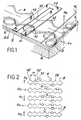
- FIG. 1 part of a memory with magnetic bubbles has been shown.
- This memory comprises a monocrystalline magnetic layer 2 such as a magnetic garnet film supported by a non-magnetic monocrystalline garnet 4.
- this layer 2 it is possible to create domains of magnetic bubbles such as 6.
- These magnetic bubbles can be stabilized by application of a continuous magnetic field Hp perpendicular to the plane of the magnetic layer 2.
- this magnetic field is created by a permanent magnet thus ensuring the non-volatility of the information contained in the memory.
- the displacement of the bubbles 6 is carried out by applying a rotating continuous field H, r , directed in a direction parallel to the surface of the magnetic layer 2.
- the displacement of the bubbles takes place around so-called propagation patterns 8, defined in the upper part 2a of the magnetic layer 2.
- These patterns 8 having the shape of circles, ellipses, diamonds, triangles, polygons, etc. can be made of a material based on iron and nickel, or else obtained by implanting ions in the upper part 2a of the magnetized layer tick, through a mask to define the shape of these patterns. In the latter case, since the ion implantation is carried out only around the patterns, these patterns are called non-implanted patterns.
- the propagation patterns are generally contiguous and have identical shapes and dimensions. Because of their shape, for example diamonds as shown in FIG. 1, two adjacent patterns delimit between them two cavities or hollows 10. These patterns also include vertices or points 12.
- the displacement of the magnetic bubbles 6 has been shown under the action of the rotating magnetic field H T.
- the displacement of the bubbles along these patterns 8 is generally done for a duration equal to one third of the period of rotation of the plane magnetic field H T , the bubbles remaining immobile in the cavities 10 defined between two adjacent patterns, during the rest of the cycle.
- Shift registers have thus been produced in which the binary information "1" is represented by the presence of a bubble and the binary information "0" by the absence of a bubble.
- the displacement made by the magnetic bubbles during a period of rotation of the field is generally called a step, it represents for example the distance P separating two vertices 12 from two contiguous patterns 8.
- these electrical conductors In addition to these propagation patterns, it is necessary to use electrical conductors to perform writing, non-destructive reading, transfer from register to register and erasure in the bubble memory. As shown in FIG. 1, these electrical conductors such as 14 "pass through" the propagation patterns 8. These conductors 14 are arranged in particular on a dielectric layer 16 located above the material layer 2.
- One of the main types of magnetic bubble memory known comprises a set of loops, or registers, called minor used for the storage of information, associated with one or two loops, or registers, called major, constituting the memory access stations.
- the minor loops are arranged longitudinally, one next to the other and the major loops are oriented perpendicular to the minor loops.
- the magnetic bubbles in the minor loops can be transferred to the major loops and vice versa, via unidirectional or bidirectional transfer gates.
- the manufacture of a bubble on a major loop is carried out by applying a high current to a conductor, generally in the shape of a U (FIG. 1 ), crossing the propagation patterns constituting the major loop.
- This operation generally known as nucleation name is performed when the bubble is in a cavity defined between two adjacent patterns.
- the bubble is then propagated, by applying the rotating field " T , over the major loop to the transfer gates in order to transfer the bubble from the major loop to a minor loop.
- These transfer gates are generally produced by a conductor U-shaped. The application of a current pulse to this conductor makes it possible to extend each bubble between the vertices of the propagation patterns of the major loop and those corresponding to the minor loop and then, stopping the current pulse causes the bubbles on the minor loop to contract and transfer is carried out, thereby storing information on the minor loop.
- This information is read by transferring a magnetic bubble from a minor loop to a major loop. The transfer is done as before.
- the corresponding bubble must be duplicated.
- this duplication is carried out by means of a conductor ( Figure 1) crossing the major loop, to which a current pulse is applied, causing the elongation of the bubble on both sides. another of the propagation paths, then cutting this bubble in half.
- a conductor Figure 1
- Figure 1 One of these bubbles, transferred to a detection path, can be detected destructively by a magneto-resistive type detector, generally based on iron and nickel, and the other bubble will be re-injected into the loop minor in the place occupied by the original bubble.
- Magnetic bubble memories comprising, as propagation patterns, non-implanted patterns and having a structure and functioning such as those described above (see American patent), have two important limitations which are the time of access to information and the speed some information.
- one solution consists in dividing the bubble memory into several similar devices or memory elements operating in parallel on the same chip; these independent devices or elements have any organization, for example a parallel series organization or a major-minor organization.
- the data rate which is proportional to the number of memory detectors, is then increased and the information access time reduced since the memory area of each device is reduced.
- Such a memory structure is described in an article by P.K. GEORGE, H.S. GILL, R.H. NORTON, G.F. REYLING, A.M. TUXFORD published in Intermag ConfInter Digest, GRENOBLE 1971, Paper n ° 9-1.
- this organization or structure of the memory requires a number of control circuits proportional to the number of devices or memory elements contained in the chip and especially with regard to the multiplicity of bulb detection circuits the ; the use of several control circuits considerably increases the cost of manufacturing the memory.
- the object of the present invention is precisely a memory with magnetic bubbles using, as the propagation patterns of the bubbles, non-implanted patterns making it possible to remedy the drawbacks given above.
- the invention relates to a bubble memory comprising, electrically connected to each other, 3n similar memory devices produced on the same circuit chip, n being a positive integer, and each comprising minor loops used for storage.
- bubbles at least one major loop serving as an access loop to the minor loops, first electrical means allowing the transfer of the bubbles from the minor loops to the major loop and vice versa, a second electrical means making it possible to generate bubbles on the loop major and a third electrical means making it possible to detect the bubbles on the major loop, the third means, identical and each consisting of an electrical conductor for extension-contraction of the bubbles and by a magneto-resistive element, being arranged in directions forming between they an angle of 120 °.
- the number of memory devices is 6n and the third means are arranged in directions forming an angle of 60 ° between them.
- the result of this assembly and in particular of the orientation of the bubble detection means is a bubble memory whose organization is identical to that of bubble memories comprising a single memory device but which comprises, if N is the number of memory devices, N times more minor loops and N times more major loops and whose data rate is N times greater than those of bubble memories with a single memory device.
- the bubbles which propagate on the major loops are spaced one, two or four steps apart from each other; one step corresponds to a period of rotation of the rotating field to which the magnetic bubbles are subjected.
- These memory devices can also include a fourth electrical means making it possible to duplicate the magnetic bubbles, these fourth means being identical and arranged in the same direction.
- the memory devices are three or six in number.
- the second means are electrically connected to each other and in series.
- the electrical conductors for bubble expansion-contraction and the magneto-resistive elements of the third means are electrically connected to each other and in series.
- the invention also relates to a method for controlling the various electrical means constituting the bubble memory as defined above.
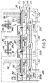
- FIG 3 there is shown a block diagram of a bubble memory according to the invention.
- the various elements (conductors, propagation patterns) forming part of the memory have been represented in the same plane.
- This bubble memory comprises 3n or 6n similar memory devices, n being a positive integer. Preferably these devices are three or six in number (n being equal to 1).
- Each memory device 20a, 20b or 20c comprises several minor loops 22 serving for the storage of the magnetic bubbles, not shown. These minor loops 22 are all arranged one next to the other. These three devices of the same structure, include in particular the same number of minor loops 22, as shown in FIG. 3. With these minor loops 22 is associated, for each memory device, a single major loop 24 serving as an access loop to the minor loops 22. This major loop 24 which is oriented perpendicular to the corresponding minor loops 22 is used both for writing and for reading information.
- the different arrows f shown illustrate the direction of propagation of the magnetic bubbles in the memory.
- the transfer doors 26 of the three memory devices 20a, 20b and 20c are electrically connected to each other; the connection of these different doors is provided by the conductor 28. They can be connected in series, as shown in Figure 3, or in parallel. In addition, these transfer doors are identical and arranged in the same direction.
- the transfer of the magnetic bubbles, by means of the transfer doors 26, is ensured by applying to these doors identical currents, that is to say the same current pulse.
- This current pulse is applied simultaneously to all transfer gates of all memory devices so as to effect transfer simultaneously on all of these devices.
- This current pulse can have either a single amplitude level or several amplitude levels of the same signs or opposite signs.
- each memory device 20a, 20b or 20c comprises a conductor 30 making it possible to split or duplicate the magnetic bubbles.
- This duplication is generally carried out in order to read the information contained in the minor loops 22. The reading of information is done by extracting magnetic bubbles from the minor loops 22, by means of transfer doors 26. These bubbles are then routed to conductor 30 in order to be duplicated.
- One of the bubbles obtained by duplication will be sent, by the propaga path tion 24a, on the minor loop 22 in the place occupied by the original bubble and the other bubble will be routed by the propagation path 24b in order to be detected destructively.
- Each duplication conductor 30, located at the level of the corresponding major loop 24, has for example the shape of a U (see enlarged part B of the figure).
- the duplication conductors 30 of the three memory devices 20a, 20b 20c are electrically connected to each other; the connection of the three duplication conductors 30 is ensured by the conductor 32.
- These conductors can be connected in series, as shown in FIG. 3, or else in parallel. In addition, they are identical and oriented in the same direction.
- the duplication of the magnetic bubbles, by means of the conductors 30, is ensured by applying to these conductors identical currents, that is to say the same current pulse.
- This current pulse is applied simultaneously to the three conductors 30 so as to perform simultaneous duplication on the three devices.
- This current pulse can have either a single amplitude level or several amplitude levels of the same signs or opposite signs.
- duplication conductors 30 are the same, whatever the number, 3n or 6n and preferably three or six, of memory devices constituting the memory according to the invention.
- Each memory device 20a, 20b or 20c further comprises a generator of magnetic bubbles 34a, 34b or 34c operating in particular on the principle of nucleation.
- Each generator or nucleator located at the corresponding major loop 24, consists of an electrical conductor to which electrical pulses can be applied, causing bubbles to form.
- the generators 34a, 34b and 34c are electrically connected together and preferably in series, the connection of these three generators being ensured by the conductor 36.
- Each memory device 20a, 20b or 20c further comprises a magnetic bubble detector 38a, 38b or 38c operating on the principle of destructive detection.
- Each detector located at the corresponding major loop 24, consists in particular of an electrical conductor, said extension-contraction conductor, and of a conductive element preferably magneto-resistive based on iron and nickel. When the latter is traversed by a direct current, the application of current pulses on the corresponding extension-contraction conductor causes the detection of bubbles.
- the detectors 38a 38b and 38c, respectively of the three memory devices 20a, 20b and 20c are electrically connected to each other and preferably in series; the connection of the extension-contraction conductors is carried out by the conductor 40 and the connection of the magneto-resistive conductive elements by the conductor 42.
- Such a memory organization of course applicable to a memory comprising six arrangements similar memory, increases the speed of information. Furthermore, this memory requires for its operation the same number of electrical conductors, such as conductors 28, 32, 36, 40 and 42, as a bubble memory consisting of a single memory device requires.
- the bubbles which propagate on the major loops are spaced from one another by one, two or four steps, a magnetic bubble making one step during a period of rotation of the rotating magnetic field H T.
- FIG. 4 the organization of the magnetic bubble generators has been represented, in the case of three generators, therefore of a bubble memory comprising three memory devices 20a, 20b and 20c (FIG. 3).
- the generators, respectively 34a, 34b and 34c, are constituted by electrical conductors which may each have an axis of symmetry, respectively 44a, 44b and 44c. These conductors, having in particular the shape of a U, are electrically connected to each other, and preferably in series, by conductor 36.
- This figure also shows the contiguous non-implanted propagation patterns 4.6 of the corresponding major loops 24 (FIG. 3), located at the level of each generator.
- the generation of magnetic bubbles 48 is distinguished on each memory device 20a, 20b or 20c by the orientation of the generators 34a, 34b and 34c.
- the generation of magnetic bubbles, by means of the generators, can only be done if there is a relationship between the phase of the electric pulse applied to the generators and the orientation of these generators; the phase of the pulse is the phase of the magnetic field H T when the said pulse is applied. This is achieved using generators with a narrow phase tolerance or tolerance. This phase margin is + 20 °.
- the three generators 34a, 34b and 34c are identical and oriented in directions making between them angles of 120 °.
- these three axes form an angle of 120 ° between them.
- These axes of symmetry can for example be directed along the three equivalent coplanar crystallographic axes, of easy magnetization, of the layer of magnetic material 50 forming between them an angle of 120 °.
- the three crystalline axes graphics include the axes 112, 121 and 211, as shown at the bottom right of the figure.
- This signal comprises several current pulses, for example having a single amplitude level and making it possible to successively control the three generators. As shown in FIG.
- the formation of magnetic bubbles, by means of the three generators, is preferably carried out from the vertices 49 of the propagation patterns 46 associated with each generator.
- the six identical generators are grouped into two groups of three generators, the two groups being electrically connected in series.
- the generators of the same group are connected and oriented as shown in the figure 4, that is to say so that the three axes of symmetry of the electrical conductors constituting these generators make between them an angle of 120 °.
- These axes of symmetry can in particular be directed along the equivalent coplanar crystallographic axes, of easy magnetization (112, 121, 211), of the layer of material containing the magnetic bubbles.
- This signal comprises several current pulses, having a single amplitude level and making it possible to successively control the six generators. As shown in FIG.
- the two groups of generators are controlled alternately and the current pulses, applied to the three generators of the same group, are of opposite polarity to those applied to the three generators of the other group; the pulses 54a, 54b, 54c, of the same polarity, are applied respectively to the three magnetic bubble generators, for example 34a, 34b and 34c (FIG. 4), belonging to the same group and the pulses 54d, 54e, 54f, of reverse polarity to that of pulses 54a, 54b and 54c, are applied respectively on the three generators of the other group.
- the formation of the magnetic bubbles is preferably carried out from the vertices 49 of the propagation patterns 46 associated with each generator (FIG. 4).
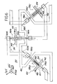
- the detectors 38a, 38b and 38c each consist of an electrical extension-contraction conductor respectively 56a, 56b and 56c having in particular the shape of a U, and of a conductive element of magneto-resistive type respectively 58a, 58b and 58c .
- the extension-contraction conductors are electrically connected to each other, and preferably in series, by means of the conductor 40 and the magneto-resistive elements are electrically connected to each other, and preferably in series, by means of the conductor 42.
- These detectors 38a, 38b and 38c may each have an axis of symmetry respectively 60a, 60b, 60c. These axes correspond both to the axes of symmetry of the extension-contacting conductors and to the axes of symmetry of the magneto-resistive elements.
- This figure also shows the non-implanted propagation patterns 46 of the corresponding major loops 24 (FIG. 3), located at the level of each detector, as well as the magnetic bubbles 48 which move along these patterns.
- the detectors 38a, 38b and 38c are distinguished from one another by their orientation on the corresponding memory devices.
- the three detectors 38a, 38b and 38c are identical and oriented in directions making between them angles of 120 °.
- these detectors have axes of symmetry 60a, 60b and 60c respectively, these three axes form an angle of 120 ° between them.
- the destructive detection of a magnetic bubble consists in first of all lengthening the bubble, by electrically exciting the extension-contraction conductor, then in detecting the bubble, using the magneto- element. resistive traversed by a constant current and to contract the bubble, electrically exciting the extension-contraction conductor.
- the detection of a magnetic bubble by the magneto-resistive element corresponds to the transformation of this bubble into an electrical signal. After the bubble has contracted, it can be annihilated or sent back towards the minor curls.
- the propagation patterns 46 located opposite each detector 38a, 38b or 38c can be aligned along an axis 43, parallel to one of the equivalent, easily magnetized, coplanar crystallographic axes of the layer of material 50 containing the propagation patterns 46. As shown in FIG. 6, these three crystallographic axes can be, for example, axes Il2, 121 and 211 for a layer of material 50, epitaxially grown in a direction 111.
- the alignment axis 43 of the propagation patterns is generally disposed in a direction perpendicular to the axis of symmetry 60a, 60b or 60c of the corresponding detector, it follows that these axes of symmetry are oriented perpendicularly to said coplanar crystallographic axes, of easy magnetization.
- the extension of the magnetic bubbles 48 is done from one of the cavities 47, delimited between two adjacent patterns 46, as shown in FIG. 6.
- the axis of symmetry 60a, 60b or 60c detectors associated with these propagation patterns passes through the two cavities delimited by two corresponding adjacent patterns.
- Another solution consists, as shown in FIG. 7, in extending the magnetic bubbles 48 from one of the vertices 49 of the propagation patterns 46 associated with each detector. In this case, it does not matter the orientation of the propagation patterns with respect to the crystallographic axes, of easy magnetization, of the layer of material containing said propagation patterns.
- the detection of magnetic bubbles by means of the three detectors 38a, 38b and 38c is ensured by applying the same electrical signal to the three extension -contraction conductors constituting them, the magneto-resistive elements being supplied with direct current.
- This signal comprises several current pulses making it possible to successively excite the three extension-contraction conductors.
- the actual detection of bubbles by means of the three magneto-resistive elements is also carried out successively by said elements.
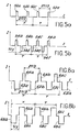
- the control of a detector notably consists in applying to the extension-contraction conductor the constituent two pulses of currents, having for example the same amplitude but having opposite polarities. They can have different or identical durations.
- FIG. 8a shows the amplitude of the current pulses I as a function of time t.
- the current pulses 62a, 62b and 62c, of the same polarity, applied respectively to the three extension-contraction conductors 56a, 56b, 56c make it possible to lengthen the magnetic bubbles 48 to be detected over a length of approximately 100 ⁇ in the spaces provided for this purpose.
- the pulses 64a, 64b and 64c, of opposite polarity to that of the pulses 62a, 62b and 62c, applied respectively to the three extension-contraction conductors 56a, 56b and 56c make it possible to contract the magnetic bubbles 48 previously elongated.
- the current pulses 64a, 64b and 64c, relating to the contraction of the bubbles exciting the three extension-contraction conductors are spaced from each other by a time equal to q / 3 rotation period T of the magnetic field turning H T , q being the number of steps separating the magnetic bubbles 48 from each other on the major loops 24.
- the time separating the pulses relating to the elongation of the bubbles and those relating to the contraction of the bubbles can be arbitrary.
- the magneto-resistive elements As regards the detection itself, by means of the magneto-resistive elements, this is carried out by applying a direct current to the three elements connected in series. The presence of a bubble in one of the detectors causes the resistance of the magneto-resistive element to vary. The resulting electrical signal appears only in a portion of the rotation cycle of the rotating field H, l. This detection is carried out successively on the three magneto-resistive elements. The detection signals relating to the three elements 58a, 58b and 58c are spaced from each other by a time equal to q / 3 period of rotation T of the rotating field H T. The use of magneto-resistive elements based on iron and nickel facilitates the detection of magnetic bubbles since these elements have a good signal / noise ratio and low impedance; this notably facilitates their connection in series (FIG. 6).
- the six identical detectors are grouped into two groups of three detectors, the two groups being electrically connected in series; in other words the two groups of extension-contraction conductors on the one hand, and the two groups of magneto-resistive elements on the other hand, are connected in series.
- the detectors of the same group are connected and oriented as shown in FIG. 6, that is to say so that the three axes of symmetry of these detectors make an angle of 120 ° between them.
- the two groups of detectors are oriented relative to each other so that the six axes of symmetry make an angle of 60 ° between them.
- the six axes of symmetry can for example be directed perpendicular to the three equivalent coplanar crystallographic axes, of easy magnetization, of the layer of material 50 containing the reasons for propagation; in other words the axes of alignment of the propagation patterns, located opposite each detector can be oriented parallel to said crystallographic axes, the alignment axes being perpendicular to the axes of symmetry of the corresponding detectors.
- the crystallographic axes may in particular be the axes 112, 121 and 211 for a layer of material epitaxially grown in a direction 111. In such an arrangement of the detectors, the extension of the magnetic bubbles takes place, as in the case of three detectors, from of one of the cavities, delimited between two adjacent patterns ( Figure 6).
- the extension of the magnetic bubbles can also take place from one of the vertices of the propagation patterns associated with each detector ( Figure 7), to avoid the nucleation problem, whatever the orientation. of these patterns with respect to said crystallographic axes.
- the detection of magnetic bubbles is ensured as previously by applying the same electrical signal to the six extension-contraction conductors constituting them, the magneto-resistive elements being supplied with direct current.
- This signal comprises a plurality of current pulses for driving successi - vely six conductors extension-contraction.
- the actual detection of bubbles by means of the six magneto-resistive elements is also carried out successively by said elements.
- the control of a detector consists in applying to the extension-contraction conductor the constituent two current pulses, having in particular the same amplitude but having opposite polarities.
- the pulses 66a, 66b and 66c are applied respectively to the extension-contraction conductors, for example 56a, 56b and 56c (FIG. 6), belonging to the same group of detectors, to allow the elongation of the magnetic bubbles 48 to be detected using these detectors.
- These same pulses are applied respectively to the extension-contraction conductors belonging to the other group of detectors to allow the contraction of other magnetic bubbles.
- the pulses 68a, 68b and 68c are applied respectively to the extension-contraction conductors, for example 56a, 56b and 56c (FIG. 6), belonging to the same group of detectors, to allow the contraction of previously elongated magnetic bubbles 48.
- the extension-contraction conductors belonging to the other group of detectors, to allow the elongation of other magnetic bubbles.
- the detectors must be designed so that the amplitude and duration of the elongation of the magnetic bubbles are equal to respectively the amplitude and duration of the con - traction of these bubbles. It follows that the current pulses used for the elongation of the bubbles, and the current pulses, used for the contraction of these bubbles, must have the same amplitude and the same duration, as shown in FIG. 8b.
- the current pulses relating to the extension of the bubbles, respectively exciting the three extension conductors-con traction of the same group of detectors, are spaced from each other by a time equal to q / 3 period of rotation T of the rotating magnetic field AND, when the magnetic bubbles 48 are spaced from each other by q not on the major loops 24.
- the same is true for the current pulses relating to the contraction of the bubbles, respectively exciting the three extension-contraction conductors of the same group.
- the magneto-resistive elements As regards the actual detection, by means of the magneto-resistive elements, this is carried out as previously, that is to say successively on the six elements.
- the detection signals relating to the three elements of the same group are spaced from each other by a time equal to q / 3 period of rotation of the field, that is to say that the detection signals relating to the six elements are spaced from each other by a time equal to q / 6 period of rotation of said field.
- the magnetic bubble memory with non-implanted patterns and its control method, as described above, make it possible to considerably increase the speed of the information contained in the memory compared to the bubble memories of the prior art.
Landscapes
- Thin Magnetic Films (AREA)
- Hall/Mr Elements (AREA)
Applications Claiming Priority (2)
| Application Number | Priority Date | Filing Date | Title |
|---|---|---|---|
| FR8300866 | 1983-01-20 | ||
| FR8300866A FR2539909B1 (fr) | 1983-01-20 | 1983-01-20 | Memoire a bulles magnetiques a motifs non implantes et son procede de commande |
Publications (2)
| Publication Number | Publication Date |
|---|---|
| EP0120719A1 true EP0120719A1 (de) | 1984-10-03 |
| EP0120719B1 EP0120719B1 (de) | 1987-09-30 |
Family
ID=9285139
Family Applications (1)
| Application Number | Title | Priority Date | Filing Date |
|---|---|---|---|
| EP84400095A Expired EP0120719B1 (de) | 1983-01-20 | 1984-01-17 | Nicht implantierter magnetischer Blasenspeicher und sein Steuerverfahren |
Country Status (5)
| Country | Link |
|---|---|
| US (1) | US4525807A (de) |
| EP (1) | EP0120719B1 (de) |
| JP (1) | JPS59142794A (de) |
| DE (1) | DE3466611D1 (de) |
| FR (1) | FR2539909B1 (de) |
Cited By (1)
| Publication number | Priority date | Publication date | Assignee | Title |
|---|---|---|---|---|
| EP0296665B1 (de) * | 1987-06-18 | 1995-09-06 | New Holland Belgium N.V. | Rundballenpresse mit Rollen und Riemen |
Families Citing this family (1)
| Publication number | Priority date | Publication date | Assignee | Title |
|---|---|---|---|---|
| FR2582436B1 (fr) * | 1985-05-21 | 1989-09-15 | Commissariat Energie Atomique | Generateur de bulles magnetiques pour memoire a bulles en technologie hybride |
Citations (1)
| Publication number | Priority date | Publication date | Assignee | Title |
|---|---|---|---|---|
| GB2094082A (en) * | 1981-01-19 | 1982-09-08 | Philips Nv | A device for the storage of digital information in the form of magnetic bubbles |
Family Cites Families (5)
| Publication number | Priority date | Publication date | Assignee | Title |
|---|---|---|---|---|
| JPS597146B2 (ja) * | 1978-01-06 | 1984-02-16 | 株式会社日立製作所 | 磁気バブル装置 |
| US4253159A (en) * | 1979-12-03 | 1981-02-24 | Bell Telephone Laboratories, Incorporated | Ion-implanted bubble memory with replicate port |
| JPS56117385A (en) * | 1980-02-18 | 1981-09-14 | Nec Corp | Magnetic bubble memory device |
| US4387443A (en) * | 1980-04-14 | 1983-06-07 | Agency Of Industrial Science And Technology | Magnetic bubble device |
| JPS6038796B2 (ja) * | 1982-09-14 | 1985-09-03 | 電子計算機基本技術研究組合 | コンテイギユアスデイスク型磁気バブル素子 |
-
1983
- 1983-01-20 FR FR8300866A patent/FR2539909B1/fr not_active Expired
-
1984
- 1984-01-17 DE DE8484400095T patent/DE3466611D1/de not_active Expired
- 1984-01-17 US US06/571,484 patent/US4525807A/en not_active Expired - Fee Related
- 1984-01-17 EP EP84400095A patent/EP0120719B1/de not_active Expired
- 1984-01-20 JP JP59007417A patent/JPS59142794A/ja active Pending
Patent Citations (1)
| Publication number | Priority date | Publication date | Assignee | Title |
|---|---|---|---|---|
| GB2094082A (en) * | 1981-01-19 | 1982-09-08 | Philips Nv | A device for the storage of digital information in the form of magnetic bubbles |
Cited By (1)
| Publication number | Priority date | Publication date | Assignee | Title |
|---|---|---|---|---|
| EP0296665B1 (de) * | 1987-06-18 | 1995-09-06 | New Holland Belgium N.V. | Rundballenpresse mit Rollen und Riemen |
Also Published As
| Publication number | Publication date |
|---|---|
| FR2539909B1 (fr) | 1985-06-07 |
| EP0120719B1 (de) | 1987-09-30 |
| DE3466611D1 (en) | 1987-11-05 |
| JPS59142794A (ja) | 1984-08-16 |
| US4525807A (en) | 1985-06-25 |
| FR2539909A1 (fr) | 1984-07-27 |
Similar Documents
| Publication | Publication Date | Title |
|---|---|---|
| EP1225593B1 (de) | Magnetische Anordnung basiert auf Spinpolarisierung und Rotationsmagnetisierung, Speicher und Schreibverfahren unter Verwendung einer solcher | |
| EP1506581B1 (de) | Supraleitende quanten-bit-einrichtung mit josephson-übergängen | |
| EP0340085B1 (de) | Magnetkopf-Matrixanordnung, insbesondere aus Dünnfilmen | |
| EP0010494B1 (de) | Verfahren zum Informationsschreiben auf einen magnetischen Aufzeichnungsträger | |
| EP0012649B1 (de) | Magnetischer Lesekopf | |
| EP0120719B1 (de) | Nicht implantierter magnetischer Blasenspeicher und sein Steuerverfahren | |
| EP0369839A1 (de) | Magnetischer Kopf mit sättigbarem Spalt und Matrixanordnung bestehend aus einem Satz mit solchen Köpfen | |
| EP0028177B1 (de) | Integrierter Magnetwandler | |
| EP0102257B1 (de) | Magnetblasenspeicher mit nicht-implantierten Mustern und seine Anwendung zum binärweisen und blockweisen Duplizieren der Binärelemente | |
| EP0295979B1 (de) | Verfahren zur Aufzeichnung von Information auf einem magnetischen Aufzeichnungsträger | |
| EP0038754A1 (de) | Magnetischer Blasenspeicher | |
| EP0130128B1 (de) | Magnetische Blasenspeicher | |
| EP0125154B1 (de) | Magnetische Blasenspeicher | |
| FR2562706A1 (fr) | Duplicateur dans une memoire a bulles a motifs non implantes, procede pour la mise en oeuvre dudit duplicateur et memoire a bulles de type serie-parallele comportant au moins un desdits duplicateurs | |
| EP0238370B1 (de) | Magnetischer Blasenspeicher in hybrider Technologie | |
| EP0161160A1 (de) | Austauschgatter für einen magnetischen Blaserspeicher mit nichtimplantierten Mustern und magnetischer Blasenspeicher vom serienparallelen Typ mit mindestens einem solchen Austauschgatter | |
| EP0038755A1 (de) | Magnetischer Blasenspeicher | |
| EP0203849B1 (de) | Magnetischer Blasengenerator für einen Blasenspeicher in hybrider Technologie | |
| CH486094A (fr) | Dispositif de mémoire de données | |
| FR2604281A1 (fr) | Procede et dispositif pour detecter la presence de lignes de bloch dans une paroi magnetique et memoire a lignes de bloch | |
| JPS5911983B2 (ja) | バブル磁区ジエネレ−タ | |
| FR2618013A1 (fr) | Procede pour transferer des lignes de bloch et memoire a lignes de bloch | |
| FR2615998A1 (fr) | Mode d'ecriture d'informations de synchronisation sur un support d'enregistrement magnetique | |
| FR2802034A1 (fr) | Procede pour alimenter un moteur polyphase offrant un rendement energetique accru | |
| FR2651913A1 (fr) | Dispositif de coupe d'un domaine en bande d'une memoire magnetique a lignes de bloch. |
Legal Events
| Date | Code | Title | Description |
|---|---|---|---|
| PUAI | Public reference made under article 153(3) epc to a published international application that has entered the european phase |
Free format text: ORIGINAL CODE: 0009012 |
|
| AK | Designated contracting states |
Designated state(s): DE GB NL |
|
| 17P | Request for examination filed |
Effective date: 19850308 |
|
| GRAA | (expected) grant |
Free format text: ORIGINAL CODE: 0009210 |
|
| AK | Designated contracting states |
Kind code of ref document: B1 Designated state(s): DE GB NL |
|
| REF | Corresponds to: |
Ref document number: 3466611 Country of ref document: DE Date of ref document: 19871105 |
|
| GBT | Gb: translation of ep patent filed (gb section 77(6)(a)/1977) | ||
| RAP2 | Party data changed (patent owner data changed or rights of a patent transferred) |
Owner name: COMMISSARIAT A L'ENERGIE ATOMIQUE |
|
| NLT2 | Nl: modifications (of names), taken from the european patent patent bulletin |
Owner name: COMMISSARIAT A L'ENERGIE ATOMIQUE TE PARIJS, FRANK |
|
| PLBE | No opposition filed within time limit |
Free format text: ORIGINAL CODE: 0009261 |
|
| STAA | Information on the status of an ep patent application or granted ep patent |
Free format text: STATUS: NO OPPOSITION FILED WITHIN TIME LIMIT |
|
| 26N | No opposition filed | ||
| PGFP | Annual fee paid to national office [announced via postgrant information from national office to epo] |
Ref country code: DE Payment date: 19920103 Year of fee payment: 9 |
|
| PGFP | Annual fee paid to national office [announced via postgrant information from national office to epo] |
Ref country code: GB Payment date: 19920114 Year of fee payment: 9 |
|
| PGFP | Annual fee paid to national office [announced via postgrant information from national office to epo] |
Ref country code: NL Payment date: 19920131 Year of fee payment: 9 |
|
| PG25 | Lapsed in a contracting state [announced via postgrant information from national office to epo] |
Ref country code: GB Effective date: 19930117 |
|
| PG25 | Lapsed in a contracting state [announced via postgrant information from national office to epo] |
Ref country code: NL Effective date: 19930801 |
|
| GBPC | Gb: european patent ceased through non-payment of renewal fee |
Effective date: 19930117 |
|
| NLV4 | Nl: lapsed or anulled due to non-payment of the annual fee | ||
| PG25 | Lapsed in a contracting state [announced via postgrant information from national office to epo] |
Ref country code: DE Effective date: 19931001 |