EP0120544A2 - Agricultural balers - Google Patents
Agricultural balers Download PDFInfo
- Publication number
- EP0120544A2 EP0120544A2 EP84200428A EP84200428A EP0120544A2 EP 0120544 A2 EP0120544 A2 EP 0120544A2 EP 84200428 A EP84200428 A EP 84200428A EP 84200428 A EP84200428 A EP 84200428A EP 0120544 A2 EP0120544 A2 EP 0120544A2
- Authority
- EP
- European Patent Office
- Prior art keywords
- bale
- crop
- chamber
- pick
- forming
- Prior art date
- Legal status (The legal status is an assumption and is not a legal conclusion. Google has not performed a legal analysis and makes no representation as to the accuracy of the status listed.)
- Granted
Links
Images


Classifications
-
- A—HUMAN NECESSITIES
- A01—AGRICULTURE; FORESTRY; ANIMAL HUSBANDRY; HUNTING; TRAPPING; FISHING
- A01F—PROCESSING OF HARVESTED PRODUCE; HAY OR STRAW PRESSES; DEVICES FOR STORING AGRICULTURAL OR HORTICULTURAL PRODUCE
- A01F15/00—Baling presses for straw, hay or the like
- A01F15/07—Rotobalers, i.e. machines for forming cylindrical bales by winding and pressing
- A01F2015/078—Pressing chamber formed exclusively by flexible elements, e.g. belts
-
- A—HUMAN NECESSITIES
- A01—AGRICULTURE; FORESTRY; ANIMAL HUSBANDRY; HUNTING; TRAPPING; FISHING
- A01F—PROCESSING OF HARVESTED PRODUCE; HAY OR STRAW PRESSES; DEVICES FOR STORING AGRICULTURAL OR HORTICULTURAL PRODUCE
- A01F15/00—Baling presses for straw, hay or the like
- A01F15/07—Rotobalers, i.e. machines for forming cylindrical bales by winding and pressing
- A01F2015/0795—Pressing chamber with variable volume
-
- A—HUMAN NECESSITIES
- A01—AGRICULTURE; FORESTRY; ANIMAL HUSBANDRY; HUNTING; TRAPPING; FISHING
- A01F—PROCESSING OF HARVESTED PRODUCE; HAY OR STRAW PRESSES; DEVICES FOR STORING AGRICULTURAL OR HORTICULTURAL PRODUCE
- A01F15/00—Baling presses for straw, hay or the like
- A01F15/08—Details
- A01F15/18—Endless belts, rolls or the like
- A01F2015/183—Constructional details of belts of the press chamber
Definitions
- This invention relates to agricultural balers and more particularly to so-called round balers which produce cylindrical bales or rolls of cross material.
- round balers are of two types: the expanding chamber type which produces balers with a relatively hard core and a generally high and relatively constant density throughout; and the fixed chamber type which produces bales with a relatively soft core but a relatively compacted or hard outer layer or shell.
- hard core balers pack more crop material into a bale compared with a similarly sized soft core bale, and they can produce bales of any size up to the maximum which a given machine is capable of producing, with all sizes of bales being in generally good order from the standpoint of being subjected to handling without falling apart.
- bales with a reduced tendency to moulding if the crop material is baled wet; the bale core presents no problems to cattle when feeding from the bale (whereas hard cores can be difficult to tear apart); they produce bales with good weathering characteristics due to the hard shell, and the latter ensures a good looking,"clean" bale which is very stable when being handled; the balers are of relatively simple design; and the balers normally have no difficulty in forming a bale core which can sometimes be a problem with hard core balers when handling short lengths of crop material.
- a round baler having a bale-forming chamber, pick-up means operable to pick-up crop from the ground for feeding to the bale-forming chamber,and crop feeder means operable to receive the crop from the pick-up means and to transfer it to the bale-forming chamber,the crop feeder means being disposed so as to assist in supporting the bale during formation thereof.
- a round baler having a bale-forming chamber defined at least in part by at least one expandable bale-forming means arranged so as to define initially a generally wedge-shaped start chamber for the bale,the start chamber being generally vertically oriented and having a crop inlet at the base thereof, pick-up means operable to pick-up crop from the ground for feeding to the crop inlet of the bale-forming chamber, and crop feeder means operable to receive crop from the pick-up means and to transfer it to the bale-forming chamber, the crop feeder means being disposed so as to assist in supporting the bale as it is formed.
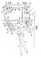
- the first embodiment is in the form of a pull-type round baler comprising a base frame 1 carrying a pair of ground- engaging wheels 2 and having attached thereto a drawbar 3 for connection to a tractor (not shown or other towing vehicle.
- a drive shaft 4 extends above the drawbar 3 and is connected at one end to an input shaft 5 of a gearbox 6, and connectable at the other end to a power-take-off shaft (also not shown) of the towing vehicle.
- Side walls 7 of the machine are attached to the base frame 1, the side walls partially defining a bale forming chamber by way of providing the sides therefor.
- the front and rear of the bale forming chamber are defined by portions of respective expandable members 8 and 9 which, when the machine is empty (Figure 1), form together with the side walls 7 a generally vertically oriented, wedge-shaped (as seen in side view) start chamber 11, and which expand on the formation of a bale to form a cylindrical bale chamber 11' ( Figure 2).
- the rear portion of the bale chamber is larger than the front portion and in fact forms a tailgate 12 for the machine which is pivotable disposed towards, but inset from, respective sides of the machine and are interconnected by a plurality of slats 22 which extend transversely of the machine, with each end of each slat extending past the associated chain and terminating just short of the side walls 7 as seen in Figure 5.
- slats 22 which extend transversely of the machine, with each end of each slat extending past the associated chain and terminating just short of the side walls 7 as seen in Figure 5.
- each chain 17 is mounted for rotation on an arm 23 which in turn is pivotally mounted on the frame via a pivot shaft 24 (common to both arms 23) offset from the centre of the arm and carried in a bush 25.
- each arm 23 comprises a pair of spaced members between which extend two spigots 26 on which the sprocket 19 and guide roller 21 are respectively mounted via bearings 27, only the sprocket being shown in Figure 4.
- the pivot shaft 24 has, at each end, a first portion of reduced diameter around which is disposed a torsion spring 28,-and a second portion of further reduced diameter which is received by the associated bush 25.
- Each spring 28 serves to bias the associated arm 23 in a clockwise direction as seen in Figures 1 and 2, whereby tension in the chain 17 is maintained and any slack resulting from wear is automatically taken up.
- the pivotal mounting of the arms 23 allows the orientation of the latter to change as a bale is being.formed as will be described.
- a conventional crop pick-up unit 14 which, in use, picks up crop material from the ground and delivers it to a combined crop feeder and bale support device 15 located at the mouth of the bale start chamber 11.
- a rotor 16 which extends across the full width of the bale chamber, i.e. extends between the side walls 7. The rotor 16 also serves to support a bale during its formation.
- the expandable member 8 partially defining the front surface of the chamber comprises two transversely spaced apart endless chains 17 each extending around, a driven sprocket 18, an idler sprocket, 19 and a non-toothed guide roller 21 disposed at respective apices of a triangle, as seen in side view in Figures 1 and 2.
- the chains 17 are locating one end 29 of each spring 28 against a stop 31 fixed to the related arm 23, and locating the other end 32 against a stop 33 fixed to one end of an arm 34 located on the outside of the associated side wall 7, the stop 33 extending through an arcuate slot 35 in the latter.
- Each arm 34 is pivotally mounted on the pivot shaft 24 via the associated bush 25 and has a reinforcing flange 36 ' extending around its periphery and away from the side wall 7.
- a bracket in the form of two spaced plates 37 is attached to the end of each arm 34 opposite to that of which the stop 33 is secured, a pivot pin 38 extending between the plates 37 and being attached to one end of a threaded rod 39, the other end of which is received by a flange 41 provided ⁇ on the related side wall 7.
- Nuts 42 adjustably secure each rod 39 to the related flange 41, whereby the arms 34 can be adjusted about the pivot shaft so as to move the stops 33, thereby to set the required torsion in the springs 28 and hence initial tension in the chains 17.
- the arms 23 and pivot shaft 24 are vertically adjustably mounted with respect to the related side wall 7 by virtue of the ends of the pivot shaft 24 and the bushes 25 being carried by respective plates 43 bolted by bolts 40 to the side wall 7 via slots 44 provided in the latter to permit relative sliding movement.
- Each plate 43 is formed with a flange 45 to which is attached one end of a threaded rod 46, the other end of which is adjustably attached to the related side wall flange 41 by nuts 47. Adjustment of the nuts 47 after loosening the bolts 40 either raises or lowers the plates' 43 relative . to the side walls 7 so as to move the pivot shaft 24, and hence the arms 23, to the desired position.
- the sprockets 19 move upwardly and away from the fixed upper sprockets 49 of the rear expandable member 9 by virtue of the arms 23 supporting the sprockets 19 pivoting in an anticlockwise direction as seen in Figures 1 and 2.
- This displacement has been kept to an acceptable minimum by providing the pivot shaft 24 substantially offset relative to the centre of the arms 23, and such that the sprockets 19 are positioned closer to the pivot shaft 24 than the guide rollers 21.
- the forward expandable member 8 is set so that, in the empty condition of the baler, the sprockets 19 are positioned slightly below the fixed sprockets 49 of the rear expandable member 9 and as close as possible to the forward, generally vertical run of the rear expandable member 9 without however the forward and rearward expandable members 8, 9 fouling each other during operation.
- the expandable member 9 also comprises a pair of spaced endless chains 48 located adjacent, but inset from, the respective side walls 7 and interconnected by a plurality of slats 22, the construction of which has yet to be described.
- the slats 22 extend beyond the chains 48 and terminate just short of the side walls 7 as shown in Figure-5.
- Each chain 48 extends around an upper fixed sprocket 49, a lower fixed sprocket 51 associated with the rotor 16, and one or both movable guide rollers 52 of each of an upper and lower pair thereof.
- the rollers 52 of each pair are rotatably mounted on respective ends of a crosspiece 53 of a generally T-shaped support, the stem 54 of which is provided with a pivot 55 intermediate its ends.
- Each pivot 55 extends from the stem 54 through an arcuate slot 56 in the associated side wall 7 and is attached to a support arm 57 pivotally mounted at 58 on said side wall at the centre of curvature of the slot 56.
- the two upper crosspieces 53 and the two lower crosspieces 53 are interconnected by respective transverse tubular beams 61 to ensure that the two upper and two lower supports pivot in unison.
- the springs 59 serve in the empty condition of the baler, to bias the upper T-shaped supports in a clockwise direction, and the lower supports in an anti-clockwise direction, as viewed in Figure 1, whereby one roller 52 of each pair engages the associated chain 48 to maintain tension therein and again take up any slack in the chain resulting from wear.
- the support arms 57 are pivoted in a direction towards the bale start chamber 11 until the pivot pins 55 engage the forward ends of the arcuate slots 56, under the action of the springs 59. It will also be noted th.at in this empty condition the rear expandable member 9 assumes a generally rectangular configuration with the run 7 facing the bale start chamber 11 being oriented generally vertically.
- the forward run 70 is moved in a rearward direction against the force of the springs 59 and inbetween the top and bottom sprockets 49 and 51, respectively.
- both guide rollers 52 of each pairs of guide rollers first engage the rear runs of the respective chains 48 and ultimately, the forward runs of the chains 48 engage the "opposite sides" of the guide rollers 52. Any "stretching" of the chains 48 resulting from wear is compensated by the T-shaped supports 53, 54 with the guide rollers 52 thereon moving generally radially outwardly, as seen with respect to the completed bale 13 in the bale chamber 11'.
- Such radially outward movement is made possible by the provision of the support arms 57 carrying the T-shaped supports being mounted for pivotal movement about the pivots 58, whereby the pivot pins 55 extending through the elongate slots 56 are moved away from the inner ends thereof.
- the rear expandable member 9 also cannot expand any further once both runs of the chains 48 engage the "opposite sides" of the guide rollers 52.
- the expandable member 9 also acts as the fixed bale forming means of a so-called soft core round baler.
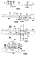
- slats 22 forming part of both the front and rear expandable members 8 and 9, and referring to Figures 6 to 8, these are formed from tubular stock and, as already mentioned, extend essentially the full width of the machines.
- the chains 17 and 48 are inset from the ends of the slats 22, as already described with reference to Figure 5, in order to reduce the unsupported length of each slat, whereby to lessen the chance of the slats flexing, and indeed being permanently deformed, when a bale is being formed. Also, the offset loading of the chains 17 and 48 is reduced substantially, resulting in an increased life of the chains or, alternatively, enabling lighter, and hence cheaper, chains to be used based on a required life.
- the use of tubular stock for the slats 22 maximises the inherent strength of the latter but gives rise to a problem in connecting the slats to the respective chains 17, 48.
- each slat 22 is basically flattened, but in a special, manner, at each end, the flattened portion 62 extending from the end of the slat to just beyond the point of connection to the chain 17 or 48.
- the flattened portion 62 of each end of each slat 22 comprises a flat rear portion 63 and an opposed front, working portion having a longitudinally-extending central portion 64 extending parallel to, but spaced from, the rear portion 63 and being flanked by two upstanding portions 65.
- the front surface of each flattened slat portion 62 is channel- shaped.
- each flattened portion 62 in the space between the rear portion 63 and the front central portion 64.
- Two longitudinally- spaced apertures 67 are provided through each flattened portion 62, including the insert 66, for the reception of bolts 68 by which the slat is attached to lugs 69 carried on either side of the associated chain 17, 48, the lugs being provided with holes to receive the bolts and together forming a surface complementary to the adjacent surface of the portion 63.
- the upstanding portions 65 of the flattened end portions 62 extend proud of the heads of the bolts 68, whereby the latter are protected from excessive abrasive wear by the crop material, and the likelihood of crop material.getting hooked around the bolt heads reduced. It will also be noted that the upstanding portion 65 lie generally within the outer periphery of the tubular slat as seen in end view.
- the threaded ends of the bolts 68 and the nuts 50 cooperating therewith are positioned to the side of the chains 17, 48 facing away from the bale to be formed and hence are also protected from abrasive wear by the crop material.
- the chains 17, 48 with the lugs 69 thereon are standard commercially available chains which means that the cost thereof is considerably lower than it would if special chains had to be employed.
- front and rear surfaces 60, 70 of the start chamber 11 are defined by the slats 22 on the runs of the chains 17 on the longest side of the triangle formed by the sprockets 18, 19 and the guide roller 21, and the slats 22 on the runs of the chains 48 between the upper and lower sprockets 49, 51, respectively.
- These surfaces 60, 70 change shape as a bale is formed, being transformed from linear to arcuate as has already been mentioned and as will be further described in more detail.
- each insert 73 comprises two hemispherical shells 74 formed with flanges 75 by which the insert is bolted to r the rotor 72, the sphere formed by the two shells containing a bush 76 of elastomeric synthetic plastics material.
- Each shell 74 is apertured to provide a through aperture 77 for a rod or finger 78 mounted in a radial extension 79 of a bush 81 of an elastomeric synthetic plastics material.
- Each rod 78 is retained in the extension 79 by a pin 82, and each bush 81 is rotatably mounted on a stationary crankshaft 83 the ends of which are received in bearings 84 provided in end plates 85 for the rotor 71.
- the rotor body is driven and rotates around the crankshaft 83, whereby the rods 78 are alternately extended (at the side of the rotor adjacent the pick-up unit 14) and retracted (at the side of the rotor adjacent the other rotor 16) by way of sliding in and out of the apertures 77 and bushes 76, the ends of the rods describing the circle indicated at 80.
- the combined crop feeder and bale support device 15, together with the facing runs 60, 70 of the expandable members 8, 9 when in the empty condition of the baler define the generally triangular and upright bale starting chambers 1 with the device 15 being provided at a distance beneath the lower end of the member 8, thus providing therebetween a bale chamber inlet opening.
- the device 15 is further mounted proximate, and forwardly of the rotor 16 so that, in the empty condition of the baler, the generally vertical run 70 of the rear bale forming member 9 is offset to the rear of the device 15, which in part forms the base of the triangular bale starting chamber 11.
- the device 15 is further also positioned relative to thelower sprockets 18 of the front bale forming member 8 and the rotor 16 (which is part of the rear bale forming member 9) so that, as a bale is nearing completion within the bale chamber, the bale is supported at least in part by the cylindrical body 71 of the device 15.
- the cylindrical body 71 is positioned, together with other components on a circumference defining the cylindrical bale chamber 11' when at its maximum diameter.
- the device 15 is also positioned relative to the bale chamber 11' so that, as a bale is being formed in the bale chamber and is nearing completion, its centre of gravity is moved from generally above the device 15 to the side thereof opposite to the side facing the pick-up device 14.
- the retractable fingers 78 are substantially in the retracted position at the point on the cylindrical body 71 of the device 15 where, when a bale is being completed in the bale chamber 11', the bale is supported on the cylindrical body, thereby avoiding the fingers penetrating into the bale and adversely affecting the surface thereof.
- the fingers 78 are extended to the maximum at the side of the cylindrical body 71, facing the discharge end of the pick-up device 14 in order. to take over crop material therefrom and are retracted gradually from the maximum extension position to said part of contact of the bale on the cylindrical body 71, as the device is rotated.
- the rotor 16 will now be described.
- the function of the rotor 16 is to provide a positive support for a bale during formation, which support does not impart any substantial vibration to the bale which might impair the formation thereof and/or cause unacceptable wear and/or damage to the machine.
- the chains 48 extend around sprockets 51 associated with the rotor 16 and if the rotor were not provided, the slats 22 would continuously pass beneath the bale being formed, thereby raising the bale on each occasion and thus subjecting the bale to vibration in the generally vertical plane.
- the rotor 16 overcomes this problem by providing pockets for the slats 22 to enter as they pass beneath the bale, whereby the rotor, together with the slats received in the pockets thereof, provide a substantially smooth or continuous surface on which the bale is supported.
- the rotor 16 comprises a hollow tubular core 86 extending between the two sprockets 51 and closed at each end by a plate 87 formed with a tubular extension 88 of reduced diameter and concentric with the core and formed with an annular recess 89 around its outer end.
- the recess 89 receives one end of a tube 91 having the same outer diameter as the extension 88 and being closed at its other and outer end by an end plate 92 which is bolted to a flange 93 carried by a stub shaft 94 by which the rotor is mounted for rotation in bearings (not shown) provided in the respective side walls 7.
- Each tube 91 is surrounded along the majority of its length by a further tube of the same outer diameter as the core 86 and representing an extension 86' of that core.
- Each core extension 86' is supported by two annular discs 95 carried by the tube 91.
- respective outer rotor surfaces 96 and 96' which are generally star-shaped in cross-section as seen in Figure 11, thus providing four longitudinally extending pockets 97 for the reception of the slats 22 associated with the chains 48.
- the surfaces 96, 96' are each formed from four identical sections of sheet metal welded together at the "points" of the star and to the respective end plates 87, 95 of the rotor 16.
- the two sprockets 51 associated with the rotor 16 are annular and each is welded to an annular disc 99 attached to the tube 91.
- the two ends of the rotor 16 are mounted on the main rotor body by sliding the tubes 91 into the recesses 89 in the extension 88 and bolting the sprockets 51 to respective discs 98 secured to the extensions 88 via bolts 90 welded to the sprockets 51.
- the sprockets 51 are inset from the ends of the rotor to match the insetting of the chains 48 from the ends of the slats 22.
- a sprocket 102 on the output shaft 103 of the gearbox 6 drives, via a chain 100, one sprocket of a triple sprocket 104 on a shaft 105 on which the sprocket 18 of the front expandable member 8 is mounted, whereby the chains 17 are driven in a clockwise direction as seen in Figures 1 and 2. Both chains 17 are driven since the shaft 105 is common to both sprockets 18.
- a further chain 106 extends around a second sprocket of the triple sprocket 104 and around a sprocket 107 on a common shaft 108 for the two sprockets 49 of the rear expandable member 9, whereby the two chains 48 are also driven in a clockwise direction as seen in- Figures 1 and 2.
- the runs of the chains 17 and 48 partially defining the start chamber 11 move in opposite directions so as to impart a rolling motion to the crop material fed to the start chamber.
- a chain 109 extends around the third sprocket of the triple sprocket 104 and around a sprocket 111 provided on one end of the cylindrical body 71 of the rotor 15, whereby the latter is driven in a clockwise direction as seen in Figures 1 and 2.
- a pulley 112 is also coupled to the sprocket 111 and a belt 113 extends from that pulley to a pulley 114 on the pick-up unit 14 so as to drive the latter also in a clockwise direction as seen in Figures 1 and 2.
- the machine is hitched to the tractor or other towing vehicle via the drawbar 3, and the driveshaft 4 connected to the tractor PTO, whereby the chains 17, 48, the rotor 15 and the pick-up 14 are driven as described above.
- the machine is towed across a field to previously cut crop material, the latter is picked up by the pick-up 14 and conveyed overcrop and rearwardly towards the rotor 15.
- the extended fingers or rods 78 of the latter take over the crop material and feed it into the mouth of the start chamber 11 against the rising run of the chains 48 and associated slats 22, the fingers then retracting and thus releasing the crop material.
- the slats 22 are relatively closely spaced, and they serve to carry the crop material a certain way into the start chamber 11 before the crop tumbles under gravity and falls downwardly, assisted by the generally downwardly moving slats 22 of the front expandable member 8.
- the relatively gentle tumbling action of the crop material results in a generally soft core for the bale being formed.
- the rolling action imparted to the crop material by the rotor 15, and the slats 22 on the facing runs of the chains 17 and 48 results in a smaller core than would otherwise pertain in a conventional soft core baler.
- thelcore usually starts to roll at a distance above the combined feeder and support device 15 and inbetween the facing runs 60, 70 of the bale forming members 8, 9.
- the start chamber 11 becomes full, whereupon the core presses increasingly harder on the slats 22 of the facing runs of the chains 17 and 48 with the result that runs of chains 17 are urged to the left as seen in Figure 1, and the runs of the chains 48 are urged to the right, the former against the action of the springs 28 and the latter against the action of the springs 59.
- the layers of crop material surrounding the soft core begin to be more consolidated, the density of the bale in fact increasing to the outer shell thereof since the springs 28 and 59 progressively increase the tension in the chains 17 and 48.
- the degree of compaction depends on the forces exerted by the springs 28 and 59. With the illustrated arrangement it is easy and convenient to vary these spring forces and thus vary the density of the bale. Therefore, if it is desired to produce soft- core bales pretty much as are conventionally produced with soft core balers, it is sufficient to adjust the springs 28 and 59 accordingly.
- this outer shell depends on the amount of crop material fed into the bale chamber after the bale has reached-its maximum diameter. This is comparable to the hard shell which can be produced with soft core balers and is totally independartof the initial setting of the springs 28, 59.
- the bale As the bale is nearing completion in the bale chamber 11', it is supported in part on the cylindrical body 71 of the device 15 and on the rotor 16, together with the r slats 22 of the rear bale forming member 9 as they pass in the successive pockets 79 of the rotor. This occurs without any undue vibration of the bale in the bale chamber, and hence also of the baler. It will also be appreciated, mainly from Figure 2, that the forward bale forming member 8, together with the sprockets 18, and the rearward bale forming member 9, together with the lower pairs of guide rollers 52 on the T-shaped support members 53, 54, assist in supporting the weight of the bale in the bale chamber.
- the particular mounting of the T-shaped support members 53, 54 provides compensation for any "stretching" of the bale forming member 9 as a result of wear.
- the tailgate 12 is raised (by means not shown) above the axis 108 of the sprockets 49 and since the centre of gravity of the bale 15 lies within the rear portion of the bale chamber 11', there is a natural tendency for it to roll from the machine on the raising of the tailgate. This tendency is augmented by the action of the rotor 15, which continues to be driven, and thus positive discharge of a completed bale is achieved.
- the springs 28 and 59 return the arms 23 and supports 53, 54, respectively, to the positions of Figure 1, whereby the tapered start chamber 11 is re-formed ready for forming the next bale.
- the machine is capable of forming bales of less than the maximum diameter as bale discharge can be effected at any time by raising the tailgate 12. Whilst any bale less than the maximum size will not have the heavily compacted outer layer or shell, the latter nevertheless will be such that the bale will hold together especially when the springs 28, 59 have been set to give an increased density to the bale being formed.
- FIG 13 shows a modified arrangement of the guide means for guiding the chains 48 when a bale has reached its maximum diameter in the bale chamber 11'.
- Figure 13 shows one T-shaped support 53, 54 in the position adopted when a completed bale has been formed.
- each support 53, 54 is provided with two sprockets 115, one in engagement with the front run of the associated chain at a location proximate one guide roller 52 and the other in engagement with the rear run, again at a location proximate to the other guide roller 52.
- the chains 48 engage both "sides" of the rollers 52 when in the position (bale complete) of Figure 13.
- This arrangement improves the guidance of both runs of the chains 48 on the guide rollers 52 when a bale has reached its maximum size within the bale chamber 11' by positively holding the chains 48 in alignment with the rollers 52.
- FIGs 14 and 15 shown an alternative embodiment of round baler which, in the main, is similar to that of Figures 1 to 12, the differences being in respect of the chain tensioning devices associated with the front and rear expandable members 8 and 9.
- the arms 23 are replaced by arms 116 which carry at one end the guide rollers 21, with the sprockets 18 and 19 being fixed.
- Each arm 116 is pivoted intermediate its ends on a pivot 117, with the other end of the arm connected to one end of a tension spring 118 attached at its other end to the machine frame.
- the gaps between the sprockets 19 of the front expandable member 8 and the sprockets 49 of the rear expandable member 9 remain constant and small so the likelihood of any loss of crop material therethrough is small.
- the sprockets 19 are movable relative to the sprockets 49 as a bale being formed increases in size so that care has to be taken with the disposition and mounting of the sprockets 19 with the crop loss problem in mind, as already explained.
- tension in the chains 48 is maintained only by the upper member and not the upper and lower members (supports 53, 54) as in the first embodiment.
- the lower supports 53, 54 are replaced by arms 119 which carry the guide rollers 52, with the lower arms being mounted for limited movement relative to the side walls 7 by virtue of a pair of elongated slots 121 formed in the side walls which slidably receive mounting pins 112 attached to the associated arms 119.
- This particular mounting like the provision of the pivot arms 57 in the embodiment of Figures I to 12, provides compensation for any "stretching" of the chains" 48 as a result of wear.
- the upper supports 53, 54 are replaced by arms 123 which carry the rollers 52 and are each centrally pivoted on one end of a further arm 124 which is pivoted at its other end to the machine frame.
- One end of a cable 125 is attached to each arm 124 intermediate its ends, the other end of the cable being secured to one end of a tension spring 126 which in turn has its other end attached to the machine frame, the cable passing over a pulley 127 on an extension 128 on the frame.
- the present invention provides a round baler which can produce bales with a hard outer shell whilst the density of the crop material within the outer r shell can he varied greatly at will from a low density comparable to the characteristics of bales produced with conventional soft core bales to a high density as is known from balers having an expandable bale chamber, thus providing greater flexibility to the operator and combining advantages of conventional soft and hard core balers.
- the slats 22 are of a strength sufficient to exert the required force on the bale as it is being formed and yet are not bulky. Furthermore standard chains can be used.
- the insetting of the points of connection to the chains from the ends of the slats helps to reduce chain wear as it has been found that chains located at the extreme ends of the slats are subjected to uneven loading and hence relatively fast wear. This insetting also reduces the unsupported length of the slats so that less robust tubing can be used therefor than would otherwise be the case.
- slats of 1.2 metres are employed, with flattened portions of 30cms, and internal and external diameters of 38mm and 42mm.
- the chains 17 and 48 are inset from the ends of the slats by 21 cms.
- the rotor 15 has a dual function in feeding crop material to the bale chamber from the pick-up unit 14,and in helping to support the bale as it is being completed.
- the rotor 15 thus performs an important part in the formation of a bale and without its presence, the pick-up unit 14 would have to be mounted much closer to the mouth of the bale chamber to an extent that it would inevitably have to support each bale being formed, and conventional pick-up units are not constructed to fulfil this purpose.
- the function of the rotor 16 is also important in lending further support to each bale as it is formed and in so doing to present,in conjunction with the slats 22 a substantially smooth surface to the bale.
- the pockets 97 are formed in the surface of the rotor 16 to accommodate the slats 22 as they pass therearound. As already explained, this prevents the slats from imparting generally vertical vibrations to the bale being formed which would impair formation.
- the member defining the smaller portion of the bale chamber 11' (be it the front or rear member) may be replaced by one or more of a fixed type of bale-forming means employing, for example, fixed rollers, or fixed chain or belt conveyors.
- the bale-forming members 8 and 9 may be augmented by one or more fixed bale-forming means.
- the chain type bale forming means 8, 9 may be replaced by belt type bale forming members.
- the present invention provides a round baler capable of producing a bale with a hard outer shell (soft core bale characteristics), and with either a relatively high density (hard core bale characteristic), or a rather low density of crop material within the outer shell, without giving rise to an over complicated structure.
- the machine can produce a maximum sized bale (1.2 metres in diameter) in approximately two minutes, provided crop material is fed to the bale chamber at the appropriate rate.
- this bale-forming time between 1/3 and 1/4 is devoted to forming the hard shell, i.e. this is the period in which the runs of the chains 17 and 48 are positively supported by the "opposed sides" of all the sprockets and guide rollers provided within the envelopes formed by the respective chains.
- baler of the type having an expanding bale chamber, bale with an extra hard outer shell, such as is obtained with known balers of the type having a fixed chamber and commonly referred to as soft core balers.
- the tension initially set in the chains 17 and 48 determines the hardness of the core as well as influencing the overall density of the bale except for the hardness of the outer shell which basically is determined by the amount of crop material fed into the bale chamber after the latter has expanded to its maximum diameter.
- a baler in accordance with the present invention provides a core which is smaller than that provided by known soft core machines due. to the positive rolling action imparted to the core by the hale-forming members.
- the baler produces a highly satisfactory bale having qualities of both soft core and hard core bales without, as already mentioned, being of complicated mechanical construction.
Abstract
Description
- This invention relates to agricultural balers and more particularly to so-called round balers which produce cylindrical bales or rolls of cross material.
- In general, round balers are of two types: the expanding chamber type which produces balers with a relatively hard core and a generally high and relatively constant density throughout; and the fixed chamber type which produces bales with a relatively soft core but a relatively compacted or hard outer layer or shell.
- The advantages of hard core balers are that they pack more crop material into a bale compared with a similarly sized soft core bale, and they can produce bales of any size up to the maximum which a given machine is capable of producing, with all sizes of bales being in generally good order from the standpoint of being subjected to handling without falling apart. The advantages of soft core balers are that they produce bales with a reduced tendency to moulding if the crop material is baled wet; the bale core presents no problems to cattle when feeding from the bale (whereas hard cores can be difficult to tear apart); they produce bales with good weathering characteristics due to the hard shell, and the latter ensures a good looking,"clean" bale which is very stable when being handled; the balers are of relatively simple design; and the balers normally have no difficulty in forming a bale core which can sometimes be a problem with hard core balers when handling short lengths of crop material.
- It is an object of the present invention to provide a round baler which affords some of the advantages of both a hard core balers when handling short lengths of crop material.
- It is an object of the present invention to provide a round baler which affords some of the advantages of both a hard core baler and a soft core baler. To this end, it is preferable to provide a generally vertical start chamber in which to commence the formation of a bale and there are two problems with this requirement,the first being that of achieving a satisfactory in-feed of crop material to the start chamber, and the second being that of providing adequate support for the bale during formation.
- According to one aspect of the present invention there is provided a round baler having a bale-forming chamber, pick-up means operable to pick-up crop from the ground for feeding to the bale-forming chamber,and crop feeder means operable to receive the crop from the pick-up means and to transfer it to the bale-forming chamber,the crop feeder means being disposed so as to assist in supporting the bale during formation thereof.
- According to another aspect of the present invention there is provided a round baler, having a bale-forming chamber defined at least in part by at least one expandable bale-forming means arranged so as to define initially a generally wedge-shaped start chamber for the bale,the start chamber being generally vertically oriented and having a crop inlet at the base thereof, pick-up means operable to pick-up crop from the ground for feeding to the crop inlet of the bale-forming chamber, and crop feeder means operable to receive crop from the pick-up means and to transfer it to the bale-forming chamber, the crop feeder means being disposed so as to assist in supporting the bale as it is formed.
- Round balers in accordance with the present invention will now be described in greater detail, by way of example, with reference to the accompanying drawings, in which:-
- Figure 1 is a schematic side view of a first embodiment of round baler showing the machine empty,
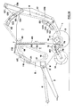
- Figure 2 is a view similar to that of Figure 1 but showing the machine with a completed bale,
- Figure 3 is an enlarged view of a portion of Figure 1,
- Figure is a side view of Figure 3,
- Figure 5 is a schematic view of a-component of Figure 1,
- Figure 6 is a partial sectional view, on the line VI-VI of Figure 5,
- Figure 7 is plan view of Figure 6,
- Figure 8 is a sectional view on the line VIII-VIII of Figure 7,
- Figure 9 is an enlarged view of a still further component of Figure 1,
- Figure 10 is a partial sectional view on the line X-X of Figure 9,
- Figure 11 is an enlarged view of yet another position of Figure 1,
- Figure 12 is a partial longitudinal section of the component of Figure 11,
- Figure 13 is a view of an alternative component for the first embodiment, and
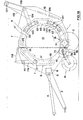
- Figures 14 and 15 are views similar to those of Figures 1 and 2, respectively, but showing a second embodiment.
- Referring first to Figures 1 and 2, the first embodiment is in the form of a pull-type round baler comprising a
base frame 1 carrying a pair of ground-engaging wheels 2 and having attached thereto adrawbar 3 for connection to a tractor (not shown or other towing vehicle. Adrive shaft 4 extends above thedrawbar 3 and is connected at one end to aninput shaft 5 of agearbox 6, and connectable at the other end to a power-take-off shaft (also not shown) of the towing vehicle.Side walls 7 of the machine are attached to thebase frame 1, the side walls partially defining a bale forming chamber by way of providing the sides therefor. The front and rear of the bale forming chamber are defined by portions of respectiveexpandable members start chamber 11, and which expand on the formation of a bale to form a cylindrical bale chamber 11' (Figure 2). Eachside wall 7 is split, with theexpandable member 8 forming a front portion of the bale chamber in conjunction with one portion each side wall, and theexpandable member 9 forming a rear portion of the bale chamber in conjunction with the =other portion of each side wall. - As seen in Figures 1 and 2, the rear portion of the bale chamber is larger than the front portion and in fact forms a
tailgate 12 for the machine which is pivotable disposed towards, but inset from, respective sides of the machine and are interconnected by a plurality ofslats 22 which extend transversely of the machine, with each end of each slat extending past the associated chain and terminating just short of theside walls 7 as seen in Figure 5. The construction of eachslat 22 will be described hereinafter. - With specific reference to Figures 3 and 4, the
sprocket 19 andguide roller 21 associated with eachchain 17 are mounted for rotation on anarm 23 which in turn is pivotally mounted on the frame via a pivot shaft 24 (common to both arms 23) offset from the centre of the arm and carried in abush 25. It will be seen from Figure 4 that eacharm 23 comprises a pair of spaced members between which extend twospigots 26 on which thesprocket 19 andguide roller 21 are respectively mounted viabearings 27, only the sprocket being shown in Figure 4. Thepivot shaft 24 has, at each end, a first portion of reduced diameter around which is disposed atorsion spring 28,-and a second portion of further reduced diameter which is received by the associatedbush 25. Eachspring 28 serves to bias the associatedarm 23 in a clockwise direction as seen in Figures 1 and 2, whereby tension in thechain 17 is maintained and any slack resulting from wear is automatically taken up. The pivotal mounting of thearms 23 allows the orientation of the latter to change as a bale is being.formed as will be described. - This tensioning of each
chain 17 is achieved by upwardly in order to effect discharge of a completed bale 13 (Figure 2) from the machine. With this differential sizing of the two portions of the bale chamber, the centre of gravity of a completed bale lies within the rear portion of the bale chamber, whereby there is a natural tendency for a completed bale to roll from the machine once thetailgate 12 has been raised,_which tendency greatly facilitates bale discharge. - Pivotally mounted at the front of the machine is a conventional crop pick-
up unit 14 which, in use, picks up crop material from the ground and delivers it to a combined crop feeder andbale support device 15 located at the mouth of thebale start chamber 11. Located within the rear portion of the bale chamber and disposed at the front bottom corner adjacent the feeder andsupport device 15 is arotor 16 which extends across the full width of the bale chamber, i.e. extends between theside walls 7. Therotor 16 also serves to support a bale during its formation. - Having described the overall machine in general, certain components will now be described in greater detail with reference to Figures 3 to 12, in addition to Figures 1 and 2, of the drawings. Looking first at the bale chamber, the
expandable member 8 partially defining the front surface of the chamber comprises two transversely spaced apartendless chains 17 each extending around, a drivensprocket 18, an idler sprocket, 19 and anon-toothed guide roller 21 disposed at respective apices of a triangle, as seen in side view in Figures 1 and 2. Thechains 17 are locating oneend 29 of eachspring 28 against astop 31 fixed to therelated arm 23, and locating theother end 32 against astop 33 fixed to one end of anarm 34 located on the outside of the associatedside wall 7, thestop 33 extending through anarcuate slot 35 in the latter. Eacharm 34 is pivotally mounted on thepivot shaft 24 via the associatedbush 25 and has a reinforcing flange 36 ' extending around its periphery and away from theside wall 7. A bracket in the form of two spacedplates 37 is attached to the end of eacharm 34 opposite to that of which thestop 33 is secured, apivot pin 38 extending between theplates 37 and being attached to one end of a threadedrod 39, the other end of which is received by aflange 41 provided \ on therelated side wall 7.Nuts 42 adjustably secure eachrod 39 to therelated flange 41, whereby thearms 34 can be adjusted about the pivot shaft so as to move thestops 33, thereby to set the required torsion in thesprings 28 and hence initial tension in thechains 17. - The
arms 23 andpivot shaft 24 are vertically adjustably mounted with respect to therelated side wall 7 by virtue of the ends of thepivot shaft 24 and thebushes 25 being carried byrespective plates 43 bolted bybolts 40 to theside wall 7 viaslots 44 provided in the latter to permit relative sliding movement. Eachplate 43 is formed with aflange 45 to which is attached one end of a threadedrod 46, the other end of which is adjustably attached to the relatedside wall flange 41 bynuts 47. Adjustment of thenuts 47 after loosening thebolts 40 either raises or lowers the plates' 43 relative . to theside walls 7 so as to move thepivot shaft 24, and hence thearms 23, to the desired position. - After adjustment, the
pivot shaft 24 and thearms 23 coupled thereto are firmly held in the selected vertical position, on the one hand, by thenuts 47 and the threadedrod 46, and on the other hand, by thebolts 40 firmly tightened to theside walls 7 through theelongate slots 44 therein. It will be noted that by this adjustment, the vertical position of thesprockets 19 relative to fixedupper sprockets 49 of the rearexpandable member 9. When the baler is in its empty condition, can be changed. It will also be noted that, as a bale is being formed in the bale chamber, thesprockets 19 move upwardly and away from the fixedupper sprockets 49 of the rearexpandable member 9 by virtue of thearms 23 supporting thesprockets 19 pivoting in an anticlockwise direction as seen in Figures 1 and 2. This displacement, however, has been kept to an acceptable minimum by providing thepivot shaft 24 substantially offset relative to the centre of thearms 23, and such that thesprockets 19 are positioned closer to thepivot shaft 24 than theguide rollers 21. Using the adjustability of thepivot shaft 24 in a generally vertical directions provided by theadjustable plates 43, the forwardexpandable member 8 is set so that, in the empty condition of the baler, thesprockets 19 are positioned slightly below the fixedsprockets 49 of the rearexpandable member 9 and as close as possible to the forward, generally vertical run of the rearexpandable member 9 without however the forward and rearwardexpandable members - It will also be noted that, as a bale is being formed in the bale chamber, the
arms 23 pivot. anticlockwise, as seen in Figures 1 and 2, until theguide rollers 21 engage the opposed runs of theendless chains 17 forming part of theexpandable member 8. At this moment, further pivoting of thearms 23 in the anticlockwise directions, and hence further "expansion" of the.expandable member 8, becomes impossible, whereby the inner run of theexpandable member 8 assumes a virtually fixed position which is very much the same as the fixed position assumed by the bale forming members in a so-called soft core baler or a baler with a fixed bale chamber. - Turning now to the
expandable member 9, this also comprises a pair of spacedendless chains 48 located adjacent, but inset from, therespective side walls 7 and interconnected by a plurality ofslats 22, the construction of which has yet to be described. Again, theslats 22 extend beyond thechains 48 and terminate just short of theside walls 7 as shown in Figure-5. Eachchain 48 extends around an upper fixedsprocket 49, a lowerfixed sprocket 51 associated with therotor 16, and one or bothmovable guide rollers 52 of each of an upper and lower pair thereof. When the machine is empty (Figure 1), only oneroller 52 of each pair is in engagement with thechains 48, but when a bale'nears completion, both rollers of each pair are in engagement with thechains 48. Also, under this condition as a bale nears completion in the bale r chamber 11', both the inner and outer runs (as seen with respect to the bale chamber) of thechains 48 engage therollers 52. Therollers 52 of each pair are rotatably mounted on respective ends of acrosspiece 53 of a generally T-shaped support, thestem 54 of which is provided with apivot 55 intermediate its ends. Eachpivot 55 extends from thestem 54 through anarcuate slot 56 in the associatedside wall 7 and is attached to asupport arm 57 pivotally mounted at 58 on said side wall at the centre of curvature of theslot 56. The end of each stem 54 of the T-shaped support remote from thecrosspiece 53 is connected to one=end of atension spring 59, the other end of which is attached to the associatedside wall 7. The twoupper crosspieces 53 and the twolower crosspieces 53 are interconnected by respective transversetubular beams 61 to ensure that the two upper and two lower supports pivot in unison. Thesprings 59 serve in the empty condition of the baler, to bias the upper T-shaped supports in a clockwise direction, and the lower supports in an anti-clockwise direction, as viewed in Figure 1, whereby oneroller 52 of each pair engages the associatedchain 48 to maintain tension therein and again take up any slack in the chain resulting from wear. Also, thesupport arms 57 are pivoted in a direction towards the bale startchamber 11 until the pivot pins 55 engage the forward ends of thearcuate slots 56, under the action of thesprings 59. It will also be noted th.at in this empty condition the rearexpandable member 9 assumes a generally rectangular configuration with therun 7 facing the bale startchamber 11 being oriented generally vertically. - As a bale is being formed in the bale chamber 11', the
forward run 70 is moved in a rearward direction against the force of thesprings 59 and inbetween the top andbottom sprockets rollers 52 of each pairs of guide rollers first engage the rear runs of therespective chains 48 and ultimately, the forward runs of thechains 48 engage the "opposite sides" of theguide rollers 52. Any "stretching" of thechains 48 resulting from wear is compensated by the T-shapedsupports guide rollers 52 thereon moving generally radially outwardly, as seen with respect to the completedbale 13 in the bale chamber 11'. Such radially outward movement is made possible by the provision of thesupport arms 57 carrying the T-shaped supports being mounted for pivotal movement about thepivots 58, whereby the pivot pins 55 extending through theelongate slots 56 are moved away from the inner ends thereof. - It will be appreciated that, like the forward
expandable member 8, the rearexpandable member 9 also cannot expand any further once both runs of thechains 48 engage the "opposite sides" of theguide rollers 52. Thus, again in this condition, theexpandable member 9 also acts as the fixed bale forming means of a so-called soft core round baler. - It will also be appreciated that as a result of the
guide rollers chains guide rollers - Returning now to the
slats 22 forming part of both the front and rearexpandable members chains slats 22, as already described with reference to Figure 5, in order to reduce the unsupported length of each slat, whereby to lessen the chance of the slats flexing, and indeed being permanently deformed, when a bale is being formed. Also, the offset loading of thechains slats 22 maximises the inherent strength of the latter but gives rise to a problem in connecting the slats to therespective chains - To overcome this problem, each
slat 22 is basically flattened, but in a special, manner, at each end, the flattenedportion 62 extending from the end of the slat to just beyond the point of connection to thechain portion 62 of each end of eachslat 22 comprises a flatrear portion 63 and an opposed front, working portion having a longitudinally-extendingcentral portion 64 extending parallel to, but spaced from, therear portion 63 and being flanked by twoupstanding portions 65. Thus the front surface of each flattenedslat portion 62 is channel- shaped. - The flattening of the ends of the
slats 22 destroys the inherent strength of the previous tubular configuration and in order to restore this strength, a fillet or insert 66 cut from flat metal strip is disposed inside each flattenedportion 62 in the space between therear portion 63 and the frontcentral portion 64. Two longitudinally- spacedapertures 67 are provided through each flattenedportion 62, including theinsert 66, for the reception ofbolts 68 by which the slat is attached to lugs 69 carried on either side of the associatedchain portion 63. It will be noted from Figure 8 that theupstanding portions 65 of the flattenedend portions 62 extend proud of the heads of thebolts 68, whereby the latter are protected from excessive abrasive wear by the crop material, and the likelihood of crop material.getting hooked around the bolt heads reduced. It will also be noted that theupstanding portion 65 lie generally within the outer periphery of the tubular slat as seen in end view. - The threaded ends of the
bolts 68 and the nuts 50 cooperating therewith are positioned to the side of thechains chains lugs 69 thereon are standard commercially available chains which means that the cost thereof is considerably lower than it would if special chains had to be employed. - It will be appreciated that the front and
rear surfaces start chamber 11 are defined by theslats 22 on the runs of thechains 17 on the longest side of the triangle formed by thesprockets guide roller 21, and theslats 22 on the runs of thechains 48 between the upper andlower sprockets surfaces - Turning now to the combined crop feeder and
bale support device 15, and referring to Figures 9 and 10, this comprises ahollow rotor 71 having a smooth outer surface and provided with two diametrically opposed rows ofapertures 72 each of which receives aninsert 73 from within the rotor, the insert being bolted to the rotor. Eachinsert 73 comprises twohemispherical shells 74 formed withflanges 75 by which the insert is bolted to r therotor 72, the sphere formed by the two shells containing abush 76 of elastomeric synthetic plastics material. Eachshell 74 is apertured to provide a throughaperture 77 for a rod orfinger 78 mounted in aradial extension 79 of abush 81 of an elastomeric synthetic plastics material. Eachrod 78 is retained in theextension 79 by apin 82, and eachbush 81 is rotatably mounted on astationary crankshaft 83 the ends of which are received inbearings 84 provided inend plates 85 for therotor 71. The rotor body is driven and rotates around thecrankshaft 83, whereby therods 78 are alternately extended (at the side of the rotor adjacent the pick-up unit 14) and retracted (at the side of the rotor adjacent the other rotor 16) by way of sliding in and out of theapertures 77 andbushes 76, the ends of the rods describing the circle indicated at 80. - The combined crop feeder and
bale support device 15, together with the facing runs 60, 70 of theexpandable members bale starting chambers 1 with thedevice 15 being provided at a distance beneath the lower end of themember 8, thus providing therebetween a bale chamber inlet opening. Thedevice 15 is further mounted proximate, and forwardly of therotor 16 so that, in the empty condition of the baler, the generallyvertical run 70 of the rearbale forming member 9 is offset to the rear of thedevice 15, which in part forms the base of the triangularbale starting chamber 11. - The
device 15 is further also positioned relative tothelower sprockets 18 of the frontbale forming member 8 and the rotor 16 (which is part of the rear bale forming member 9) so that, as a bale is nearing completion within the bale chamber, the bale is supported at least in part by thecylindrical body 71 of thedevice 15. Hence thecylindrical body 71 is positioned, together with other components on a circumference defining the cylindrical bale chamber 11' when at its maximum diameter. - However, the
device 15 is also positioned relative to the bale chamber 11' so that, as a bale is being formed in the bale chamber and is nearing completion, its centre of gravity is moved from generally above thedevice 15 to the side thereof opposite to the side facing the pick-updevice 14. - The
retractable fingers 78 are substantially in the retracted position at the point on thecylindrical body 71 of thedevice 15 where, when a bale is being completed in the bale chamber 11', the bale is supported on the cylindrical body, thereby avoiding the fingers penetrating into the bale and adversely affecting the surface thereof. Thefingers 78 are extended to the maximum at the side of thecylindrical body 71, facing the discharge end of the pick-updevice 14 in order. to take over crop material therefrom and are retracted gradually from the maximum extension position to said part of contact of the bale on thecylindrical body 71, as the device is rotated. - Referring to Figures 11 and 12, the
rotor 16 will now be described. The function of therotor 16 is to provide a positive support for a bale during formation, which support does not impart any substantial vibration to the bale which might impair the formation thereof and/or cause unacceptable wear and/or damage to the machine. As already described, thechains 48 extend aroundsprockets 51 associated with therotor 16 and if the rotor were not provided, theslats 22 would continuously pass beneath the bale being formed, thereby raising the bale on each occasion and thus subjecting the bale to vibration in the generally vertical plane. Therotor 16 overcomes this problem by providing pockets for theslats 22 to enter as they pass beneath the bale, whereby the rotor, together with the slats received in the pockets thereof, provide a substantially smooth or continuous surface on which the bale is supported. - The
rotor 16 comprises ahollow tubular core 86 extending between the twosprockets 51 and closed at each end by aplate 87 formed with atubular extension 88 of reduced diameter and concentric with the core and formed with anannular recess 89 around its outer end. Therecess 89 receives one end of atube 91 having the same outer diameter as theextension 88 and being closed at its other and outer end by anend plate 92 which is bolted to aflange 93 carried by astub shaft 94 by which the rotor is mounted for rotation in bearings (not shown) provided in therespective side walls 7. Eachtube 91 is surrounded along the majority of its length by a further tube of the same outer diameter as thecore 86 and representing an extension 86' of that core. Each core extension 86' is supported by twoannular discs 95 carried by thetube 91. - On the
main core 86 and the two core extensions 86' of therotor 16 there are mounted respective outer rotor surfaces 96 and 96', which are generally star-shaped in cross-section as seen in Figure 11, thus providing four longitudinally extendingpockets 97 for the reception of theslats 22 associated with thechains 48. Thesurfaces 96, 96' are each formed from four identical sections of sheet metal welded together at the "points" of the star and to therespective end plates rotor 16. - The two
sprockets 51 associated with therotor 16 are annular and each is welded to anannular disc 99 attached to thetube 91. On assembly, the two ends of therotor 16 are mounted on the main rotor body by sliding thetubes 91 into therecesses 89 in theextension 88 and bolting thesprockets 51 torespective discs 98 secured to theextensions 88 viabolts 90 welded to thesprockets 51. Thus thesprockets 51 are inset from the ends of the rotor to match the insetting of thechains 48 from the ends of theslats 22. - As the
rotor 16 rotates', theslats 22 move into thepockets 97 as thechains 48 pass around thesprockets 51, whereby a substantially continuous support surface is seen, by thebale 13 being formed as presented at any given instant by a slat and a "point" of the star-shaped rotor. In this respect, it will be seen from Figure 11 that when aslat 22 is received in apocket 97, the radially outer portion of the main body of the slat is located at thecircle 101 circumscribed by the "points" of therotor 16. - From the drawings, and more especially from Figure 2, it will be appreciated that only part of the weight of a bale being formed on the bale chamber is supported on the rotor 16 (and on a
slat 22 received in apocket 97 thereof and on the chains 49), another part of the bale weight being supported, as already mentioned, by the combined feeder andbale supporting device 15. - It should be noted that the number of teeth on each
sprocket 51 is N times the number of links in thechains 48 betweenadjacent slats 22, where N is an integer, although preferably not one. Also, the number of teeth on eachsprocket 51 is a multiple of the number of pockets provided in the rotor. It will be seen from Figure 11 that in the first embodiment, each sprocket has sixteen teeth which is a multiple of the fourpockets 97 and which makes N=4 since aslat 22 is attached to every fourth link of thechains 48. - The drives for the various driven components of the baler are shown in Figure 2 of the drawings, these being omitted from Figure 1 for clarity. A
sprocket 102 on theoutput shaft 103 of thegearbox 6 drives, via achain 100, one sprocket of atriple sprocket 104 on ashaft 105 on which thesprocket 18 of the frontexpandable member 8 is mounted, whereby thechains 17 are driven in a clockwise direction as seen in Figures 1 and 2. Bothchains 17 are driven since theshaft 105 is common to bothsprockets 18. Afurther chain 106 extends around a second sprocket of thetriple sprocket 104 and around asprocket 107 on acommon shaft 108 for the twosprockets 49 of the rearexpandable member 9, whereby the twochains 48 are also driven in a clockwise direction as seen in-Figures 1 and 2. Thus the runs of thechains start chamber 11 move in opposite directions so as to impart a rolling motion to the crop material fed to the start chamber. - A
chain 109 extends around the third sprocket of thetriple sprocket 104 and around asprocket 111 provided on one end of thecylindrical body 71 of therotor 15, whereby the latter is driven in a clockwise direction as seen in Figures 1 and 2. Apulley 112 is also coupled to thesprocket 111 and abelt 113 extends from that pulley to apulley 114 on the pick-upunit 14 so as to drive the latter also in a clockwise direction as seen in Figures 1 and 2. Thus it is seen that the drives to the driven components are effected in a simple manner. - In operation of the embodiment of Figures 1 to 12, the machine is hitched to the tractor or other towing vehicle via the
drawbar 3, and thedriveshaft 4 connected to the tractor PTO, whereby thechains rotor 15 and the pick-up 14 are driven as described above. Thus as the machine is towed across a field to previously cut crop material, the latter is picked up by the pick-up 14 and conveyed overcrop and rearwardly towards therotor 15. The extended fingers orrods 78 of the latter take over the crop material and feed it into the mouth of thestart chamber 11 against the rising run of thechains 48 and associatedslats 22, the fingers then retracting and thus releasing the crop material. It will be appreciated from the foregoing description that theslats 22 are relatively closely spaced, and they serve to carry the crop material a certain way into thestart chamber 11 before the crop tumbles under gravity and falls downwardly, assisted by the generally downwardly movingslats 22 of the frontexpandable member 8. The relatively gentle tumbling action of the crop material results in a generally soft core for the bale being formed. However, the rolling action imparted to the crop material by therotor 15, and theslats 22 on the facing runs of thechains support device 15 and inbetween the facing runs 60, 70 of thebale forming members start chamber 11 becomes full, whereupon the core presses increasingly harder on theslats 22 of the facing runs of thechains chains 17 are urged to the left as seen in Figure 1, and the runs of thechains 48 are urged to the right, the former against the action of thesprings 28 and the latter against the action of thesprings 59. Accordingly, the layers of crop material surrounding the soft core begin to be more consolidated, the density of the bale in fact increasing to the outer shell thereof since thesprings chains - It will be appreciated that the degree of compaction depends on the forces exerted by the
springs springs - It should be noted that as the
runs bale forming members chains slats 22, form complementary portions of a cylinder as seen in Figure 2 to give rise to the cylindrical bale chamber 11'. As already mentioned, this deflection is accompanied by pivotal movement of thearms 23 and the T-shaped supports, 53, 54 to the positions indicated in Figure 2. It should also be noted that thearms 23 are pivoted off centre inx order to minimise the relative movements between thesprockets 19 and thesprockets 49 so as not to create any sizeable gap therebetween through which crop material may be lost. - When the
arms 23 and supports 53, 54 are in the positions of Figure 2, thechains 17 are in contact with opposite "sides", as it were, of thesprockets rollers 21, whereby the chains are positively supported in fixed positions with no slack therein. Likewise thechains 48 are positively supported in fixed positions by thesprockets rollers 52. Thus when the bale size of Figure 2 is reached theslats 22 are moved along a fixed path around the bale being completed. As further crop material is still being fed into the bale chamber 11' and as the bale chamber cannot expand further a hard shell or outer layer is formed on the bale with compaction taking place in an inward direction from the outside. The hardness of this outer shell, and hence its weathering characteristics, depends on the amount of crop material fed into the bale chamber after the bale has reached-its maximum diameter. This is comparable to the hard shell which can be produced with soft core balers and is totally independartof the initial setting of thesprings - As the bale is nearing completion in the bale chamber 11', it is supported in part on the
cylindrical body 71 of thedevice 15 and on therotor 16, together with the r slats 22 of the rearbale forming member 9 as they pass in thesuccessive pockets 79 of the rotor. This occurs without any undue vibration of the bale in the bale chamber, and hence also of the baler. It will also be appreciated, mainly from Figure 2, that the forwardbale forming member 8, together with thesprockets 18, and the rearwardbale forming member 9, together with the lower pairs ofguide rollers 52 on the T-shapedsupport members - As already mentioned, the particular mounting of the T-shaped
support members bale forming member 9 as a result of wear. When thebale 13 has been completed, thetailgate 12 is raised (by means not shown) above theaxis 108 of thesprockets 49 and since the centre of gravity of thebale 15 lies within the rear portion of the bale chamber 11', there is a natural tendency for it to roll from the machine on the raising of the tailgate. This tendency is augmented by the action of therotor 15, which continues to be driven, and thus positive discharge of a completed bale is achieved. - As soon as a completed
bale 13 is discharged from the machine, thesprings arms 23 and supports 53, 54, respectively, to the positions of Figure 1, whereby thetapered start chamber 11 is re-formed ready for forming the next bale. It will be appreciated that the machine is capable of forming bales of less than the maximum diameter as bale discharge can be effected at any time by raising thetailgate 12. Whilst any bale less than the maximum size will not have the heavily compacted outer layer or shell, the latter nevertheless will be such that the bale will hold together especially when thesprings - Turning now to Figure 13, this shows a modified arrangement of the guide means for guiding the
chains 48 when a bale has reached its maximum diameter in the bale chamber 11'. Figure 13 shows one T-shapedsupport support sprockets 115, one in engagement with the front run of the associated chain at a location proximate oneguide roller 52 and the other in engagement with the rear run, again at a location proximate to theother guide roller 52. As before, thechains 48 engage both "sides" of therollers 52 when in the position (bale complete) of Figure 13. This arrangement improves the guidance of both runs of thechains 48 on theguide rollers 52 when a bale has reached its maximum size within the bale chamber 11' by positively holding thechains 48 in alignment with therollers 52. - Figures 14 and 15 shown an alternative embodiment of round baler which, in the main, is similar to that of Figures 1 to 12, the differences being in respect of the chain tensioning devices associated with the front and rear
expandable members arms 23 are replaced byarms 116 which carry at one end theguide rollers 21, with thesprockets arm 116 is pivoted intermediate its ends on apivot 117, with the other end of the arm connected to one end of atension spring 118 attached at its other end to the machine frame. With this arrangement, the gaps between thesprockets 19 of the frontexpandable member 8 and thesprockets 49 of the rearexpandable member 9 remain constant and small so the likelihood of any loss of crop material therethrough is small. In the embodiment of Figures 1 to 12, thesprockets 19 are movable relative to thesprockets 49 as a bale being formed increases in size so that care has to be taken with the disposition and mounting of thesprockets 19 with the crop loss problem in mind, as already explained. - As regards the rear
expandable member 9, tension in thechains 48 is maintained only by the upper member and not the upper and lower members (supports 53, 54) as in the first embodiment. The lower supports 53, 54 are replaced byarms 119 which carry theguide rollers 52, with the lower arms being mounted for limited movement relative to theside walls 7 by virtue of a pair ofelongated slots 121 formed in the side walls which slidably receive mountingpins 112 attached to the associatedarms 119. This particular mounting, like the provision of thepivot arms 57 in the embodiment of Figures I to 12, provides compensation for any "stretching" of the chains" 48 as a result of wear. The upper supports 53, 54 are replaced byarms 123 which carry therollers 52 and are each centrally pivoted on one end of afurther arm 124 which is pivoted at its other end to the machine frame. One end of acable 125 is attached to eacharm 124 intermediate its ends, the other end of the cable being secured to one end of atension spring 126 which in turn has its other end attached to the machine frame, the cable passing over apulley 127 on anextension 128 on the frame. Thus as thebale forming member 9 gets deflected as the bale grows (as already described with respect to the first embodiment), eacharm 124 is pulled anticlockwise about its pivot and takes with it thecable 125 which therefore stretches thespring 126 associated therewith, thereby increasing the tension in the chains. Similarly, thesprings 118 increase the tension in thechains 17 as thearms 116 are pivoted anticlockwise and stretch thesprings 118. It will be noted that, unlike in the embodiment of Figure I to 12, both guiderollers 52 of each pair of guide rollers engage one run of therespective chains 48, when the baler is empty. In all other respects, the operation of the embodiment of Figures 13 and 14 is similar to that described for the embodiment of Figures 1 to 12. - It will be seen that the present invention provides a round baler which can produce bales with a hard outer shell whilst the density of the crop material within the outer r shell can he varied greatly at will from a low density comparable to the characteristics of bales produced with conventional soft core bales to a high density as is known from balers having an expandable bale chamber, thus providing greater flexibility to the operator and combining advantages of conventional soft and hard core balers. The
slats 22 are of a strength sufficient to exert the required force on the bale as it is being formed and yet are not bulky. Furthermore standard chains can be used. Also, the insetting of the points of connection to the chains from the ends of the slats helps to reduce chain wear as it has been found that chains located at the extreme ends of the slats are subjected to uneven loading and hence relatively fast wear. This insetting also reduces the unsupported length of the slats so that less robust tubing can be used therefor than would otherwise be the case. In the described embodiments, slats of 1.2 metres are employed, with flattened portions of 30cms, and internal and external diameters of 38mm and 42mm. Thechains - As already mentioned, the
rotor 15 has a dual function in feeding crop material to the bale chamber from the pick-upunit 14,and in helping to support the bale as it is being completed. Therotor 15 thus performs an important part in the formation of a bale and without its presence, the pick-upunit 14 would have to be mounted much closer to the mouth of the bale chamber to an extent that it would inevitably have to support each bale being formed, and conventional pick-up units are not constructed to fulfil this purpose. - The function of the
rotor 16 is also important in lending further support to each bale as it is formed and in so doing to present,in conjunction with the slats 22 a substantially smooth surface to the bale. To this end thepockets 97 are formed in the surface of therotor 16 to accommodate theslats 22 as they pass therearound. As already explained, this prevents the slats from imparting generally vertical vibrations to the bale being formed which would impair formation. - Although the- illustrated embodiments employ two expandable bale-forming
members members bale forming means - The present invention provides a round baler capable of producing a bale with a hard outer shell (soft core bale characteristics), and with either a relatively high density (hard core bale characteristic), or a rather low density of crop material within the outer shell, without giving rise to an over complicated structure. The machine can produce a maximum sized bale (1.2 metres in diameter) in approximately two minutes, provided crop material is fed to the bale chamber at the appropriate rate. Of this bale-forming time, between 1/3 and 1/4 is devoted to forming the hard shell, i.e. this is the period in which the runs of the
chains chains
Claims (8)
Applications Claiming Priority (2)
| Application Number | Priority Date | Filing Date | Title |
|---|---|---|---|
| GB838308562A GB8308562D0 (en) | 1983-03-29 | 1983-03-29 | Agricultural balers |
| GB8308562 | 1983-03-29 |
Publications (3)
| Publication Number | Publication Date |
|---|---|
| EP0120544A2 true EP0120544A2 (en) | 1984-10-03 |
| EP0120544A3 EP0120544A3 (en) | 1986-04-16 |
| EP0120544B1 EP0120544B1 (en) | 1989-09-06 |
Family
ID=10540383
Family Applications (1)
| Application Number | Title | Priority Date | Filing Date |
|---|---|---|---|
| EP19840200428 Expired EP0120544B1 (en) | 1983-03-29 | 1984-03-27 | Agricultural balers |
Country Status (3)
| Country | Link |
|---|---|
| EP (1) | EP0120544B1 (en) |
| DE (1) | DE3479628D1 (en) |
| GB (1) | GB8308562D0 (en) |
Cited By (1)
| Publication number | Priority date | Publication date | Assignee | Title |
|---|---|---|---|---|
| FR2702629A1 (en) * | 1993-03-18 | 1994-09-23 | Claas Ohg | Harvesting machine to form round bales. |
Citations (3)
| Publication number | Priority date | Publication date | Assignee | Title |
|---|---|---|---|---|
| US4172354A (en) * | 1977-01-28 | 1979-10-30 | Vermeer Manufacturing Company | Machine for forming large round bales of crop material |
| US4273036A (en) * | 1978-06-09 | 1981-06-16 | Kopaska Arnold F | Machine for rolling crops into round bales |
| DE3037812A1 (en) * | 1980-10-07 | 1982-05-13 | Claas Ohg, 4834 Harsewinkel | Mobile round-baling machine - has driven drum with controlled tines to keep material rotating |
-
1983
- 1983-03-29 GB GB838308562A patent/GB8308562D0/en active Pending
-
1984
- 1984-03-27 EP EP19840200428 patent/EP0120544B1/en not_active Expired
- 1984-03-27 DE DE8484200428T patent/DE3479628D1/en not_active Expired
Patent Citations (3)
| Publication number | Priority date | Publication date | Assignee | Title |
|---|---|---|---|---|
| US4172354A (en) * | 1977-01-28 | 1979-10-30 | Vermeer Manufacturing Company | Machine for forming large round bales of crop material |
| US4273036A (en) * | 1978-06-09 | 1981-06-16 | Kopaska Arnold F | Machine for rolling crops into round bales |
| DE3037812A1 (en) * | 1980-10-07 | 1982-05-13 | Claas Ohg, 4834 Harsewinkel | Mobile round-baling machine - has driven drum with controlled tines to keep material rotating |
Cited By (3)
| Publication number | Priority date | Publication date | Assignee | Title |
|---|---|---|---|---|
| FR2702629A1 (en) * | 1993-03-18 | 1994-09-23 | Claas Ohg | Harvesting machine to form round bales. |
| BE1007190A5 (en) * | 1993-03-18 | 1995-04-18 | Claas Ohg | Harvest machine to form round bales. |
| US5450704A (en) * | 1993-03-18 | 1995-09-19 | Claas oHG beschrankt haftende offene | Closed-throat rotary baler |
Also Published As
| Publication number | Publication date |
|---|---|
| DE3479628D1 (en) | 1989-10-12 |
| EP0120544A3 (en) | 1986-04-16 |
| GB8308562D0 (en) | 1983-05-05 |
| EP0120544B1 (en) | 1989-09-06 |
Similar Documents
| Publication | Publication Date | Title |
|---|---|---|
| US3722197A (en) | Method and machine for forming a large round bale of a fibrous material | |
| US6640699B2 (en) | Round baler bale chamber having simplified discharge arrangement | |
| CA2389400C (en) | Non-stop large round baler | |
| US4212149A (en) | Crop baling machines | |
| CA1269884A (en) | Method and apparatus for forming bales | |
| US6029434A (en) | Down turning stub augers on wide pick-up for round balers | |
| US6745680B2 (en) | Round baler having simplified bale discharge structure | |
| US4549480A (en) | Round baler with expanding bale chamber | |
| GB2101929A (en) | Ejection mechanism for a round baler | |
| GB2090560A (en) | Agricultural baling machine | |
| US4319446A (en) | Infeed means for round baler | |
| US4229934A (en) | Bale rolling machine | |
| GB2102335A (en) | Baler and discharge means | |
| US4345421A (en) | Baling machine with a non-circular chamber | |
| CA1294172C (en) | Variable feeder duct for balers | |
| EP0120545A2 (en) | Agricultural balers | |
| US4862684A (en) | Variable feeder duct for balers | |
| EP0121279A2 (en) | Agricultural balers | |
| EP0161726A2 (en) | Round baler | |
| EP0235787B1 (en) | Machine for forming cylindrical bales of crop | |
| EP0120544A2 (en) | Agricultural balers | |
| US5839362A (en) | Single cylinder hydraulic tension control system for round balers | |
| GB2137925A (en) | Agricultural Balers | |
| US4520721A (en) | Round baler with vertically oriented start chamber | |
| US3848526A (en) | Hay roll forming machine |
Legal Events
| Date | Code | Title | Description |
|---|---|---|---|
| PUAI | Public reference made under article 153(3) epc to a published international application that has entered the european phase |
Free format text: ORIGINAL CODE: 0009012 |
|
| 17P | Request for examination filed |
Effective date: 19840327 |
|
| AK | Designated contracting states |
Designated state(s): DE FR GB |
|
| PUAL | Search report despatched |
Free format text: ORIGINAL CODE: 0009013 |
|
| AK | Designated contracting states |
Kind code of ref document: A3 Designated state(s): DE FR GB |
|
| RAP1 | Party data changed (applicant data changed or rights of an application transferred) |
Owner name: NEW HOLLAND N.V. |
|
| 17Q | First examination report despatched |
Effective date: 19871202 |
|
| RAP3 | Party data changed (applicant data changed or rights of an application transferred) |
Owner name: FORD NEW HOLLAND N.V. |
|
| GRAA | (expected) grant |
Free format text: ORIGINAL CODE: 0009210 |
|
| AK | Designated contracting states |
Kind code of ref document: B1 Designated state(s): DE FR GB |
|
| REF | Corresponds to: |
Ref document number: 3479628 Country of ref document: DE Date of ref document: 19891012 |
|
| ET | Fr: translation filed | ||
| PLBE | No opposition filed within time limit |
Free format text: ORIGINAL CODE: 0009261 |
|
| STAA | Information on the status of an ep patent application or granted ep patent |
Free format text: STATUS: NO OPPOSITION FILED WITHIN TIME LIMIT |
|
| 26N | No opposition filed | ||
| PGFP | Annual fee paid to national office [announced via postgrant information from national office to epo] |
Ref country code: GB Payment date: 19981227 Year of fee payment: 16 |
|
| PGFP | Annual fee paid to national office [announced via postgrant information from national office to epo] |
Ref country code: DE Payment date: 19990112 Year of fee payment: 16 |
|
| PGFP | Annual fee paid to national office [announced via postgrant information from national office to epo] |
Ref country code: FR Payment date: 19990114 Year of fee payment: 16 |
|
| PG25 | Lapsed in a contracting state [announced via postgrant information from national office to epo] |
Ref country code: GB Free format text: LAPSE BECAUSE OF NON-PAYMENT OF DUE FEES Effective date: 20000327 |
|
| GBPC | Gb: european patent ceased through non-payment of renewal fee |
Effective date: 20000327 |
|
| PG25 | Lapsed in a contracting state [announced via postgrant information from national office to epo] |
Ref country code: FR Free format text: LAPSE BECAUSE OF NON-PAYMENT OF DUE FEES Effective date: 20001130 |
|
| REG | Reference to a national code |
Ref country code: FR Ref legal event code: ST |
|
| PG25 | Lapsed in a contracting state [announced via postgrant information from national office to epo] |
Ref country code: DE Free format text: LAPSE BECAUSE OF NON-PAYMENT OF DUE FEES Effective date: 20010103 |