EP0120531A2 - Kufe für landwirtschaftliche Maschinen - Google Patents
Kufe für landwirtschaftliche Maschinen Download PDFInfo
- Publication number
- EP0120531A2 EP0120531A2 EP84200364A EP84200364A EP0120531A2 EP 0120531 A2 EP0120531 A2 EP 0120531A2 EP 84200364 A EP84200364 A EP 84200364A EP 84200364 A EP84200364 A EP 84200364A EP 0120531 A2 EP0120531 A2 EP 0120531A2
- Authority
- EP
- European Patent Office
- Prior art keywords
- skid
- component
- mounting bracket
- pin
- slots
- Prior art date
- Legal status (The legal status is an assumption and is not a legal conclusion. Google has not performed a legal analysis and makes no representation as to the accuracy of the status listed.)
- Granted
Links
- 210000003414 extremity Anatomy 0.000 description 11
- 239000004459 forage Substances 0.000 description 6
- 239000000463 material Substances 0.000 description 4
- 241001124569 Lycaenidae Species 0.000 description 3
- 238000005188 flotation Methods 0.000 description 3
- 230000002411 adverse Effects 0.000 description 2
- 238000010276 construction Methods 0.000 description 1
- 230000000694 effects Effects 0.000 description 1
- 210000003141 lower extremity Anatomy 0.000 description 1
- 238000004519 manufacturing process Methods 0.000 description 1
- 230000003014 reinforcing effect Effects 0.000 description 1
- 230000000717 retained effect Effects 0.000 description 1
Images

Classifications
-
- A—HUMAN NECESSITIES
- A01—AGRICULTURE; FORESTRY; ANIMAL HUSBANDRY; HUNTING; TRAPPING; FISHING
- A01D—HARVESTING; MOWING
- A01D41/00—Combines, i.e. harvesters or mowers combined with threshing devices
- A01D41/12—Details of combines
- A01D41/14—Mowing tables
Definitions
- This invention relates to agricultural machines and more particularly to such machines having components which need to be supported for movement generally in contact with the ground.
- a number of agricultural machines such as combine harvesters and forage harvesters, for example, are fitted with headers-which are supported for movement in contact with the ground, usually being mounted for flotation so as to be able to follow the ground contour.
- a common support for a header is a skid which, in the operative position, contacts the ground and follows the contour of the latter, thus raising and lowering the header as appropriate so as to maintain the header at a substantially constant working height above the ground.
- One or more skids may be employed for a given header.
- the or each skid is fixed relative to the header or any other component being supported and this gives rise to a problem in that when the header or other component is raised to an inoperative, transport position (which is always an essential facility), the or each skid is likely to be disposed at a height less than the desired minimum which is typically 10 inches (25 centimetres).
- the header has to be raised an extra amount which adversely affects the working relationship between the header and other components, which relationship is often critical, whereby this alternative is often unacceptable.
- an agricultural machine comprises a base unit, a component capable of being raised and lowered relative to the base unit, and at least one ground-engageable member mounted on said component and being retractable relative thereto, whereby it can be raised to a desired transport position.
- the or each ground-engageable member is F retracted automatically on the raising of said component, and is in the form of a skid.
- the or each skid may comprise a shoe and a first mounting bracket attached to the shoe, the mounting bracket comprising two spaced, generally parallel plates each formed with a two- limbed slot generally of figure seven configuration, and wherein the component which is capable of being raised and lowered comprises a second mounting bracket for the or each skid, each second mounting bracket also comprising two spaced, generally parallel plates arranged to receive therebetween the plates of a first mounting bracket and formed with slots of similar shape to those formed in the plates of the or each first mounting bracket but oriented as mirror images with respect to the latter.
- each first mounting bracket is attached to an associated second mounting bracket by a pin passing through the slots in the plates of the two brackets, and means are provided for urging the pin along the slots when skid retraction is desired, the pin engaging the ends of the shorter limbs of the respective slots in the normal operating position of the skid.
- the means for urging the or each pin along said slots may comprise arm means pivotally attached at one end to the pin and pivotally attached at the distal end to the base unit through a lost motion connection, whereby small generally vertical movements of the component resulting from the following of the ground contour are accommodated without the or each skid being moved relative to the component but, when said component is raised, the arm means are pulled thereby to move the associated pin along said slots to retract the or each skid relative to said component.
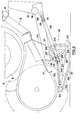
- the forage harvester is of the precision chop type and is generally of conventional construction, whereby it will only be described briefly.
- the machine comprises a base unit or chassis 1 fitted with a pair of ground-engaging wheels 2, and is of the pull.type, whereby a drawbar 3 and a drive shaft 4 (for connection to the power-take-off shaft of a tractor) are provided.
- a header 5 for the machine comprising a pick-up unit, is mounted via arms 8 on the base unit 1 for pivotal movement about a pivot shaft 6.
- the header 5 also comprises an auger 9 mounted for pivotal movement with the pick-up unit, the auger being operable to feed crop material received from the pick-up unit to a forward pair of feed rolls 11 which in turn feeds the crop material to a rear pair of feed rolls 12 from which the crop material is delivered to a cutterhead 13 having a conventional delivery spout 10 which is only partly shown in Figure 1.
- the header 5 is pivotally mounted on the base unit 1 so as to be movable to a raised, transport position (illustrated in Figure 3) in which the pick-up is clear of the ground.
- This raising and lowering is effected by an actuator 14 acting between the base unit 1 and one end of a bell-crank lever 15, the other end of which carries a roller 16 in engagement with the underside of a floor 17 of the header 5.
- the actuator 14 is retracted, the bell-crank lever 15 is pivoted clockwise about its pivot 18, whereby the end carrying the roller 16 is raised, carrying with it the header 5.
- Extension of the actuator 14 effects lowering of the header 5 to the operative position of Figures 1 and 2.
- the actuator 14 is coupled to the bell-crank lever 15 through a lost motion connection, enabling flotation of the header 5, when in the operative position, without effecting any retraction or extension of the plunger of the actuator 14.
- spring means may be provided between the chassis 1 and the bell-crank lever 15 to assist in the flotation of the header 5 over the ground contour.
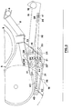
- the header 5 is fitted with a pair of retractable skids 19, one mounted towards each end thereof, to support the latter for movement at a substantially constant working height relative to the ground during operation of the machine.
- Each skid 19 comprises a cast shoe, the sole 21 of which is generally flat over the portion normally in contact with the ground during operation, and is formed with an upturned toe 22 and heel 23 so that they cannot dig into the ground when the shoe is in contact therewith.
- At the point of upturn of the heel 23 there is provided an integral transverse web 24 extending upwardly from the sole 21 and provided with a plurality of pairs of apertures 25 ( Figure 5).
- a central reinforcing web 26, also integral with the sole 21, is provided and this extends from the transverse web 25 to the toe 22.
- the sides of the sole 21 are upturned along a major portion of the latter.
- Each skid 19 carries a mounting bracket comprising two spaced, generally parallel side plates 27 interconnected at one end by a transverse plate 28.
- Each side plate 27 is formed with a two- limbed slot 29 generally resembling a figure seven and comprising a long limb 29' and a shorter limb 29", the former being disposed generally vertical and the latter generally horizontal.
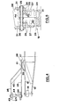
- the transverse plate 28 is formed with a plurality of pairs of elongated apertures 30, each pair being alignable with a selected pair of apertures 25 in the web 24, whereby these two components can be adjustably bolted together to set the desired working height of the header 5.
- the transverse plate 28 is extended beyond the upper edges of the side plates 27 and is turned over to provide a downwardly and forwardly extending portion 28'.
- the plates 27 are received between a pair of spaced, generally parallel plates 31 extending downwardly from the floor of the header 5, each plate 31 being formed with a two limbed slot 32 of the same shape as the slot 29 in the adjacent plate 27 but oriented as the mirror image of the latter.
- the two plates 31 are braced by a transverse plate 33, these transverse plate 33, these components forming a mounting bracket for the associated skid 19.
- Each skid is attached to the associated mounting bracket 31, 33 by a pivot pin 34 extending from outside one of the pair of plates 31 through the slot 32 therein, through the aligned slots 29 of the plates 27 and out through the slot 32 in the other of the pair of plates 31.
- Arms 35, 36 are pivotally retained on respective ends of the pin 34 by split pins, the arm 35 being straight and extending rearwardly to a mounting bracket 37 provided on the lower limb of the bellcrank lever 15 which, as seen in Figure 4, is formed from two spaced components 15' between which the roller 16 is mounted.
- the arm 36 first extends parallel to the arm 35 and is then cranked towards the latter and attached thereto short of the rear end of the arm 35.
- the cranked portion of the arm 36 is reinforced by a fillet 40.
- the end of the arm 35 extending rearwardly beyond the arm 36 is formed with a slot 38 which receives a bolt 41 inserted through an aperture 39 in the mounting bracket 37.
- the slot 38 provides a lost motion connection for the arms 35, 36 to the bracket 37 for a reason to be described.
- the toe 22 of each skid 19 is pivotally attached to a bracket 42 on the header 5, and a tension spring 43 acts between the forward end of the web 26 and a bracket 44 carried by the pivot pin 34.
- each skid 19 is disposed intermediate the ends of the slot 38, although towards the forward end thereof, when the header 5 is in the operative position.
- the skids 19 follow the contour of the ground and if any rise ie encountered, the skids will ride up it and lift the header accordingly about the pivot shaft 6 through the agencies of the pivot pins 34 and the toe pivots.
- the header 5 When the forage harvester is to be transported without being operative, the header 5 is raised to the transport position of Figure 3 by retracting the actuator 14 as already described. This results in the header being pivoted upwardly about the pivot shaft 6. This movement pulls the arms 35 and 56 generally forwardly of the machine first without any consequential movement until the bolts 41 engage the rear ends of the slots 38 in the arms 35 at which point the pivot pins 34 are then pulled rearwardly and as a result, first travel along the shorter limbs 29", 32" of the slots 29, 32 to unlock the skids from the operative position, and then ride up the longer limbs 29' and 32' until the outer ends of the latter are engaged.
- the plates 27 are raised relative to the plates 31 and hence the skids 19 are retracted or raised relative to the header 5.
- the skids 19 are raised to substantially the same ground clearance height as the header 5 (typically 10 inches/25 centimetres), whereby no problems arise during transport such as the fouling of the ground or objects thereon by the skids which is often a problem with non-rectractable skids which have been employed to date, unless arrangements have been made to lift the header 5 still further to give the necessary skid clearance.
- this extra raising on the header 5 can adversely affect the working relationship of the auger 9 and the feed rolls 11 which is critical for efficient operation of the machine.
- the tension springs 43 are extended and when the header 5 is lowered on extension of the actuator 14, the springs 43 serve to ensure that the skids are returned to their operative positions by contracting and pulling on the pivot pins 34 to urge the same back down the limbs 29', 32' and into the "locking" limbs 29", 32" of the slots 29 and 32.
- skid retraction, lowering and locking is achieved automatically on raising and lowering the header 5, respectively.
- the present invention provides retractable skids to overcome the problem with known skids of inadequate ground clearance in the transport position.
- retraction of the skids is achieved in a simple but effective manner which does not involve any significant increase in manufacturing costs. It is not necessary for automatic retraction and lowering of the skids to be effected on raising and lowering the pick-up unit but this is a convenient and generally desirable arrangement.
- the invention is applicable to any a c ;ricultural machine employing skids and is not limited to forage harvesters.
Landscapes
- Life Sciences & Earth Sciences (AREA)
- Environmental Sciences (AREA)
- Agricultural Machines (AREA)
Applications Claiming Priority (2)
| Application Number | Priority Date | Filing Date | Title |
|---|---|---|---|
| GB838307442A GB8307442D0 (en) | 1983-03-17 | 1983-03-17 | Agricultural machines |
| GB8307442 | 1983-03-17 |
Publications (3)
| Publication Number | Publication Date |
|---|---|
| EP0120531A2 true EP0120531A2 (de) | 1984-10-03 |
| EP0120531A3 EP0120531A3 (en) | 1985-01-23 |
| EP0120531B1 EP0120531B1 (de) | 1988-01-07 |
Family
ID=10539765
Family Applications (1)
| Application Number | Title | Priority Date | Filing Date |
|---|---|---|---|
| EP19840200364 Expired EP0120531B1 (de) | 1983-03-17 | 1984-03-14 | Kufe für landwirtschaftliche Maschinen |
Country Status (3)
| Country | Link |
|---|---|
| EP (1) | EP0120531B1 (de) |
| DE (1) | DE3468306D1 (de) |
| GB (1) | GB8307442D0 (de) |
Cited By (1)
| Publication number | Priority date | Publication date | Assignee | Title |
|---|---|---|---|---|
| EP4552471A1 (de) * | 2023-11-09 | 2025-05-14 | CNH Industrial Belgium N.V. | Gras pickup erntevorsatz |
Family Cites Families (2)
| Publication number | Priority date | Publication date | Assignee | Title |
|---|---|---|---|---|
| AT239585B (de) * | 1961-01-11 | 1965-04-12 | Bautz Gmbh Josef | Erntemaschine mit einer an dem Maschinengestell schwenkbar gelagerten Aufnahmeeinrichtung |
| US3925971A (en) * | 1974-03-15 | 1975-12-16 | Hesston Corp | Gauging apparatus for implement head |
-
1983
- 1983-03-17 GB GB838307442A patent/GB8307442D0/en active Pending
-
1984
- 1984-03-14 EP EP19840200364 patent/EP0120531B1/de not_active Expired
- 1984-03-14 DE DE8484200364T patent/DE3468306D1/de not_active Expired
Cited By (1)
| Publication number | Priority date | Publication date | Assignee | Title |
|---|---|---|---|---|
| EP4552471A1 (de) * | 2023-11-09 | 2025-05-14 | CNH Industrial Belgium N.V. | Gras pickup erntevorsatz |
Also Published As
| Publication number | Publication date |
|---|---|
| GB8307442D0 (en) | 1983-04-27 |
| DE3468306D1 (en) | 1988-02-11 |
| EP0120531B1 (de) | 1988-01-07 |
| EP0120531A3 (en) | 1985-01-23 |
Similar Documents
| Publication | Publication Date | Title |
|---|---|---|
| US4573309A (en) | Pull-type windrower | |
| US4590751A (en) | Double windrowing attachment for harvester | |
| US5243810A (en) | Header transport system | |
| US7347277B2 (en) | Self contained transport for crop harvesting header | |
| EP0356913B1 (de) | Erntemaschine | |
| US4607996A (en) | Lateral transport trailer | |
| US6073431A (en) | Self-propelled windrower | |
| US4662161A (en) | Pull-type windrower | |
| EP0406766A1 (de) | Mähmaschine | |
| US3958399A (en) | Header attachment structure | |
| US4934131A (en) | Pull type swather frame | |
| US6511279B1 (en) | Automatic fold-up jack for an implement transporter | |
| AU2006246475B2 (en) | Self contained transport for harvesting header | |
| CA1318137C (en) | Swather attachment for bi-directional tractor | |
| EP0120531B1 (de) | Kufe für landwirtschaftliche Maschinen | |
| US6485246B1 (en) | Apparatus for raising ramps on an implement transporter | |
| US4058958A (en) | Method and means for converting a crop pickup on a crop processing machine between field and transport modes | |
| US12035646B2 (en) | Integrated transport coupling system | |
| GB1583983A (en) | Harvesting machines | |
| US3714767A (en) | Crop harvester | |
| CA1300899C (en) | Pull type swather | |
| US6514030B1 (en) | Ramp locks for an implement transporter | |
| EP0507408B2 (de) | Landwirtschaftliche Maschine | |
| EP0119659B1 (de) | Feldhäcksler | |
| US3716976A (en) | Crop harvester |
Legal Events
| Date | Code | Title | Description |
|---|---|---|---|
| PUAI | Public reference made under article 153(3) epc to a published international application that has entered the european phase |
Free format text: ORIGINAL CODE: 0009012 |
|
| 17P | Request for examination filed |
Effective date: 19840314 |
|
| AK | Designated contracting states |
Designated state(s): DE FR GB |
|
| PUAL | Search report despatched |
Free format text: ORIGINAL CODE: 0009013 |
|
| AK | Designated contracting states |
Designated state(s): DE FR GB |
|
| 17Q | First examination report despatched |
Effective date: 19860606 |
|
| RAP1 | Party data changed (applicant data changed or rights of an application transferred) |
Owner name: NEW HOLLAND N.V. |
|
| GRAA | (expected) grant |
Free format text: ORIGINAL CODE: 0009210 |
|
| AK | Designated contracting states |
Kind code of ref document: B1 Designated state(s): DE FR GB |
|
| REF | Corresponds to: |
Ref document number: 3468306 Country of ref document: DE Date of ref document: 19880211 |
|
| ET | Fr: translation filed | ||
| RAP4 | Party data changed (patent owner data changed or rights of a patent transferred) |
Owner name: FORD NEW HOLLAND N.V. |
|
| PLBE | No opposition filed within time limit |
Free format text: ORIGINAL CODE: 0009261 |
|
| STAA | Information on the status of an ep patent application or granted ep patent |
Free format text: STATUS: NO OPPOSITION FILED WITHIN TIME LIMIT |
|
| 26N | No opposition filed | ||
| PGFP | Annual fee paid to national office [announced via postgrant information from national office to epo] |
Ref country code: DE Payment date: 19920111 Year of fee payment: 9 |
|
| PGFP | Annual fee paid to national office [announced via postgrant information from national office to epo] |
Ref country code: FR Payment date: 19920114 Year of fee payment: 9 |
|
| PGFP | Annual fee paid to national office [announced via postgrant information from national office to epo] |
Ref country code: GB Payment date: 19920303 Year of fee payment: 9 |
|
| PG25 | Lapsed in a contracting state [announced via postgrant information from national office to epo] |
Ref country code: GB Effective date: 19930314 |
|
| GBPC | Gb: european patent ceased through non-payment of renewal fee |
Effective date: 19930314 |
|
| PG25 | Lapsed in a contracting state [announced via postgrant information from national office to epo] |
Ref country code: FR Effective date: 19931130 |
|
| PG25 | Lapsed in a contracting state [announced via postgrant information from national office to epo] |
Ref country code: DE Effective date: 19931201 |
|
| REG | Reference to a national code |
Ref country code: FR Ref legal event code: ST |