EP0120473A2 - Numerical control apparatus for machine tools - Google Patents
Numerical control apparatus for machine tools Download PDFInfo
- Publication number
- EP0120473A2 EP0120473A2 EP84103179A EP84103179A EP0120473A2 EP 0120473 A2 EP0120473 A2 EP 0120473A2 EP 84103179 A EP84103179 A EP 84103179A EP 84103179 A EP84103179 A EP 84103179A EP 0120473 A2 EP0120473 A2 EP 0120473A2
- Authority
- EP
- European Patent Office
- Prior art keywords
- command
- circuit
- control apparatus
- numerical control
- work
- Prior art date
- Legal status (The legal status is an assumption and is not a legal conclusion. Google has not performed a legal analysis and makes no representation as to the accuracy of the status listed.)
- Granted
Links
Images


Classifications
-
- G—PHYSICS
- G05—CONTROLLING; REGULATING
- G05B—CONTROL OR REGULATING SYSTEMS IN GENERAL; FUNCTIONAL ELEMENTS OF SUCH SYSTEMS; MONITORING OR TESTING ARRANGEMENTS FOR SUCH SYSTEMS OR ELEMENTS
- G05B19/00—Programme-control systems
- G05B19/02—Programme-control systems electric
- G05B19/18—Numerical control [NC], i.e. automatically operating machines, in particular machine tools, e.g. in a manufacturing environment, so as to execute positioning, movement or co-ordinated operations by means of programme data in numerical form
- G05B19/414—Structure of the control system, e.g. common controller or multiprocessor systems, interface to servo, programmable interface controller
- G05B19/4147—Structure of the control system, e.g. common controller or multiprocessor systems, interface to servo, programmable interface controller characterised by using a programmable interface controller [PIC]
-
- G—PHYSICS
- G05—CONTROLLING; REGULATING
- G05B—CONTROL OR REGULATING SYSTEMS IN GENERAL; FUNCTIONAL ELEMENTS OF SUCH SYSTEMS; MONITORING OR TESTING ARRANGEMENTS FOR SUCH SYSTEMS OR ELEMENTS
- G05B19/00—Programme-control systems
- G05B19/02—Programme-control systems electric
- G05B19/18—Numerical control [NC], i.e. automatically operating machines, in particular machine tools, e.g. in a manufacturing environment, so as to execute positioning, movement or co-ordinated operations by means of programme data in numerical form
- G05B19/408—Numerical control [NC], i.e. automatically operating machines, in particular machine tools, e.g. in a manufacturing environment, so as to execute positioning, movement or co-ordinated operations by means of programme data in numerical form characterised by data handling or data format, e.g. reading, buffering or conversion of data
-
- G—PHYSICS
- G05—CONTROLLING; REGULATING
- G05B—CONTROL OR REGULATING SYSTEMS IN GENERAL; FUNCTIONAL ELEMENTS OF SUCH SYSTEMS; MONITORING OR TESTING ARRANGEMENTS FOR SUCH SYSTEMS OR ELEMENTS
- G05B2219/00—Program-control systems
- G05B2219/30—Nc systems
- G05B2219/34—Director, elements to supervisory
- G05B2219/34069—Shared memory
-
- G—PHYSICS
- G05—CONTROLLING; REGULATING
- G05B—CONTROL OR REGULATING SYSTEMS IN GENERAL; FUNCTIONAL ELEMENTS OF SUCH SYSTEMS; MONITORING OR TESTING ARRANGEMENTS FOR SUCH SYSTEMS OR ELEMENTS
- G05B2219/00—Program-control systems
- G05B2219/30—Nc systems
- G05B2219/34—Director, elements to supervisory
- G05B2219/34319—Sequence as function of nc controlled axis position, axis zone
-
- G—PHYSICS
- G05—CONTROLLING; REGULATING
- G05B—CONTROL OR REGULATING SYSTEMS IN GENERAL; FUNCTIONAL ELEMENTS OF SUCH SYSTEMS; MONITORING OR TESTING ARRANGEMENTS FOR SUCH SYSTEMS OR ELEMENTS
- G05B2219/00—Program-control systems
- G05B2219/30—Nc systems
- G05B2219/50—Machine tool, machine tool null till machine tool work handling
- G05B2219/50358—Work handling, automatic load unload workpiece
Abstract
Description
- The present invention relates to numerical control apparatus (hereinafter referred to as NC apparatus).
- Figure 1 of the accompanying drawings is a block diagram showing the arrangement of an NC apparatus. The drawing shows a tape 1 in which a work program is stored using a special NC language, a
reading circuit 2, abuffer memory 3, acommand decoding circuit 4,precalculation circuit 5, acontrol circuit 6, a shaft-displacementamount output circuit 7, apulse distribution circuit 8, aservo unit 9, amotor 10, adetector 11, aspindle rotation detector 12, a programmable controller 13 (hereinafter referred to as a PC), and amachine tool 14 to be controlled. - The NC apparatus is constituted by the
reading circuit 2, thebuffer memory 3, thecommand decoding circuit 4, theprecalculation circuit 5, thecontrol circuit 6, and the shaft-displacementamount output circuit 7. Sometimes the apparatus is said to include thepulse distribution circuit 8. As such an NC apparatus, the product MELDAS-L1 produced by Mitsubishi Electric Corporation of Japan, the products FANUC-3T and FANUC-6T produced by Fanuc Co. of Japan, and the products SINUMERIK-3T and SINUMERIK-8T produced by Siemens AG of West Germany are known. - The operation of such an NC apparatus will be described in brief. The content of the program stored on the tape 1 is read out by the
reading circuit 2 and stored in thebuffer memory 3. Then, the program is decoded by thecommand decoding circuit 4 and subjected to preprocessing by theprecalculation circuit 5. The resultant data of calculation is transferred to the nextstage control circuit 6 to perform on-line control. That is, the amount of shaft displacement of themachine tool 14 is instructed by blocks of data of applied to the shaft-displacementamount output circuit 7 so as to cause thepulse distribution circuit 8 to actuate theservo unit 9 to drive themotor 10 to move the shaft of themachine tool 14. Thedetector 11 is attached to themotor 10 to detect the amount of rotation of themotor 10. The output of the -detector 11 is fed back to theservo unit 9 to drive themotor 10 by a predetermined amount. Thespindle rotation detector 12 is attached to spindle for the purpose of detecting the rotary speed of a rotating workpiece or a rotating tool. The output of the spindle is fed back to thepulse distribution circuit 8 and there used to synchronize the rotary speed of themotor 10 with that of the spindle. - The contents of the program on the tape 1 read by the
reading circuit 2 include M-commands, S-commands, T-commands, etc. The M-command indicates control commands except a command instructing the displacement of a tool rest of the machine tool to be controlled, a command instructing the selection of cutting tool, and a command instructing the number of revolutions of the spindle. For instance, 100 different commands M00 to M99 are defined by Japanese Industrial Standard No. ISO-R1056. The S-command is used for instructing the speed of the spindle, and is expressed as, for example, -S1500 which instructs a spindle speed of 1500 r.p.m. The T-command is a command instructing the selection of one out of a plurality of cutting tools mounted on a tool support. Generally, a plurality of cutting tools are mounted on a polygonal tool support which is rotatable so as to make the instructed cutting tool available. The T-command is expressed as, for example, TO1 which instructs to select No. 1 cutting tool. - The PC 13 is a sequencer used for performing control, such as oil pressure control, control relating to auxiliary function such as tool replacement, spindle drive, etc., that is, control functions except the control of shaft drive of the
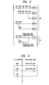
machine tool 14, and is arranged to exchange signals with thecontrol circuit 6 to perform the above-mentioned control. That is, the PC 13 decodes M-, S-, T-commands provided by thecontrol circuit 6 and produces signals which are applied as control signals to operating units for the machine tool in accordance with a predetermined sequence. In response to the control signals, mechanical operations of the machine tool are performed and thecontrol circuit 6 is informed of the completion of execution of commands upon the detection of the mechanical operations. - Details of the operations of the PC 13 will be described. The description is made here with respect to the case where "COOLANT OIL ON" (M08) and "COOLANT OIL OFF" (M09) are given as control signals from the
control circuit 6. Fig. 2 is a diagram showing a relay circuit for causing the operation of the above-mentioned commands to be performed. This circuit is realized by a program in the PC 13. In Fig. 2reference numeral 20 designates a decoder circuit for the commands M08 and M09 from thecontrol circuit M *8,M *4,M *2, and M*l designate contacts respectively corresponding to the commands M8, M4, M2, and Ml issued from the NC apparatus. The PC 13 decodes the commands M08 and M09 and provides its output to the machine side as shown in Fig. 3 to thereby perform "COOLANT OIL ON" and "COOLANT OIL OFF" operations. - In the conventional NC apparatus, however, the M-command, S-command, T-command, and the like are applied to the PC 13 unidirectionally from the work program of the tape 1.
- Further., recently it has been understood that (1) it is desirable to refer to the data in the
PC 13 from the work program side", and (2) it is desirable to issue more commands to thePC 13 from the work program side. However, there has been no NC apparatus provided with effective means for satisfying these requirements. - That is, there are new requirements for robot combination, automatic work measurement, tool life management etc. An NC apparatus which can meet such requirements is needed. To provide such an apparatus, it is necessary to expand the interface function with external devices such as machines measuring units, etc.
- Although the command instructing the displacing of the tool support of the machine tool is transmitted to the pulse distribution circuit and the servo unit through the shaft-displacement
amount output circuit 7, the PC 13 is used as an interface with the machine side for all other commands, and therefore it is convenient to achieve through the PC the above-mentioned expansion of the interface function. - Accordingly, the above-mentioned data at the
PC 13 side is applied to external devices such as machines, measuring devices, etc., and in the case where an automatized system is employed in which, for example, a workpiece on which work has been completed is transported from the machine tool to an automatic measuring device using a handling robot and the NC apparatus receives the result of measurement to feed it back as a correction data for the next workpiece, the following are required: - (1) output of an operating command (displacement amount if necessary) to the handling robot;
- (2) output of a measurement start command to the measuring device; and
- (3) input of data of measurement result, etc.
- Thus, there is a requirement for the data at the PC 13 side to be accessible from the work program side so as to increase the number of commands issued from the work program side to the PC 13.
- The present invention has been attained in view of the above-mentioned circumstance.
- An object thereof is to provide an NC apparatus having a control function covering a wide range.
- Another object of the present invention is to provide an NC apparatus in which the management and use of the control program can be easily performed.
- A further object of the present invention is to provide an NC-apparatus in which when different work is to be performed, the work can be achieved merely by changing data without replacing the work program.
- To attain the objects as described above, an NC apparatus according to the present invention is characterized in that a common data register group is provided so that reading/writing can be commonly performed by the work program as well as by the programmable controller.
- For a better understanding of the invention, and to show how the same may be carried into effect, reference will now be made, by way of example, to the accompanying drawings, in which:
- Fig. 1 is a block diagram showing the arrangement of an NC apparatus;
- Fig. 2 and 3 are relay circuit programs used for explaining the operation of a PC used in the NC apparatus of Fig. 1;
- Fig. 4 is a block diagram of a preferred embodiment of an NC apparatus of the present invention;
- Fig. 5 is a flowchart used for explaining the execution of variable command processing;
- Fig. 6 is a flowchart used for explaining the operation of the programmable controller; and
- Fig. 7 is a flowchart used for explaining a main part of a PC according to the present invention.
- Referring to the drawings, a preferred embodiment of the present invention will now be described.
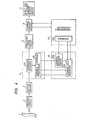
- Fig. 4 is a block diagram of a primary part of a numerical control- apparatus constructed in accordance with the present invention. In Fig. 4, 4A and 4B designate a command decoder and a variable command processor, respectively, both of which are provided in the command
decoding processing circuit 4. A commondata register group 15, constituted by two or morecommon data registers 15A and anaddress decoding circuit 15B, employs a dual-port random access memory so that the reading/writing of the data therein can be performed by thevariable command processor 4B. Further, an interface 13A is provided in thePC 13 so that the reading/writing of common data can be performed through the interface 13A. - The arrangement of the remaining portions of the apparatus is the same as that of Fig. 1 and therefore a further description thereof is omitted.
- The operation of the apparatus of the preferred embodiment will now be described.
- It is assumed that the work program command used to set numerical data "dn" into the n-th register of the common
data register group 15 is "Ln = dn". Upon the reception of this command, thecommand decoder 4A transfers the processing to thevariable command processor 4B. In response to the numeral value "n" (which is address designation data), following the Roman character "L", thevariable command decoder 4B writes the numerical data "dn" into the n-th register in the commondata register group 15. - It is determined that, when the content of the m-th register of the common
data register group 15 is used as the numerical data of the work program, "Lm" is instructed in the numerical value portion following the address character in the NC work program. For example, when the content of the m-th register is used in place of the X-axis command value "100" in "G00 X 100", the work program command is "G00 X Lm". Upon the reception of the above-mentioned command, thecommand decoder 4A transfers the processing to thevariable command processor 4B. With the numerical value "m" following the character "L" as the address designation data, the content of the m-th register of the commondata register group 15 is read and substituted for the numerical data of the address "X" of the above-mentioned program command "GOO X Lm". - Next, the
PC 13 reads the contents of the p-th register of the commondata register group 15 at a predetermined time and sets -the data "dq" into the q-th register of the commondata register group 15 or the contents "dr" of the r-th register is read out therefrom depending on the read-out content of the p-th register. - Fig. 5 is a flowchart showing the operation of the
variable processor 4B. In this Figure, the program command "Ln = dl" or GOO X Lm" containing the character "L" in the work program is received through the command buffer from thecommand processing portion 4A. Accordingly, it can be determined that in the case where the character "L" is set at the head of the command buffer, the command is "Ln = dl", while in the case where the character "L" is not so set, the command is "G00 X Lm". - Fig. 6 is a flowchart showing the operation of the
PC 13. Data is synchronously exchanged between thePC 13 and each of themachine tools 14 and thecontrol circuit 6. Fig. 7 is a flowchart of a main part of thePC 13 in accordance with the present invention. This operations specified by this flowchart are carried out in the data processor indicated in Fig. 6. The commondata register group 15 can be accessed from the work program side as well as thePC 13 side, and hence control functions covering a .wider range than those of the conventional NC apparatus can be realized by arranging in advance the uses of the individual registers of the commondata register group 15 between the work program forming side and thePC 13 side. - For example, in the case where a .handling robot associated with a machine tool for attaching/removing/conveying a workpiece is caused to operate at the. beginning and end of the work, conventionally, data indicating the amount and speed of displacement of the handling robot is stored in a control device of the handling robot and the operation start timing is issued from an NC apparatus at the machine tool side. In -the conventional system, however, there is a problem that it is necessary to change both the work program and the program stored in the handling robot every time the work to be effected changes so that the management and practical use of the program are very troublesome. According to the present invention, however, it is sufficient to effect the management and practical use of only the work program for all types of work because not only the operating start signal, but also the amount and speed of displacement of the handling robot can be issued from the work program to the control device for the handling robot through the
PC 13. - As described above, the NC apparatus according to the present invention is provided with a common
data register group 15 including two or more registers and is arranged so that writing and reading can be carried out from the work program side as well as the PC side. The invention is therefore advantageous in that-control functions covering a wider range than could be obtained with the conventional NC apparatus are attainable. - Thus, broadly expressed, the present invention provides numerical control apparatus in which writing/reading can be commonly performed both from a work program and from a programmable controller.
Claims (10)
Applications Claiming Priority (2)
| Application Number | Priority Date | Filing Date | Title |
|---|---|---|---|
| JP58050105A JPS59174916A (en) | 1983-03-25 | 1983-03-25 | Numerical control device |
| JP50105/83 | 1983-03-25 |
Publications (3)
| Publication Number | Publication Date |
|---|---|
| EP0120473A2 true EP0120473A2 (en) | 1984-10-03 |
| EP0120473A3 EP0120473A3 (en) | 1986-09-17 |
| EP0120473B1 EP0120473B1 (en) | 1991-05-29 |
Family
ID=12849796
Family Applications (1)
| Application Number | Title | Priority Date | Filing Date |
|---|---|---|---|
| EP84103179A Revoked EP0120473B1 (en) | 1983-03-25 | 1984-03-22 | Numerical control apparatus for machine tools |
Country Status (4)
| Country | Link |
|---|---|
| US (1) | US4584638A (en) |
| EP (1) | EP0120473B1 (en) |
| JP (1) | JPS59174916A (en) |
| DE (1) | DE3484629D1 (en) |
Families Citing this family (8)
| Publication number | Priority date | Publication date | Assignee | Title |
|---|---|---|---|---|
| JPS6093511A (en) * | 1983-10-27 | 1985-05-25 | Fanuc Ltd | Format conversion interface device |
| JPS61163405A (en) * | 1985-01-16 | 1986-07-24 | Mitsubishi Electric Corp | Numerical control device |
| DE3518792A1 (en) * | 1985-05-24 | 1986-11-27 | Traub Gmbh, 7313 Reichenbach | NUMERICALLY CONTROLLED LATHE |
| JPH0695290B2 (en) * | 1987-02-21 | 1994-11-24 | フアナツク株式会社 | Interface method in numerical control device |
| JPH0782378B2 (en) * | 1987-04-10 | 1995-09-06 | 三菱電機株式会社 | Numerical control device |
| JPS6425208A (en) * | 1987-07-21 | 1989-01-27 | Fanuc Ltd | Numerical controller |
| JPS6462709A (en) * | 1987-09-02 | 1989-03-09 | Fanuc Ltd | Spindle control system |
| JP2522047B2 (en) * | 1988-08-03 | 1996-08-07 | 三菱電機株式会社 | Programmable controller for device control |
Citations (3)
| Publication number | Priority date | Publication date | Assignee | Title |
|---|---|---|---|---|
| EP0041336A1 (en) * | 1980-05-28 | 1981-12-09 | Fanuc Ltd. | Numerical control device |
| EP0074412A1 (en) * | 1981-03-23 | 1983-03-23 | Fanuc Ltd. | Numerical control system |
| EP0091774A1 (en) * | 1982-04-07 | 1983-10-19 | Fanuc Ltd. | Numerical control |
Family Cites Families (9)
| Publication number | Priority date | Publication date | Assignee | Title |
|---|---|---|---|---|
| JPS51130781A (en) * | 1975-05-09 | 1976-11-13 | Toyoda Mach Works Ltd | Group controlling system |
| JPS5316176A (en) * | 1976-07-30 | 1978-02-14 | Toshiba Corp | Nc device loaded with sequential controller |
| US4200936A (en) * | 1976-08-17 | 1980-04-29 | Cincinnati Milacron Inc. | Asynchronous bidirectional direct serial interface linking a programmable machine function controller and a numerical control |
| JPS6016664B2 (en) * | 1977-10-28 | 1985-04-26 | 豊田工機株式会社 | data transfer device |
| JPS54117883A (en) * | 1978-03-06 | 1979-09-12 | Okuma Mach Works Ltd | Numerical control device |
| JPS5621794A (en) * | 1979-07-30 | 1981-02-28 | Fujitsu Fanuc Ltd | Controlling system for industrial robot |
| JPS5636709A (en) * | 1979-09-04 | 1981-04-10 | Fanuc Ltd | Numerical control system |
| JPS56108109A (en) * | 1980-02-01 | 1981-08-27 | Fanuc Ltd | Programmable sequence controller |
| JPS57157304A (en) * | 1981-03-23 | 1982-09-28 | Fanuc Ltd | Numerical control system |
-
1983
- 1983-03-25 JP JP58050105A patent/JPS59174916A/en active Granted
-
1984
- 1984-03-22 EP EP84103179A patent/EP0120473B1/en not_active Revoked
- 1984-03-22 DE DE8484103179T patent/DE3484629D1/en not_active Revoked
- 1984-03-23 US US06/592,501 patent/US4584638A/en not_active Expired - Lifetime
Patent Citations (3)
| Publication number | Priority date | Publication date | Assignee | Title |
|---|---|---|---|---|
| EP0041336A1 (en) * | 1980-05-28 | 1981-12-09 | Fanuc Ltd. | Numerical control device |
| EP0074412A1 (en) * | 1981-03-23 | 1983-03-23 | Fanuc Ltd. | Numerical control system |
| EP0091774A1 (en) * | 1982-04-07 | 1983-10-19 | Fanuc Ltd. | Numerical control |
Also Published As
| Publication number | Publication date |
|---|---|
| JPH0457005B2 (en) | 1992-09-10 |
| JPS59174916A (en) | 1984-10-03 |
| US4584638A (en) | 1986-04-22 |
| EP0120473B1 (en) | 1991-05-29 |
| DE3484629D1 (en) | 1991-07-04 |
| EP0120473A3 (en) | 1986-09-17 |
Similar Documents
| Publication | Publication Date | Title |
|---|---|---|
| CA1243380A (en) | Method and apparatus for producing numerical control programs | |
| US4396987A (en) | Machine tool and robot control apparatus | |
| US5252899A (en) | Numerical control system | |
| EP0188621B1 (en) | Numerical control system | |
| US4245316A (en) | System for providing time control data in a numerical control system | |
| JPS5611510A (en) | Numerical control system | |
| US4631684A (en) | Tool support synchronizing system for numerical control apparatus | |
| EP0120473B1 (en) | Numerical control apparatus for machine tools | |
| US4404506A (en) | Tool position offsetting system for a spare tool | |
| EP0173745A1 (en) | Tool display system for an automatic tool exchanger | |
| EP0397886B1 (en) | Cnc control system | |
| US4517657A (en) | Integrated bit processor/word processor control system | |
| JPH0819939A (en) | Monitor for machining load | |
| US5313402A (en) | Midway start method in numerical control system | |
| US5010285A (en) | Numerical control system | |
| KR920004080B1 (en) | Numerical control device | |
| EP0107794B1 (en) | Numerical control system | |
| KR920003748B1 (en) | Numerical control device | |
| EP0270678B1 (en) | Apparatus for processing numerical control program | |
| US5331540A (en) | Symbol definition system and method a programmable machine controller | |
| US4569013A (en) | Spindle speed control method and apparatus | |
| US5130919A (en) | Industrial machine control device for monitoring mechanical coordinate data of a controlled machine | |
| KR910009240B1 (en) | Numerical controller | |
| US5159251A (en) | Position correcting system for different workpiece machining positions | |
| KR830002110B1 (en) | Sequence control method of numerical machine tool |
Legal Events
| Date | Code | Title | Description |
|---|---|---|---|
| PUAI | Public reference made under article 153(3) epc to a published international application that has entered the european phase |
Free format text: ORIGINAL CODE: 0009012 |
|
| AK | Designated contracting states |
Designated state(s): DE FR GB |
|
| PUAL | Search report despatched |
Free format text: ORIGINAL CODE: 0009013 |
|
| AK | Designated contracting states |
Kind code of ref document: A3 Designated state(s): DE FR GB |
|
| 17P | Request for examination filed |
Effective date: 19870309 |
|
| 17Q | First examination report despatched |
Effective date: 19880913 |
|
| GRAA | (expected) grant |
Free format text: ORIGINAL CODE: 0009210 |
|
| AK | Designated contracting states |
Kind code of ref document: B1 Designated state(s): DE FR GB |
|
| REF | Corresponds to: |
Ref document number: 3484629 Country of ref document: DE Date of ref document: 19910704 |
|
| ET | Fr: translation filed | ||
| PLBI | Opposition filed |
Free format text: ORIGINAL CODE: 0009260 |
|
| 26 | Opposition filed |
Opponent name: N.V. PHILIPS' GLOEILAMPENFABRIEKEN Effective date: 19920302 |
|
| PGFP | Annual fee paid to national office [announced via postgrant information from national office to epo] |
Ref country code: FR Payment date: 19930309 Year of fee payment: 10 |
|
| PLAB | Opposition data, opponent's data or that of the opponent's representative modified |
Free format text: ORIGINAL CODE: 0009299OPPO |
|
| R26 | Opposition filed (corrected) |
Opponent name: GRUNDIG AKTIENGESELLSCHAFT Effective date: 19920302 |
|
| PG25 | Lapsed in a contracting state [announced via postgrant information from national office to epo] |
Ref country code: FR Effective date: 19941130 |
|
| REG | Reference to a national code |
Ref country code: FR Ref legal event code: ST |
|
| REG | Reference to a national code |
Ref country code: GB Ref legal event code: 746 Effective date: 19951107 |
|
| PGFP | Annual fee paid to national office [announced via postgrant information from national office to epo] |
Ref country code: GB Payment date: 19970313 Year of fee payment: 14 |
|
| PLAB | Opposition data, opponent's data or that of the opponent's representative modified |
Free format text: ORIGINAL CODE: 0009299OPPO |
|
| PLBQ | Unpublished change to opponent data |
Free format text: ORIGINAL CODE: EPIDOS OPPO |
|
| PGFP | Annual fee paid to national office [announced via postgrant information from national office to epo] |
Ref country code: DE Payment date: 19970401 Year of fee payment: 14 |
|
| R26 | Opposition filed (corrected) |
Opponent name: DR. JOHANNES HEIDENHAIN GMBH Effective date: 19920302 |
|
| APAC | Appeal dossier modified |
Free format text: ORIGINAL CODE: EPIDOS NOAPO |
|
| RDAH | Patent revoked |
Free format text: ORIGINAL CODE: EPIDOS REVO |
|
| RDAG | Patent revoked |
Free format text: ORIGINAL CODE: 0009271 |
|
| STAA | Information on the status of an ep patent application or granted ep patent |
Free format text: STATUS: PATENT REVOKED |
|
| 27W | Patent revoked |
Effective date: 19971002 |
|
| GBPR | Gb: patent revoked under art. 102 of the ep convention designating the uk as contracting state |
Free format text: 971002 |
|
| APAH | Appeal reference modified |
Free format text: ORIGINAL CODE: EPIDOSCREFNO |