EP0119643A2 - Liquid distributing apparatus and method for a liquid-vapor contact column - Google Patents
Liquid distributing apparatus and method for a liquid-vapor contact column Download PDFInfo
- Publication number
- EP0119643A2 EP0119643A2 EP84200188A EP84200188A EP0119643A2 EP 0119643 A2 EP0119643 A2 EP 0119643A2 EP 84200188 A EP84200188 A EP 84200188A EP 84200188 A EP84200188 A EP 84200188A EP 0119643 A2 EP0119643 A2 EP 0119643A2
- Authority
- EP
- European Patent Office
- Prior art keywords
- liquid
- opening
- drip
- openings
- distributor
- Prior art date
- Legal status (The legal status is an assumption and is not a legal conclusion. Google has not performed a legal analysis and makes no representation as to the accuracy of the status listed.)
- Withdrawn
Links
Images


Classifications
-
- B—PERFORMING OPERATIONS; TRANSPORTING
- B01—PHYSICAL OR CHEMICAL PROCESSES OR APPARATUS IN GENERAL
- B01D—SEPARATION
- B01D3/00—Distillation or related exchange processes in which liquids are contacted with gaseous media, e.g. stripping
- B01D3/008—Liquid distribution
-
- B—PERFORMING OPERATIONS; TRANSPORTING
- B01—PHYSICAL OR CHEMICAL PROCESSES OR APPARATUS IN GENERAL
- B01D—SEPARATION
- B01D3/00—Distillation or related exchange processes in which liquids are contacted with gaseous media, e.g. stripping
- B01D3/14—Fractional distillation or use of a fractionation or rectification column
- B01D3/16—Fractionating columns in which vapour bubbles through liquid
- B01D3/18—Fractionating columns in which vapour bubbles through liquid with horizontal bubble plates
- B01D3/20—Bubble caps; Risers for vapour; Discharge pipes for liquid
Definitions
- This invention relates to a method and apparatus for uniformly distributing a downflowing liquid in a liquid-vapor contact tower.
- liquid "distributor” does not collect liquid droplets falling randomly from sources located above the distributor in the tower such as from a tower packing while a liquid redistributor does.
- the liquid "distributor” is usually known as only being capable of distributing liquid which is fed directly to it while the liquid “redistributor” is known as being capable of performing this function in addition to collecting maldistributed liquid falling from above and uniformly distributing both sources of liquid.
- liquid distributors and liquid redistributors will be used interchangeably herein, and the term “liquid distributing apparatus” will be used herein as meaning either liquid distributors or liquid redistributors, or both.
- a trough-type distributor is one which employs a plurality of spaced troughs, having closed ends and which are usually arranged in a parallel relationship. Liquid is usually fed to these troughs from one or more so-called "parting boxes” or “splitters” located above the troughs. Located in the sides of such troughs are triangular or rectangular weirs. The bottoms of these weirs are usually located at the same horizontal height when the distributor is installed in a tower. Gas rising in the tower is allowed to pass between the spaced troughs while liquid falls from the weirs.
- a representative example of such weir-type distributors can be found in U.S. Patent 3,937,769. In some instances the troughs have orifices cut in their bottoms as shown in British Patent No. 1,364,649.
- plate-type distributor as used herein is a horizontal plate which collects the liquid in the tower.
- the plates have ducts extending upward through openings cut in the plate to allow rising gas to pass freely through the plate.
- the ducts are sealingly attached to the plate so that liquid on the plate has to pass either through orifices cut in the plate or through weirs or orifices cut in the sides of the ducts.
- a liquid distributing apparatus is used for various purposes in vapor-liquid contact towers.
- Such towers are fractionating columns, rectifiers, strippers, absorbers, and the like. These towers are usually equipped with means for uniformly distributing a liquid to a region of extended surface contact.
- the region of extended surface contact in the tower is packed with materials commonly used as packings for fractionating columns; e.g. Raschig rings, Lessing rings, Pall rings, cross-partition rings, single-, double- and triple spiral rings, Berl saddles, Intalox saddles, continuous wire, sponge wire, and the like.
- the reason for using distribution and redistribution means in the above circumstances is to assure that uniform wetting of the packing by the draining liquid is achieved. This is done so as to achieve uniform contacting conditions between the descending liquid and the ascending vapor. This type of contact enhances transfer of mass and heat between the liquid and vapor phases. Failure to wet the packing evenly results in unequal liquid mass flow density throughout its volume. Variations can range from completely dry areas to flooded areas, both conditions being detrimental to column functionality and, in cases of temperature-sensitive liquids, material decomposition. Solids formation and plugging can also occur in the low mass flow density "dry-spot" sectors.
- a liquid maldistribution problem common to all of these liquid distributors is the tendency of the liquid passing through them to wet the surface of the outlet of the distributor, adhere to this surface in a smearing fashion, and follow that surface to some unpredictable collecting point where it drips off in * gallon.s / minute/foot ) some significantly maldistributed manner. This effect becomes more pronounced the further from perfectly horizontal the bottoms of these distributors are. Virtually all liquid distributors are less than perfectly horizontal when installed, and tend to become more so over longer periods of time as the tower shifts gradually from a true vertical due to foundation shifting, and the like.
- Trough-type and plate-type distributors which have triangular or rectangular weirs in the sides of the ducts have a further disadvantage in producing a uniform liquid distribution.
- This disadvantage is that such uniform liquid distribution is greatly reduced by variations in liquid head pressure from weir to weir. These pressure variations can be either flow'induced or produced from misfabrication or poor installation, or the like.
- Rectangular unsubmerged weirs are not as sensitive to different head pressures caused by slight head variations as are unsubmerged triangular weirs, but deviations still produce a disproportional flow variation from design flow rate.
- the flow rate is proportional to the head pressure raised to about the 1.5 power.
- the present invention takes advantage of the use of submerged openings or orifices as well as greatly diminishing liquid maldistribution by other means including ,”drip rods" which are described herein below.
- This invention is a liquid distributor capable of being used in a liquid-vapor materials exchange tower to improve the distribution of liquid flowing downwardly through the vapor so that more intimate mixing is obtained between the vapor and the liquid.
- a bed or column packing is preferably employed in such towers below the distributor.
- the distributor is used in a tower where there is also a bed of column packing above the distributor.
- This distributor has demonstrated uniform liquid distribution at a packing liquid irrigation rate of 6.1 lit/min/m 2 (0.15 gpm/ft 2 ) of tower cross-sectional area.
- Uniform liquid distribution herein means distributing liquid at least one distribution point per 129 cm 2 (20 in2) of tower cross-sectional area. Higher irrigation rates have been successfully demonstrated, and at rates even lower than 6.1 liters per minute per square meter, there is no reason to believe that this apparatus will not operate satisfactorily.
- the plate-type distributor of this invention has a horizontal plate member having an upstanding flange about the plate's periphery. A reservoir is then formed in the plate.
- the plate is provided with a number of openings having a vertical duct in each of these openings. These ducts are sealingly attached to the plate member so that a wall portion of each duct extend above the plate member. Preferably, the ducts also extend below the plate member. Thus, if the reservoir contains liquid, the part of the ducts extending above the plate would form a plurality of islands in the liquid in the reservoir.
- an accurate definition of the reservoir when considering only that part of it in which a level of liquid could be maintained is that space inside the flange above the plate except for that space therein occupied by the ducts.
- These ducts are sufficiently large enough in total cross-sectional area to provide a passageway through the plate through which rising or descending vapors can pass without incurring a significant pressure drop.
- the inside of the duct wall through which the vapors pass is defined as the "vapor side" while the opposite or outer side of the duct wall is defined as the "reservoir side".
- These vertical duct walls have a plurality of openings or orifices of equal size passing through them at an equal and discrete distance above the horizontal plate member.
- openings do not extend through the plate as is often done because there they are much more prone to plug-up with debris carried by the liquid, and thus cause an uneven or maldistribution of the liquid.
- Floating debris which might plug triangular notch or rectangular notch overflow weirs in some types of distributors, is less likely to plug submerged openings because they are below the liquid surface and are not in contact with the floating debris.
- the openings are spaced a substantially uniform distance from one another with the ducts and openings in the horizontal plate member being so spaced as to allow this uniform spacing of the orifices.
- a plurality of vertical drip rods are preferably attached to the vapor side of the duct walls in a manner such that they extend below the bottom of the duct walls and such that substantially every opening has a pair of parallel, spaced drip rods associated with it.
- Each rod of a pair is located adjacent to either side of an opening on the vapor side of the duct.
- a pair of vertical drip rods form a channel between each other with surfaces to which a liquid flowing from the opening can follow vertically downwardly by adhering to the drip rods. The liquid flows downwardly in the channel between the drip rods to the bottom of the drip rods. From these the liquid falls downwardly in the same pattern as it emerged from the orifices.
- the liquid follows them downward and does not adhere to the bottom of the horizontal plate to flow along the bottom to some select common collection points and then falling from such collection points in a heavy or concentrated and in a maldistributed manner.
- each pair of drip rods forming a channel is the same for all channels formed by pairs of drip rods. It is preferred that each drip rod of a pair forming a channel also be equidistant from its opening to which it is adjacent. But being equidistant in that manner is not essential. The drip rod pair can also be offset from the opening with one drip rod being closer to the opening than the other drip rod. But in this latter situation three things should be emphasized. First, the distance between the drip rods forming the channel for each opening is the same for all openings. Secondly, the off-set is to the same side of each opening for all openings along the duct wall.
- the drip rods for all openings in the duct wall should be adjusted so that each pair of drip rods are substantially uniformly spaced across the tower.
- one drip rod will serve as two insofar as forming pairs are concerned. That is, a drip rod to the left of one opening will also serve as the drip rod to the right of the next adjacent opening to the left of that drip rod.
- a drip rod which is stated to be "adjacent" to an opening includes a rod which is near that opening, but not necessarily tangent to that opening. In fact, being tangent to an opening, although theoretically is the most preferred position for a drip rod, it is normally too difficult to fabricate. Such close construction tolerances entail a risk of having the manufacturer position the drip rod slightly in front of an opening. It has been discovered that placing a drip rod in front of an opening greatly disrupts the liquid flow rate from the opening. Hence, to avoid this problem, it is preferred that the drip rods be located at a distance from an opening which equals about one-half the diameter of the opening.
- the invention resides in improvements for trough-type distributors for use in liquid-vapor contact towers wherein it is desired to uniformly distribute a liquid phase flowing downwardly from troughs spaced across the tower while allowing vapor to rise between the troughs.
- the distributor contains a plurality of spaced, parallel troughs, each of which has openings through its sides with said openings being located below the top and above the bottom of said sides.
- the openings are substantially uniformly spaced from one another and are located such that when the distributor is fitted in a tower for operation they are substantially all at the same horizontal level.
- the openings are each of the same size in cross-sectional area and are sufficiently small so as to be capable of maintaining liquid flowing into the troughs under design flow rates at a level in the troughs above the tops of the openings to ensure that the liquid flowing through each opening has a slight head pressure upon it so that the liquid flow rate of the liquid streamlets flowing through said openings is substantially uniform from opening to opening.
- the trough-type distributor described above further comprises a plurality of substantially vertical drip rods attached to the outside of the trough in such a fashion that substantially all of the openings have at least one vertical rod attached adjacent to each one of them and such that substantially all of these drip rods extend below the bottom of the trough.
- the dry rods thus form a surface along which liquid emerging through the openings from the inside of the trough can adhere and flow downwardly to their bottom ends from which ends the liquid can then fall in 'the desired distribution pattern.
- each of said openings has a parallel pair of vertical drip rods associated with it, one rod of the pair being adjacent to the opening on one of the sides of the opening while the other vertical rod of the pair is attached adjacent to the opening on the opposite side thereof.
- the space between the drip rod pairs serves as a channel along which the liquid can flow.
- the present invention particularly resides in a plate-type liquid distributor for use in a liquid--vapor contact tower wherein it is desired to uniformly distribute liquid across a horizontal cross-section of the tower while allowing vapor to rise through spaced vapor ducts in the distributor, said distributor comprising:
- three plate-type liquid distributors 10, 12 and 14 are positioned at different levels in a vapor-liquid material exchange column tower 16. These three distributors 10, 12, 14 illustrate different methods of feeding liquid to the distributors and also provide a visual illustration of the vapors rising through tower 16 and the liquid dripping downwardly in tower 16 in a substantially uniformly distributed manner. The vapor flow is illustrated by wavey arrows while the dripping liquid is represented by the dotted lines shown below each distributor. Beneath each distributor 10, 12, 14 is located a bed of column packing 18, 20, 22, respectively. Tower 16 is equipped with two liquid feed lines 26, 28, a vapor discharge line 30, and a vapor feed line 24.
- Vapor is fed into the bottom of tower 16 from heating means (not shown) via line 24 and rises upwardly, as indicated by the wavey arrows, through column packing bed 18, distributor 10, column packing bed 20, distributor 12, column packing bed 22, distributor 14, and out of tower 16 via line 30.
- Liquid distributors 10 and 12 have liquid indiscriminately falling upon them from column packing beds 20, and 22 located above them, respectively. Within distributors 10 and 12, this liquid is redistributed so that it falls in a substantially uniformly distributed manner across the top of the column packing beds 18 and 20 located, respectively, below each one of them.
- Distributors 12 and 14 also show how liquid such as reflux can be injected into them for distribution from outside sources via lines 26 and 28, respectively.
- the distributors 10, 12, 14 are capable of being sealingly attached to the interior wall of the tower 16 since leakage of liquid between the distributors 10, 12, 14 and the interior wall poses a problem as it nearly always does. Use of gasketing material and the like between the distributors and the tower will accomplish this.
- Distributor 10 is shown attached to tower 16 by bolts 31 and nuts 33. Other means of attachment such as welding could also be used.
- the distributor 10 has a horizontal plate member 32 to which is sealingly attached a vertical flange 34 extending around the periphery of the plate member 32. Flange 34 extends above the plate member 32 so as to form a liquid reservoir 36 within it and above plate member 32.
- Plate member 32 has two rectangularly shaped openings and two trapezoidally-shaped openings cut through it in this particular embodiment. Each of these four openings has a duct 38 installed in it. These ducts 38 are defined by vertical duct walls 40 which are sealingly attached (as by welding) to plate member 32 such that the walls extend above and below the plate member 32.
- the liquid reservoir 36 therefore, is more precisely defined as the space above horizontal plate 32, inside flange 34, and outside of ducts 38.
- ducts 38 are not important. For example, they could be circular or polyagonal in horizontal cross-sectional shape. What is important is that their total horizontal cross-sectional area be sufficient to allow passage of rising vapors through them without incurring significant pressure drops while at the same time providing enough ducts 38 with walls 40 spaced close enough together to distribute liquid in a satisfactorily uniform manner across an imaginary horizontal plane located immediately beneath distributor 10.
- vapor side 42 The inside of wall 40, on which side vapor rises freely through the plate 32, is defined as the vapor side 42.
- a portion of the other side, or outside, of duct walls 40 above plate 32 is in contact with the liquid contained in reservoir 36.
- This side of duct wall 40 therefore, is defined as the reservoir side 44.
- the presence of liquid in and around ducts 38 within reservoir 36 is more clearly shown in Fig. 3.
- a series of substantially uniformly spaced, round orifices 46 of the same diameter extend through the duct walls 40.
- the orifices 46 are spaced at an equal distance above plate 32.
- the purpose of the orifices 46 is to allow liquid to pass from reservoir 36 through duct walls 40 to the vapor side 42 of the duct walls where it can fall in a substantially uniformly distributed manner into the tower space below distributor 10. (Fig. 3).
- the orifices are not placed on the bottom of the reservoir as is usually the custom because it has been discovered that debris and sediment in the liquid tends to settle to the bottom of the reservoir to cause rapid plugging of such holes. Of course, plugging of any distribution holes causes an undesired maldistribution of the liquid.
- orifices 46 are also spaced at substantially the same distance from each other. These criteria provide for a substantially uniform distribution of the liquid as it drains from the outlets of orifices 46 on the vapor side 42 of duct wall 40. However, these criteria do not by themselves assure a uniform distribution of liquid from the bottom of the distributor. Additional features include the extension of duct walls 40 below horizontal plate 32 along with the presence, proper location, and extension of vertical drip rods 48 extending below duct walls 40. These drip rods form an adherring surface to which liquid flowing from the small orifices 46 can adhere and thus flow directly downwardly by gravity.
- Drip rods 48 are attached vertically to the vapor side 42 of duct walls 40 and preferably extend downwardly past the bottom of duct walls 40. Furthermore drip rods 48 are attached adjacent to each side of each orifice 46. Thus, each orifice 46 has a pair of drip rods 48 between which liquid can flow downwardly to the bottom tips of the drip rods 48. From drip rods 48, the liquid drips in a substantially uniformly distributed manner from the distributor. It has been discovered that liquid often adheres to the bottom surface of plate 32 and tends to flow to the lowest part of plate 32. There it drips off in a maldistributed manner. However, when duct walls 40 extend below the bottom of plate 32 and when drip rods 48 are present and extend below the bottom of duct walls 40, this maldistribution does not occur.
- each opening 46 has a pair of drip rods 48 associated with it, one of the drip rods 48 of the pair being adjacent to the opening on one side and the other drip rod 48 of the pair being adjacent to the opening on the opposite side.
- Adjacent is not used herein as merely meaning abutting, although abutting (i.e., tangent to) is included in the meaning of adjacent. Adjacent means nearby, or close to, or the one closest in a given direction.
- a preferred drip rod 48 to opening 46 configuration there is shown a preferred drip rod 48 to opening 46 configuration.
- the left adjacent drip rod 48 is shown at a distance "A" from opening 46 while the right adjacent drip rod 48 of the pair is shown at a distance "B” from the opening 46.
- the distance betwen the drip rods 48 of any pair of drip rods is given as "Z”. In all embodiments the distance "Z" of all pairs of drip rods is constant in that embodiment. This space between pairs of drip rods is defined above as the "equidistant channel" for the opening 46 associated with that pair of drip rods 48.
- each pair of drip rods 48 associated with an opening 46 is off-set from that opening 46.
- the distance "A” does not equal the distance "B".
- the distance "Z” is constant for each "equidistant channel”.
- the distance "A” is constant for each opening 40 as is the distance "B” for each opening 40.
- Fig. 7 the same constancy of the distances "A", "B” and “Z” exist across the duct wall 40.
- the drip rods 48 are placed equidistantly between openings 46. That is, one drip rod 48 not only serves as the right drip rod 48 for one opening 46, but it also serves as the left drip rod 48 for another opening 46 located to the right of the drip rod.
- a single drip rod is equidistantly positioned between a pair of openings 46. It will be understood, of course, that the drip rods may also be positioned in an off--centered relationship with respect to the openings 46.
- slots 50 are cut into the tops of duct walls 40.
- the slots 50 are overflow slots which are present for the purpose of providing uniformity of distribution when liquid is fed too fast into the reservoir 36 and the reservoir 36 overflows.
- Slots 50 . are preferably cut to the same depth in the duct wall 40 and each slot is partially offset from the particular orifice 46 located below it. This offset is just enough so that one drip rod 48 extends upwardly into the slot 50 so as to act as a guide for liquid overflowing from reservoir 36 in much the same manner as it acts for liquid exiting from orifice 46.
- the distributor 10 is provided with a covering means which will prevent liquid falling from a distributor from falling directly through the ducts 38 of distributor 10, but yet will allow vapor rising through the ducts 38 to pass on upwardly around this covering means and out of distributor 10 without incurring significant pressure drop while passing through distributor 10.
- An example of such covering means are roofs 52 mounted directly above ducts 38. (See Figs. 2, and 3 in particular). These roofs are supported by vertical rods 54 at a sufficiently elevated position above the top of duct walls 40 to allow the passage of rising vapors therebetween without incurring a significant pressure drop.
- the rods 54 are welded to duct walls 40 and the roofs 52 are secured to the rods 54 by bolts 56 or the like.
- Roof 52 is a leak-proof flat plate which can be horizontally or angularly mounted so long as it prevents liquid from falling directly into and through the ducts 38. Roofs 52 are not necessary when liquid is piped directly into the reservoir 36 and no liquid is falling on the distributor, as is shown with distributor 14 in Fig. 1.
- distributor 10 The method of operation of distributor 10 is as follows. Liquid falling indiscriminately from.above distributor 10 (represented by dotted lines in Fig. 1), either falls directly into reservoir 36 or falls on top of roofs 52 from which it drains into reservoir 36.
- the level of the liquid in reservoir 36 is maintained at a fairly constant level 57 (see Fig. 3) above the orifices 46 by sizing the orifices and controlling their number based on the flow rate of liquid normally expected to be flowing through the distributor. In case this flow rate is increased to the point of overflow, from reservoir 36, this overflow is patterned into a substantially uniform distribution flow by the presence of the notches 50 through which the overflow passes, and the presence of the drip rods 48 located in their bottoms. The overflow liquid adheres to these drip rods and flows downwardly to the bottoms from which it drips.
- Vapor rising from below distributor 10 passes upwardly through the ducts 38 and through the open space between the top of ducts 38 and the bottom of roofs 52.
- the distributor 10 is cut into separate pieces so that it can be more easily passed through manways in a tower.
- Troughs 70 are generally box-like in shape. That is they have two vertical sides 71, a bottom 72, two closed ends 73, and an open top.
- the troughs 70 are horizontal and parallel to each other and are spaced from each other.
- the troughs 70 have their ends 73 shaped for fitting into a cylindrical tower.
- Liquid is fed to troughs 70 from a splitter box 74 via pairs of sized holes 75 located in the bottom 80 of the splitter box 74.
- the holes 75 are located above their respective troughs so that liquid will flow into the trough and not into the spaces 77 between the troughs 70.
- the spaces 77 are present to allow gas rising from beneath the distributor to pass through the distributor without incurring significant pressure drop.
- the holes 75 are sized so that an amount of liquid which is proportional to the size of each trough 70 will flow into the different length troughs 70.
- the splitter box 74 has sides 78, ends 79, and a bottom 80, and is generally open at its top.
- a plurality of round orifices 81 which are all located at the same horizontal elevation in all the troughs 70 and which are also spaced from one another in a substantially uniform manner.
- the orifices are all of the same diameter and are sized small enough such that for the liquid they are designed to allow to pass from the inside of trough 70 to its outside, the liquid level in trough 70 will be above the top of the round orifices 81; that is, the round orifices 81 will be submerged with respect to the liquid level in the troughs 70.
- each orifice 81 Associated with each orifice 81 is a pair of vertical, parallel, drip rods 82 which are attached to the outside of troughs 70; that is, on the vapor side of troughs 70 as described above for the plate-type distributor.
- a drip rod 82 is located on and adjacent to each side of each orifice 81.
Abstract
Description
- This invention relates to a method and apparatus for uniformly distributing a downflowing liquid in a liquid-vapor contact tower.
- It is recognized that in this art field a distinction is often made between a liquid "distributor" and a liquid "redistributor" with the primary distinction being that a liquid distributor does not collect liquid droplets falling randomly from sources located above the distributor in the tower such as from a tower packing while a liquid redistributor does. The liquid "distributor" is usually known as only being capable of distributing liquid which is fed directly to it while the liquid "redistributor" is known as being capable of performing this function in addition to collecting maldistributed liquid falling from above and uniformly distributing both sources of liquid.
- The distinctions are of no particular consequence to the present invention inasmuch as it is suitable for both liquid "distributors" and liquid "redistributors". Therefore liquid distributors and liquid redistributors will be used interchangeably herein, and the term "liquid distributing apparatus" will be used herein as meaning either liquid distributors or liquid redistributors, or both.
- A trough-type distributor is one which employs a plurality of spaced troughs, having closed ends and which are usually arranged in a parallel relationship. Liquid is usually fed to these troughs from one or more so-called "parting boxes" or "splitters" located above the troughs. Located in the sides of such troughs are triangular or rectangular weirs. The bottoms of these weirs are usually located at the same horizontal height when the distributor is installed in a tower. Gas rising in the tower is allowed to pass between the spaced troughs while liquid falls from the weirs. A representative example of such weir-type distributors can be found in U.S. Patent 3,937,769. In some instances the troughs have orifices cut in their bottoms as shown in British Patent No. 1,364,649.
- The term "plate-type distributor" as used herein is a horizontal plate which collects the liquid in the tower. The plates have ducts extending upward through openings cut in the plate to allow rising gas to pass freely through the plate. The ducts are sealingly attached to the plate so that liquid on the plate has to pass either through orifices cut in the plate or through weirs or orifices cut in the sides of the ducts.
- A liquid distributing apparatus is used for various purposes in vapor-liquid contact towers. Examples of such towers are fractionating columns, rectifiers, strippers, absorbers, and the like. These towers are usually equipped with means for uniformly distributing a liquid to a region of extended surface contact. The region of extended surface contact in the tower is packed with materials commonly used as packings for fractionating columns; e.g. Raschig rings, Lessing rings, Pall rings, cross-partition rings, single-, double- and triple spiral rings, Berl saddles, Intalox saddles, continuous wire, sponge wire, and the like.
- The reason for using distribution and redistribution means in the above circumstances is to assure that uniform wetting of the packing by the draining liquid is achieved. This is done so as to achieve uniform contacting conditions between the descending liquid and the ascending vapor. This type of contact enhances transfer of mass and heat between the liquid and vapor phases. Failure to wet the packing evenly results in unequal liquid mass flow density throughout its volume. Variations can range from completely dry areas to flooded areas, both conditions being detrimental to column functionality and, in cases of temperature-sensitive liquids, material decomposition. Solids formation and plugging can also occur in the low mass flow density "dry-spot" sectors.
- Various types of apparatus for distributing and/or redistributing liquids in materials exchange columns already exist and are well known in the art. Such are the trough-type and plate-type distributors defined above. The principal function of these distributors is to uniformly distribute liquid draining through them onto a bed of column packing located below them while allowing the flow of vapors upwardly through them in a sufficiently free manner so as not to incur any significant pressure drop in this vapor. This liquid distribution is done for the purpose of having uniform, intimate, and efficient mixing of the liquid and vapors in the.column packing.
- These distributors are usually satisfactory for obtaining uniform distribution of liquid in the column packing, for large flow rates, e.g. flow rates greater than 81.4 lit/min/m2 (2 gpm ft2). However, for low flow rates the known distributors have not been satisfactory. This is particularly true in towers where the liquid to be distributed has a very small flow rate; e.g. from 6.1 to 32.6 lit/min/m2 (0.15 to 0.8 gpm/ft2) of horizontal cross-section of the tower as measured at the cross-section of the tower where the liquid distribution occurs. One problem with presently used trough and plate-type distributors is that the openings in their bottoms frequently plug up with debris or sediment from the liquid. This, of course, causes maldistribution of the liquid.
- A liquid maldistribution problem common to all of these liquid distributors is the tendency of the liquid passing through them to wet the surface of the outlet of the distributor, adhere to this surface in a smearing fashion, and follow that surface to some unpredictable collecting point where it drips off in *gallon.s/minute/foot ) some significantly maldistributed manner. This effect becomes more pronounced the further from perfectly horizontal the bottoms of these distributors are. Virtually all liquid distributors are less than perfectly horizontal when installed, and tend to become more so over longer periods of time as the tower shifts gradually from a true vertical due to foundation shifting, and the like.
- Trough-type and plate-type distributors which have triangular or rectangular weirs in the sides of the ducts have a further disadvantage in producing a uniform liquid distribution. This disadvantage is that such uniform liquid distribution is greatly reduced by variations in liquid head pressure from weir to weir. These pressure variations can be either flow'induced or produced from misfabrication or poor installation, or the like.
- It is a common practice to design distributors so that, when liquid is flowed through weirs in the sides of troughs in such trough-type distributors, or through similar weirs in the sides of ducts in such plate-type distributors, the level of the liquid is maintained at a level below the tops of the weirs. The problem with such designs, however, is that they cannot produce acceptably uniform flow distribution at low flow rates of less than 81.4 lit/min/m2 (less than 2.0 gpm/ft2). This problem arises from being unable to maintain the bottom of the weirs at exactly the same horizontal height. Such deviation produces different head pressures above the bottom of the weirs. Of course, different head pressures will result in different liquid flow rates out of the same weir. Accordingly, when many of the same type weirs are used in a liquid distributor, and when the individual weirs have different head pressures, different flow rates occur from the different weirs. Of course, different flow rates mean different liquid distribution, i.e. undesirable non-uniform liquid distribution.
- One feature about triangular or rectangular weirs which those skilled in the art have apparently failed to appreciate is the difference in changes in flow rates out of unsubmerged different shaped weirs when subjected to different head pressures. The flow rate out of an unsubmerged triangular weir is proportional to the head pressure raised mathematically to about the 212 power. Thus a slight head pressure variation in such a distributor will cause a proportionally small head pressure difference above the many triangular weirs spread across the distributor; but it will greatly multiply the difference in flow coming from the different weirs, and thus will greatly multiply the liquid flow maldistribution. Rectangular unsubmerged weirs are not as sensitive to different head pressures caused by slight head variations as are unsubmerged triangular weirs, but deviations still produce a disproportional flow variation from design flow rate. Through rectangular unsubmerged weirs the flow rate is proportional to the head pressure raised to about the 1.5 power.
- On the other hand, flow through submerged openings is proportional to only about the square root (2 power) of the pressure head. Thus using submerged openings with variable head pressures produces a flow rate difference and maldistribution difference, but these differences are greatly suppressed when compared to the differences produced by unsubmerged triangular and rectangular weirs.
- The present invention takes advantage of the use of submerged openings or orifices as well as greatly diminishing liquid maldistribution by other means including ,"drip rods" which are described herein below.
- This invention is a liquid distributor capable of being used in a liquid-vapor materials exchange tower to improve the distribution of liquid flowing downwardly through the vapor so that more intimate mixing is obtained between the vapor and the liquid. A bed or column packing is preferably employed in such towers below the distributor. Oftentimes the distributor is used in a tower where there is also a bed of column packing above the distributor. This distributor has demonstrated uniform liquid distribution at a packing liquid irrigation rate of 6.1 lit/min/m2 (0.15 gpm/ft2) of tower cross-sectional area. Uniform liquid distribution herein means distributing liquid at least one distribution point per 129 cm2 (20 in2) of tower cross-sectional area. Higher irrigation rates have been successfully demonstrated, and at rates even lower than 6.1 liters per minute per square meter, there is no reason to believe that this apparatus will not operate satisfactorily.
- The plate-type distributor of this invention has a horizontal plate member having an upstanding flange about the plate's periphery. A reservoir is then formed in the plate. The plate is provided with a number of openings having a vertical duct in each of these openings. These ducts are sealingly attached to the plate member so that a wall portion of each duct extend above the plate member. Preferably, the ducts also extend below the plate member. Thus, if the reservoir contains liquid, the part of the ducts extending above the plate would form a plurality of islands in the liquid in the reservoir. Therefore, an accurate definition of the reservoir when considering only that part of it in which a level of liquid could be maintained is that space inside the flange above the plate except for that space therein occupied by the ducts. These ducts are sufficiently large enough in total cross-sectional area to provide a passageway through the plate through which rising or descending vapors can pass without incurring a significant pressure drop. The inside of the duct wall through which the vapors pass is defined as the "vapor side" while the opposite or outer side of the duct wall is defined as the "reservoir side". These vertical duct walls have a plurality of openings or orifices of equal size passing through them at an equal and discrete distance above the horizontal plate member. These openings do not extend through the plate as is often done because there they are much more prone to plug-up with debris carried by the liquid, and thus cause an uneven or maldistribution of the liquid. By having the openings in the sides of the duct walls, they are much less likely to plug-up inasmuch as a major portion of the debris settles to the bottom of the reservoir. Floating debris, which might plug triangular notch or rectangular notch overflow weirs in some types of distributors, is less likely to plug submerged openings because they are below the liquid surface and are not in contact with the floating debris. The openings are spaced a substantially uniform distance from one another with the ducts and openings in the horizontal plate member being so spaced as to allow this uniform spacing of the orifices.
- A plurality of vertical drip rods are preferably attached to the vapor side of the duct walls in a manner such that they extend below the bottom of the duct walls and such that substantially every opening has a pair of parallel, spaced drip rods associated with it. Each rod of a pair is located adjacent to either side of an opening on the vapor side of the duct. Thus, a pair of vertical drip rods form a channel between each other with surfaces to which a liquid flowing from the opening can follow vertically downwardly by adhering to the drip rods. The liquid flows downwardly in the channel between the drip rods to the bottom of the drip rods. From these the liquid falls downwardly in the same pattern as it emerged from the orifices. Inasmuch as the bottom of the drip rods are the lowest points on the distributor, the liquid follows them downward and does not adhere to the bottom of the horizontal plate to flow along the bottom to some select common collection points and then falling from such collection points in a heavy or concentrated and in a maldistributed manner.
- The distance between each pair of drip rods forming a channel is the same for all channels formed by pairs of drip rods. It is preferred that each drip rod of a pair forming a channel also be equidistant from its opening to which it is adjacent. But being equidistant in that manner is not essential. The drip rod pair can also be offset from the opening with one drip rod being closer to the opening than the other drip rod. But in this latter situation three things should be emphasized. First, the distance between the drip rods forming the channel for each opening is the same for all openings. Secondly, the off-set is to the same side of each opening for all openings along the duct wall. That is, if the left drip rod of a pair of drip rods is at a greater distance from its opening than the right drip rod then all other left drip rods should be spaced the same distance from their opening as is the first left drip rod. Similarly, all right drip rods should be spaced the same distance from their respective openings on that duct wall.
- Thirdly, if off-set drip rod pairs are used on one duct wall, then the drip rods for all openings in the duct wall should be adjusted so that each pair of drip rods are substantially uniformly spaced across the tower.
- The phrase, "equidistant channels" therefor includes the situations described above where the drip rod pairs are off-set from their respective openings as well as when they are equidistant from their respective openings.
- Where the drip rods are spaced equidistant between each opening, one drip rod will serve as two insofar as forming pairs are concerned. That is, a drip rod to the left of one opening will also serve as the drip rod to the right of the next adjacent opening to the left of that drip rod.
- A drip rod which is stated to be "adjacent" to an opening includes a rod which is near that opening, but not necessarily tangent to that opening. In fact, being tangent to an opening, although theoretically is the most preferred position for a drip rod, it is normally too difficult to fabricate. Such close construction tolerances entail a risk of having the manufacturer position the drip rod slightly in front of an opening. It has been discovered that placing a drip rod in front of an opening greatly disrupts the liquid flow rate from the opening. Hence, to avoid this problem, it is preferred that the drip rods be located at a distance from an opening which equals about one-half the diameter of the opening.
- The invention resides in improvements for trough-type distributors for use in liquid-vapor contact towers wherein it is desired to uniformly distribute a liquid phase flowing downwardly from troughs spaced across the tower while allowing vapor to rise between the troughs. The distributor contains a plurality of spaced, parallel troughs, each of which has openings through its sides with said openings being located below the top and above the bottom of said sides. The openings are substantially uniformly spaced from one another and are located such that when the distributor is fitted in a tower for operation they are substantially all at the same horizontal level. The openings are each of the same size in cross-sectional area and are sufficiently small so as to be capable of maintaining liquid flowing into the troughs under design flow rates at a level in the troughs above the tops of the openings to ensure that the liquid flowing through each opening has a slight head pressure upon it so that the liquid flow rate of the liquid streamlets flowing through said openings is substantially uniform from opening to opening.
- Preferably the trough-type distributor described above further comprises a plurality of substantially vertical drip rods attached to the outside of the trough in such a fashion that substantially all of the openings have at least one vertical rod attached adjacent to each one of them and such that substantially all of these drip rods extend below the bottom of the trough. The dry rods thus form a surface along which liquid emerging through the openings from the inside of the trough can adhere and flow downwardly to their bottom ends from which ends the liquid can then fall in 'the desired distribution pattern.
- It is also preferably for the trough-type distributor described above to be one wherein each of said openings has a parallel pair of vertical drip rods associated with it, one rod of the pair being adjacent to the opening on one of the sides of the opening while the other vertical rod of the pair is attached adjacent to the opening on the opposite side thereof. The space between the drip rod pairs serves as a channel along which the liquid can flow.
- The present invention particularly resides in a plate-type liquid distributor for use in a liquid--vapor contact tower wherein it is desired to uniformly distribute liquid across a horizontal cross-section of the tower while allowing vapor to rise through spaced vapor ducts in the distributor, said distributor comprising:
- a plate which is horizontally positioned when installed in the tower, said plate having a plurality of spaced openings to provide for passage of vapors rising upwardly in the tower;
- an upstanding flange sealably attached to the periphery of the horizontal plate and extending above the plate;
- a vertical duct member located in each opening of the horizontal plate, said duct members being open at their tops and bottoms to allow upward passage of vapors through the distributor, said duct members being sealingly attached to the horizontal plate member and extend a distance above said horizontal plate to define a liquid reservoir above the plate between the outsides of the duct walls and the inside of the upstanding flange;
- a multiplicity of substantially parallel, substantially vertically oriented drip rods attached to the inside of the ducts and arranged so that each opening has a pair of drip rods associated with it, one drip rod being adjacent to an opening on one side of that opening and the other drip rod being adjacent that opening on the opposite side of that opening so as to form a channel between two drip rods of a drip rod pair below the opening; and
- said drip rods extending below the bottom of the duct walls so that liquid emerging from the opening will flow downwardly in the channel, past the bottom of the horizontal plate, and off the bottom ends of the drip rods into the tower below the drip rods.
-
- Fig. 1 is a sectional elevational view of a vapor-liquid tower containing three liquid distributors made according to the present invention.
- Fig. 2 is a top view, shown partially broken away, of a plate-type distributor when viewed along line 2-2 in Fig. 1.
- Fig. 3 is a sectional view of the plate-type distributor of Fig. 2 taken along line 3-3 of Fig. 2.
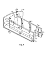
- Fig. 4 is a fragmentary isometric view of the plate-type liquid redistributor of Figs. 2 and 3.
- Fig. 5 is a side view of a segment of a
duct wall 40 ofdistributor 10 as seen from itsvapor side 42 showing the relationships between anorifice 46 in theduct wall 40 and its pair ofdrip rods 48 and thehorizontal plate 32, and anoverflow slot 50. - Fig. 6 is an alternative embodiment of that of Fig. 5 illustrating how pairs of
drip rods 48 can be offset from theirrespective openings 46 where the distance "A" is not equal to the distance "B". - Fig. 7 is an alternative embodiment of that of Fig. 5 showing the special relationship between pairs of
drip rods 48 to theirrespective openings 46 wherein one drip rod serves as a right side drip rod of a pair of drip rods for one opening but also serves as a left side drip rod of a pair of drip rods for an adjacent opening. This condition occurs only when the drip rods are spaced equidistant between theopening 46. Here again the distance "A" equals the distance "B". - Fig. 8 is a top view of a trough-type liquid distributing apparatus made according to this invention.
- Fig. 9 is a cross-sectional view of the trough-type distributing apparatus of Fig. 8 as seen along line 9-9 in Fig. 8.
- With particular reference to Fig. 1, three plate-
type liquid distributors exchange column tower 16. These threedistributors tower 16 and the liquid dripping downwardly intower 16 in a substantially uniformly distributed manner. The vapor flow is illustrated by wavey arrows while the dripping liquid is represented by the dotted lines shown below each distributor. Beneath eachdistributor Tower 16 is equipped with twoliquid feed lines vapor discharge line 30, and a vapor feed line 24. - Vapor is fed into the bottom of
tower 16 from heating means (not shown) via line 24 and rises upwardly, as indicated by the wavey arrows, throughcolumn packing bed 18,distributor 10,column packing bed 20, distributor 12,column packing bed 22,distributor 14, and out oftower 16 vialine 30.Liquid distributors 10 and 12 have liquid indiscriminately falling upon them fromcolumn packing beds distributors 10 and 12, this liquid is redistributed so that it falls in a substantially uniformly distributed manner across the top of thecolumn packing beds -
Distributors 12 and 14 also show how liquid such as reflux can be injected into them for distribution from outside sources vialines - In the event there is no liquid falling from above as is shown for
distributor 14, then the distributors do not need a covering means such asroofs 52, shown more clearly in Figs. 2, 3, and 4. - The
distributors tower 16 since leakage of liquid between thedistributors -
Distributor 10 is shown attached to tower 16 bybolts 31 and nuts 33. Other means of attachment such as welding could also be used. Thedistributor 10 has ahorizontal plate member 32 to which is sealingly attached avertical flange 34 extending around the periphery of theplate member 32.Flange 34 extends above theplate member 32 so as to form aliquid reservoir 36 within it and aboveplate member 32. -
Plate member 32 has two rectangularly shaped openings and two trapezoidally-shaped openings cut through it in this particular embodiment. Each of these four openings has aduct 38 installed in it. Theseducts 38 are defined byvertical duct walls 40 which are sealingly attached (as by welding) toplate member 32 such that the walls extend above and below theplate member 32. Theliquid reservoir 36, therefore, is more precisely defined as the space abovehorizontal plate 32, insideflange 34, and outside ofducts 38. - The shape of
ducts 38 is not important. For example, they could be circular or polyagonal in horizontal cross-sectional shape. What is important is that their total horizontal cross-sectional area be sufficient to allow passage of rising vapors through them without incurring significant pressure drops while at the same time providingenough ducts 38 withwalls 40 spaced close enough together to distribute liquid in a satisfactorily uniform manner across an imaginary horizontal plane located immediately beneathdistributor 10. - The inside of
wall 40, on which side vapor rises freely through theplate 32, is defined as thevapor side 42. A portion of the other side, or outside, ofduct walls 40 aboveplate 32 is in contact with the liquid contained inreservoir 36. This side ofduct wall 40, therefore, is defined as thereservoir side 44. The presence of liquid in and aroundducts 38 withinreservoir 36 is more clearly shown in Fig. 3. - Referring now to Figs. 4 and 5, a series of substantially uniformly spaced,
round orifices 46 of the same diameter extend through theduct walls 40. Theorifices 46 are spaced at an equal distance aboveplate 32. The purpose of theorifices 46 is to allow liquid to pass fromreservoir 36 throughduct walls 40 to thevapor side 42 of the duct walls where it can fall in a substantially uniformly distributed manner into the tower space belowdistributor 10. (Fig. 3). The orifices are not placed on the bottom of the reservoir as is usually the custom because it has been discovered that debris and sediment in the liquid tends to settle to the bottom of the reservoir to cause rapid plugging of such holes. Of course, plugging of any distribution holes causes an undesired maldistribution of the liquid. - Besides being round, having equal diameters, and being positioned at the same distance above
plate 32,orifices 46 are also spaced at substantially the same distance from each other. These criteria provide for a substantially uniform distribution of the liquid as it drains from the outlets oforifices 46 on thevapor side 42 ofduct wall 40. However, these criteria do not by themselves assure a uniform distribution of liquid from the bottom of the distributor. Additional features include the extension ofduct walls 40 belowhorizontal plate 32 along with the presence, proper location, and extension ofvertical drip rods 48 extending belowduct walls 40. These drip rods form an adherring surface to which liquid flowing from thesmall orifices 46 can adhere and thus flow directly downwardly by gravity. -
Drip rods 48 are attached vertically to thevapor side 42 ofduct walls 40 and preferably extend downwardly past the bottom ofduct walls 40. Furthermoredrip rods 48 are attached adjacent to each side of eachorifice 46. Thus, eachorifice 46 has a pair ofdrip rods 48 between which liquid can flow downwardly to the bottom tips of thedrip rods 48. Fromdrip rods 48, the liquid drips in a substantially uniformly distributed manner from the distributor. It has been discovered that liquid often adheres to the bottom surface ofplate 32 and tends to flow to the lowest part ofplate 32. There it drips off in a maldistributed manner. However, whenduct walls 40 extend below the bottom ofplate 32 and whendrip rods 48 are present and extend below the bottom ofduct walls 40, this maldistribution does not occur. - With particular reference to Figs. 5, 6 and 7, each opening 46 has a pair of
drip rods 48 associated with it, one of thedrip rods 48 of the pair being adjacent to the opening on one side and theother drip rod 48 of the pair being adjacent to the opening on the opposite side. The term "adjacent" is not used herein as merely meaning abutting, although abutting (i.e., tangent to) is included in the meaning of adjacent. Adjacent means nearby, or close to, or the one closest in a given direction. - In Fig. 5, there is shown a
preferred drip rod 48 to opening 46 configuration. The leftadjacent drip rod 48 is shown at a distance "A" from opening 46 while the rightadjacent drip rod 48 of the pair is shown at a distance "B" from theopening 46. In Fig. 5, the distance A is equal to the distance B, A = B and, moreover, A = B = one-half of the diameter, D, of the opening. The distance betwen thedrip rods 48 of any pair of drip rods is given as "Z". In all embodiments the distance "Z" of all pairs of drip rods is constant in that embodiment. This space between pairs of drip rods is defined above as the "equidistant channel" for theopening 46 associated with that pair ofdrip rods 48. - In Fig. 6, each pair of
drip rods 48 associated with anopening 46 is off-set from thatopening 46. Thus the distance "A" does not equal the distance "B". However, the distance "Z" is constant for each "equidistant channel". Also the distance "A" is constant for eachopening 40 as is the distance "B" for eachopening 40. - In Fig. 7, the same constancy of the distances "A", "B" and "Z" exist across the
duct wall 40. However, here thedrip rods 48 are placed equidistantly betweenopenings 46. That is, onedrip rod 48 not only serves as theright drip rod 48 for oneopening 46, but it also serves as theleft drip rod 48 for anotheropening 46 located to the right of the drip rod. Thus, a single drip rod is equidistantly positioned between a pair ofopenings 46. It will be understood, of course, that the drip rods may also be positioned in an off--centered relationship with respect to theopenings 46. - Other specific configurations of drip rod pairs will come to mind which fit the criteria stated above in the statement of invention section for the relationships between the drip rod pairs and their associated openings.
- Referring to Figs. 4 and 5, it will be noticed that
rectangular slots 50 are cut into the tops ofduct walls 40. Theslots 50 are overflow slots which are present for the purpose of providing uniformity of distribution when liquid is fed too fast into thereservoir 36 and thereservoir 36 overflows.Slots 50 . are preferably cut to the same depth in theduct wall 40 and each slot is partially offset from theparticular orifice 46 located below it. This offset is just enough so that onedrip rod 48 extends upwardly into theslot 50 so as to act as a guide for liquid overflowing fromreservoir 36 in much the same manner as it acts for liquid exiting fromorifice 46. - The
distributor 10 is provided with a covering means which will prevent liquid falling from a distributor from falling directly through theducts 38 ofdistributor 10, but yet will allow vapor rising through theducts 38 to pass on upwardly around this covering means and out ofdistributor 10 without incurring significant pressure drop while passing throughdistributor 10. An example of such covering means areroofs 52 mounted directly aboveducts 38. (See Figs. 2, and 3 in particular). These roofs are supported byvertical rods 54 at a sufficiently elevated position above the top ofduct walls 40 to allow the passage of rising vapors therebetween without incurring a significant pressure drop. Therods 54 are welded toduct walls 40 and theroofs 52 are secured to therods 54 bybolts 56 or the like.Roof 52 is a leak-proof flat plate which can be horizontally or angularly mounted so long as it prevents liquid from falling directly into and through theducts 38.Roofs 52 are not necessary when liquid is piped directly into thereservoir 36 and no liquid is falling on the distributor, as is shown withdistributor 14 in Fig. 1. - The method of operation of
distributor 10 is as follows. Liquid falling indiscriminately from.above distributor 10 (represented by dotted lines in Fig. 1), either falls directly intoreservoir 36 or falls on top ofroofs 52 from which it drains intoreservoir 36. - The level of the liquid in
reservoir 36 is maintained at a fairly constant level 57 (see Fig. 3) above theorifices 46 by sizing the orifices and controlling their number based on the flow rate of liquid normally expected to be flowing through the distributor. In case this flow rate is increased to the point of overflow, fromreservoir 36, this overflow is patterned into a substantially uniform distribution flow by the presence of thenotches 50 through which the overflow passes, and the presence of thedrip rods 48 located in their bottoms. The overflow liquid adheres to these drip rods and flows downwardly to the bottoms from which it drips. - Vapor rising from below
distributor 10 passes upwardly through theducts 38 and through the open space between the top ofducts 38 and the bottom ofroofs 52. - In a preferred embodiment, the
distributor 10 is cut into separate pieces so that it can be more easily passed through manways in a tower. - Another embodiment of the trough-type distributor of this invention is illustrated in Figs. 8 and 9.
Troughs 70 are generally box-like in shape. That is they have twovertical sides 71, a bottom 72, two closed ends 73, and an open top. Thetroughs 70 are horizontal and parallel to each other and are spaced from each other. Thetroughs 70 have theirends 73 shaped for fitting into a cylindrical tower. Liquid is fed totroughs 70 from a splitter box 74 via pairs ofsized holes 75 located in the bottom 80 of the splitter box 74. Theholes 75 are located above their respective troughs so that liquid will flow into the trough and not into thespaces 77 between thetroughs 70. Thespaces 77 are present to allow gas rising from beneath the distributor to pass through the distributor without incurring significant pressure drop. Theholes 75 are sized so that an amount of liquid which is proportional to the size of eachtrough 70 will flow into thedifferent length troughs 70. - The splitter box 74 has
sides 78, ends 79, and a bottom 80, and is generally open at its top. - In the
sides 71 oftroughs 70 are located a plurality ofround orifices 81 which are all located at the same horizontal elevation in all thetroughs 70 and which are also spaced from one another in a substantially uniform manner. The orifices are all of the same diameter and are sized small enough such that for the liquid they are designed to allow to pass from the inside oftrough 70 to its outside, the liquid level intrough 70 will be above the top of theround orifices 81; that is, theround orifices 81 will be submerged with respect to the liquid level in thetroughs 70. - Associated with each
orifice 81 is a pair of vertical, parallel,drip rods 82 which are attached to the outside oftroughs 70; that is, on the vapor side oftroughs 70 as described above for the plate-type distributor. Adrip rod 82 is located on and adjacent to each side of eachorifice 81. Thus when liquid emerges from the inside oftrough 70 through anorifice 81, it contacts the pair of drip rods to which it can adhere and flow downwardly into a channel formed between a pair ofparallel drip rods 82 associated with thatorifice 81. Thedrip rods 82 extend below the bottom of the trough for a better distribution pattern of the liquid. This distribution is brought about because the liquid will adhere to the drip rods and follow them down to their bottom ends before they fall instead of adhering to the bottom 72 oftrough 70 and running along it to some unknown collection site before dripping off. Liquid dripping from the bottoms of thedrip rods 82 provide a much more uniform flow distribution.
said duct walls having a plurality of openings spaced apart at a substantially uniform distance and located at the same distance above the plate to allow the liquid to accumulate in the reservoir and to pass out of the reservoir in streamlets through the openings in the duct walls while allowing sediment contained in the liquid to settle to the bottom of the reservoir, the tops of said openings being located below the tops of the duct walls as well as below the top of the upstanding flange so that a pool of liquid is capable of being maintained in said reservoir space with the upper surface of the liquid being situated above the tops of said openings, said openings being small enough in size so as to cause the liquid to form a pool in said reservoir with the upper surface of the liquid being maintained above the tops of said openings in order that any flotating debris in the liquid will remain above said openings
Claims (4)
Applications Claiming Priority (2)
| Application Number | Priority Date | Filing Date | Title |
|---|---|---|---|
| US06/469,077 US4432913A (en) | 1981-08-31 | 1983-02-23 | Liquid distributing apparatus and method for a liquid-vapor contact column |
| US469077 | 1983-02-23 |
Publications (2)
| Publication Number | Publication Date |
|---|---|
| EP0119643A2 true EP0119643A2 (en) | 1984-09-26 |
| EP0119643A3 EP0119643A3 (en) | 1985-01-23 |
Family
ID=23862331
Family Applications (1)
| Application Number | Title | Priority Date | Filing Date |
|---|---|---|---|
| EP84200188A Withdrawn EP0119643A3 (en) | 1983-02-23 | 1984-02-10 | Liquid distributing apparatus and method for a liquid-vapor contact column |
Country Status (5)
| Country | Link |
|---|---|
| US (1) | US4432913A (en) |
| EP (1) | EP0119643A3 (en) |
| JP (1) | JPS59162901A (en) |
| AU (1) | AU543776B2 (en) |
| BR (1) | BR8400862A (en) |
Cited By (4)
| Publication number | Priority date | Publication date | Assignee | Title |
|---|---|---|---|---|
| DE3907436A1 (en) * | 1988-03-22 | 1989-10-12 | Kuehni Ag | LIQUID DISTRIBUTOR FOR MATERIAL AND HEAT EXCHANGE COLONES |
| CN102614677A (en) * | 2012-04-24 | 2012-08-01 | 宜兴汉光高新石化有限公司 | Multi-layer rectification tower |
| CN108089443A (en) * | 2017-12-17 | 2018-05-29 | 北京世纪隆博科技有限责任公司 | A kind of sensitive plate temperature intelligent modeling method based on mixing elite stable breeding optimization |
| CN111560273A (en) * | 2020-03-11 | 2020-08-21 | 上海兖矿能源科技研发有限公司 | Chilling tower for separating Fischer-Tropsch synthesis products and process system thereof |
Families Citing this family (29)
| Publication number | Priority date | Publication date | Assignee | Title |
|---|---|---|---|---|
| US4472325A (en) * | 1983-06-13 | 1984-09-18 | The Dow Chemical Company | Liquid distributor apparatus for a vapor-liquid contact column |
| US4776989A (en) * | 1983-09-19 | 1988-10-11 | The Dow Chemical Company | Method and apparatus for liquid feed to liqiud distributors in fluid-liquid contacting towers |
| US4689183A (en) * | 1985-12-02 | 1987-08-25 | The Dow Chemical Company | Ultra low flow rate liquid redistributor assembly for use in a liquid-vapor contact tower |
| GB8903008D0 (en) * | 1989-02-10 | 1989-03-30 | Shell Int Research | Draw-off device |
| US5000883A (en) * | 1989-10-23 | 1991-03-19 | Max Leva | Apparatus and method for supporting packing in mass transfer towers and subsequent liquid redistribution |
| US5291533A (en) * | 1993-03-22 | 1994-03-01 | Westinghouse Electric Corp. | Cooling water distribution system |
| US5345482A (en) * | 1993-05-06 | 1994-09-06 | Westinghouse Electric Corporation | Passive containment cooling water distribution device |
| US5464573A (en) * | 1994-05-09 | 1995-11-07 | Koch Engineering Company, Inc. | Liquid collector-distributor with integral exchange column and method |
| DE4418488A1 (en) * | 1994-05-27 | 1995-11-30 | Basf Ag | Method and device for separating mixtures of substances by distillation |
| US6802941B2 (en) * | 2001-01-18 | 2004-10-12 | Ovation Products Corporation | Distiller employing cyclical evaporation-surface wetting |
| US7007932B2 (en) * | 2003-07-25 | 2006-03-07 | Air Products And Chemicals, Inc. | Wall-flow redistributor for packed columns |
| US8408026B2 (en) * | 2007-08-21 | 2013-04-02 | Air Products And Chemicals, Inc. | Liquid collector and redistributor for packed columns |
| US8205863B2 (en) * | 2008-06-03 | 2012-06-26 | Uop Llc | Distributor for a gas-liquid contacting vessel |
| US20100294645A1 (en) * | 2009-05-20 | 2010-11-25 | Zanaqua Technologies | Combined sump and inline heater for distillation system |
| CA2689266A1 (en) * | 2009-12-23 | 2011-06-23 | Aker Solutions Canada Inc. | Improved distributor |
| WO2012134470A1 (en) | 2011-03-31 | 2012-10-04 | Air Products And Chemicals, Inc. | Shielding in a separation column |
| JP6063269B2 (en) * | 2013-01-18 | 2017-01-18 | 株式会社クレハ | Redisperser for packed tower, packed tower and distillation method of vinylidene chloride monomer |
| FR3006599B1 (en) | 2013-06-10 | 2015-05-29 | IFP Energies Nouvelles | DISPENSER PLATE FOR GAS / LIQUID CONTACT COLUMN WITH SECONDARY DISTRIBUTION SYSTEM |
| FR3016533B1 (en) | 2014-01-21 | 2016-01-15 | IFP Energies Nouvelles | DISPENSER PLATE FOR EXCHANGE COLUMN BETWEEN GAS AND LIQUID WITH LIQUID DEFLECTOR |
| DE102014105008B4 (en) * | 2014-04-08 | 2017-05-18 | Technische Universität Berlin | Liquid distributor and arrangement |
| FR3030309B1 (en) | 2014-12-19 | 2016-12-23 | Ifp Energies Now | DISPENSING TRAY FOR HEAT EXCHANGE COLUMN AND / OR MATERIAL COMPRISING BULLAGE MEANS |
| JP7079559B2 (en) * | 2015-04-28 | 2022-06-02 | 住友重機械エンバイロメント株式会社 | Dehydrator |
| US20180318727A1 (en) | 2015-10-30 | 2018-11-08 | Total Sa | Column for heat and/or mass exchange between two fluids comprising a collection tray and fluid separation means |
| BR112018008201A2 (en) | 2015-10-30 | 2018-10-23 | Total Sa | heat and / or matter exchange column between two fluids comprising a manifold and gas mixing means |
| JP6178454B1 (en) * | 2016-03-28 | 2017-08-09 | 大陽日酸株式会社 | Packed tower |
| FR3060405B1 (en) | 2016-12-19 | 2021-07-09 | Ifp Energies Now | MATERIAL AND / OR HEAT EXCHANGE COLUMN BETWEEN A GAS AND A LIQUID WITH LIQUID RECIRCULATION MEANS |
| FR3067946A1 (en) | 2017-06-23 | 2018-12-28 | IFP Energies Nouvelles | DISPENSER TRAY FOR EXCHANGE COLUMN WITH HOUSING FOR GAS DISTRIBUTION |
| FR3100320B1 (en) * | 2019-09-02 | 2022-02-18 | Air Liquide | Distribution device for a gas/liquid separation column |
| JP7108659B2 (en) * | 2020-06-02 | 2022-07-28 | 住友重機械エンバイロメント株式会社 | Dehydrator |
Citations (7)
| Publication number | Priority date | Publication date | Assignee | Title |
|---|---|---|---|---|
| DE219458C (en) * | 1909-06-15 | 1910-03-07 | ||
| DE1151491B (en) * | 1960-01-11 | 1963-07-18 | Union Oil Co | Device for the uniform distribution of a liquid-vapor mixture on a contact bed of solid particles |
| DE1542543A1 (en) * | 1965-12-20 | 1970-08-13 | Norton Co | Liquid distributor for reaction towers |
| DE2251800A1 (en) * | 1972-10-21 | 1974-05-02 | Koppers Gmbh Heinrich | GAS- AND LIQUID-PERMEABLE DISTRIBUTION BOTTOM FOR TOWER-LIKE CONTACT DEVICES |
| DE2752391A1 (en) * | 1977-11-24 | 1979-05-31 | Montz Gmbh Julius | Trickling column distributor plate - with serrated edges for channel overflow and for guide plate dripping |
| DE2945103A1 (en) * | 1979-11-08 | 1981-05-21 | Julius Montz Gmbh, 4010 Hilden | Counterflow column fluid distributor - with perforations and run=off tongues on parallel side walls of channels |
| DE3118836A1 (en) * | 1980-05-14 | 1982-02-18 | Norton Co., 01606 Worcester, Mass. | LIQUID DISTRIBUTOR FOR FUEL BODY COLUMNS |
Family Cites Families (14)
| Publication number | Priority date | Publication date | Assignee | Title |
|---|---|---|---|---|
| US632795A (en) * | 1899-05-06 | 1899-09-12 | Frederick Wallis Stoddart | Distributer for liquids. |
| US1673732A (en) * | 1926-08-19 | 1928-06-12 | Frank E Gunter | Cooling device |
| US2590779A (en) * | 1948-11-12 | 1952-03-25 | Utility Appliance Corp | Water distributing apparatus for evaporative coolers |
| US3006623A (en) * | 1958-12-29 | 1961-10-31 | Exxon Research Engineering Co | Fluid distributor for packed columns |
| US3446489A (en) * | 1965-07-08 | 1969-05-27 | Max Leva | Liquid distributors and redistributors for contact towers |
| US3290025A (en) * | 1965-11-19 | 1966-12-06 | Baltimore Aircoil Co Inc | Trough system for evaporative heat exchangers |
| US3392967A (en) * | 1965-12-20 | 1968-07-16 | Us Stoneware Inc | Trough-type distributor |
| US3360246A (en) * | 1966-02-25 | 1967-12-26 | Us Stoneware Inc | Distributor with bed-level limiter |
| CH534532A (en) * | 1970-12-31 | 1973-03-15 | Sulzer Ag | Liquid distributor for a mass transfer column |
| US3723072A (en) * | 1971-03-12 | 1973-03-27 | Universal Oil Prod Co | Fluid contacting apparatus |
| US4126540A (en) * | 1973-08-03 | 1978-11-21 | Atlantic Richfield Company | Apparatus and process for distributing a mixed phase through solids |
| US3937769A (en) * | 1973-12-27 | 1976-02-10 | Norton Company | Liquid distributor |
| SU573176A1 (en) * | 1974-05-30 | 1977-09-25 | Предприятие П/Я Г-4236 | Liquid distributor for mass-exchange apparatus |
| CA1120396A (en) * | 1979-01-09 | 1982-03-23 | Rolf P.C. Manteufel | Device for feeding liquids into material and heat exchanger columns |
-
1983
- 1983-02-23 US US06/469,077 patent/US4432913A/en not_active Expired - Lifetime
-
1984
- 1984-02-01 AU AU23957/84A patent/AU543776B2/en not_active Ceased
- 1984-02-10 EP EP84200188A patent/EP0119643A3/en not_active Withdrawn
- 1984-02-22 BR BR8400862A patent/BR8400862A/en unknown
- 1984-02-23 JP JP59031550A patent/JPS59162901A/en active Granted
Patent Citations (7)
| Publication number | Priority date | Publication date | Assignee | Title |
|---|---|---|---|---|
| DE219458C (en) * | 1909-06-15 | 1910-03-07 | ||
| DE1151491B (en) * | 1960-01-11 | 1963-07-18 | Union Oil Co | Device for the uniform distribution of a liquid-vapor mixture on a contact bed of solid particles |
| DE1542543A1 (en) * | 1965-12-20 | 1970-08-13 | Norton Co | Liquid distributor for reaction towers |
| DE2251800A1 (en) * | 1972-10-21 | 1974-05-02 | Koppers Gmbh Heinrich | GAS- AND LIQUID-PERMEABLE DISTRIBUTION BOTTOM FOR TOWER-LIKE CONTACT DEVICES |
| DE2752391A1 (en) * | 1977-11-24 | 1979-05-31 | Montz Gmbh Julius | Trickling column distributor plate - with serrated edges for channel overflow and for guide plate dripping |
| DE2945103A1 (en) * | 1979-11-08 | 1981-05-21 | Julius Montz Gmbh, 4010 Hilden | Counterflow column fluid distributor - with perforations and run=off tongues on parallel side walls of channels |
| DE3118836A1 (en) * | 1980-05-14 | 1982-02-18 | Norton Co., 01606 Worcester, Mass. | LIQUID DISTRIBUTOR FOR FUEL BODY COLUMNS |
Cited By (6)
| Publication number | Priority date | Publication date | Assignee | Title |
|---|---|---|---|---|
| DE3907436A1 (en) * | 1988-03-22 | 1989-10-12 | Kuehni Ag | LIQUID DISTRIBUTOR FOR MATERIAL AND HEAT EXCHANGE COLONES |
| DE3907436C2 (en) * | 1988-03-22 | 2000-12-28 | Kuehni Ag Allschwil | Liquid distributor for mass and heat exchange columns |
| CN102614677A (en) * | 2012-04-24 | 2012-08-01 | 宜兴汉光高新石化有限公司 | Multi-layer rectification tower |
| CN108089443A (en) * | 2017-12-17 | 2018-05-29 | 北京世纪隆博科技有限责任公司 | A kind of sensitive plate temperature intelligent modeling method based on mixing elite stable breeding optimization |
| CN111560273A (en) * | 2020-03-11 | 2020-08-21 | 上海兖矿能源科技研发有限公司 | Chilling tower for separating Fischer-Tropsch synthesis products and process system thereof |
| CN111560273B (en) * | 2020-03-11 | 2021-07-13 | 上海兖矿能源科技研发有限公司 | Chilling tower for separating Fischer-Tropsch synthesis products and process system thereof |
Also Published As
| Publication number | Publication date |
|---|---|
| JPS6123001B2 (en) | 1986-06-04 |
| AU2395784A (en) | 1984-09-13 |
| US4432913A (en) | 1984-02-21 |
| JPS59162901A (en) | 1984-09-13 |
| EP0119643A3 (en) | 1985-01-23 |
| BR8400862A (en) | 1984-10-02 |
| AU543776B2 (en) | 1985-05-02 |
Similar Documents
| Publication | Publication Date | Title |
|---|---|---|
| US4432913A (en) | Liquid distributing apparatus and method for a liquid-vapor contact column | |
| US4476069A (en) | Liquid distributing apparatus for a liquid-vapor contact column | |
| US4689183A (en) | Ultra low flow rate liquid redistributor assembly for use in a liquid-vapor contact tower | |
| EP0737498B1 (en) | Gas-liquid contacting tray with side discharging triangular downcomers | |
| US4909967A (en) | Liquid distributor assembly for packed tower | |
| US5051214A (en) | Double-deck distributor and method of liquid distribution | |
| US4729857A (en) | Liquid distributor for packed tower | |
| US4264538A (en) | Liquid distributor | |
| US4472325A (en) | Liquid distributor apparatus for a vapor-liquid contact column | |
| US5061407A (en) | Liquid distributor for gas-liquid contact apparatus | |
| US5707563A (en) | V-module fractionation tray | |
| US9956500B2 (en) | Liquid mixing collector and a method for its use | |
| US2646977A (en) | Vapor liquid contact apparatus | |
| EP1316345B3 (en) | Liquid distributor with internal baffling | |
| US2428922A (en) | Liquid distributing apparatus | |
| US6830607B2 (en) | Slurry tray and slurry tray assembly for use in fractionation towers | |
| US8205863B2 (en) | Distributor for a gas-liquid contacting vessel | |
| EP0378408B1 (en) | Double-deck distributor | |
| EP0367525A1 (en) | Liquid distributor assembly for packed tower | |
| EP0169611B1 (en) | Column and process for gas/liquid contact | |
| JP2009508684A (en) | Apparatus and method for dispensing two liquids that are immiscible with each other | |
| JPH086499Y2 (en) | Liquid disperser | |
| EP3995195A1 (en) | A multistage liquid distributor for a separation device comprising a dual-trough pre-distributor | |
| JPH1119401A (en) | Liquid catching and distributing device | |
| SU1003877A2 (en) | Apparatus for distributing phases |
Legal Events
| Date | Code | Title | Description |
|---|---|---|---|
| PUAI | Public reference made under article 153(3) epc to a published international application that has entered the european phase |
Free format text: ORIGINAL CODE: 0009012 |
|
| AK | Designated contracting states |
Designated state(s): BE CH DE FR GB IT LI NL |
|
| PUAL | Search report despatched |
Free format text: ORIGINAL CODE: 0009013 |
|
| AK | Designated contracting states |
Designated state(s): BE CH DE FR GB IT LI NL |
|
| RHK1 | Main classification (correction) |
Ipc: B01D 3/00 |
|
| 17P | Request for examination filed |
Effective date: 19850722 |
|
| 17Q | First examination report despatched |
Effective date: 19860317 |
|
| STAA | Information on the status of an ep patent application or granted ep patent |
Free format text: STATUS: THE APPLICATION IS DEEMED TO BE WITHDRAWN |
|
| 18D | Application deemed to be withdrawn |
Effective date: 19870321 |
|
| RIN1 | Information on inventor provided before grant (corrected) |
Inventor name: HARPER, STEPHEN MARK Inventor name: STULTZ, JEFFREY HIRAM |