EP0119595A2 - Fluorinated graphites, a process for their production and an electric cell using the same as active material of the positive electrode - Google Patents
Fluorinated graphites, a process for their production and an electric cell using the same as active material of the positive electrode Download PDFInfo
- Publication number
- EP0119595A2 EP0119595A2 EP84102806A EP84102806A EP0119595A2 EP 0119595 A2 EP0119595 A2 EP 0119595A2 EP 84102806 A EP84102806 A EP 84102806A EP 84102806 A EP84102806 A EP 84102806A EP 0119595 A2 EP0119595 A2 EP 0119595A2
- Authority
- EP
- European Patent Office
- Prior art keywords
- electric cell
- fluorinated graphite
- active material
- positive electrode
- graphite
- Prior art date
- Legal status (The legal status is an assumption and is not a legal conclusion. Google has not performed a legal analysis and makes no representation as to the accuracy of the status listed.)
- Granted
Links
Images



Classifications
-
- H—ELECTRICITY
- H01—ELECTRIC ELEMENTS
- H01M—PROCESSES OR MEANS, e.g. BATTERIES, FOR THE DIRECT CONVERSION OF CHEMICAL ENERGY INTO ELECTRICAL ENERGY
- H01M4/00—Electrodes
- H01M4/02—Electrodes composed of, or comprising, active material
- H01M4/36—Selection of substances as active materials, active masses, active liquids
- H01M4/58—Selection of substances as active materials, active masses, active liquids of inorganic compounds other than oxides or hydroxides, e.g. sulfides, selenides, tellurides, halogenides or LiCoFy; of polyanionic structures, e.g. phosphates, silicates or borates
- H01M4/583—Carbonaceous material, e.g. graphite-intercalation compounds or CFx
-
- C—CHEMISTRY; METALLURGY
- C01—INORGANIC CHEMISTRY
- C01B—NON-METALLIC ELEMENTS; COMPOUNDS THEREOF; METALLOIDS OR COMPOUNDS THEREOF NOT COVERED BY SUBCLASS C01C
- C01B32/00—Carbon; Compounds thereof
- C01B32/10—Carbon fluorides, e.g. [CF]nor [C2F]n
-
- H—ELECTRICITY
- H01—ELECTRIC ELEMENTS
- H01M—PROCESSES OR MEANS, e.g. BATTERIES, FOR THE DIRECT CONVERSION OF CHEMICAL ENERGY INTO ELECTRICAL ENERGY
- H01M4/00—Electrodes
- H01M4/02—Electrodes composed of, or comprising, active material
- H01M4/36—Selection of substances as active materials, active masses, active liquids
- H01M4/58—Selection of substances as active materials, active masses, active liquids of inorganic compounds other than oxides or hydroxides, e.g. sulfides, selenides, tellurides, halogenides or LiCoFy; of polyanionic structures, e.g. phosphates, silicates or borates
- H01M4/583—Carbonaceous material, e.g. graphite-intercalation compounds or CFx
- H01M4/5835—Comprising fluorine or fluoride salts
-
- H—ELECTRICITY
- H01—ELECTRIC ELEMENTS
- H01M—PROCESSES OR MEANS, e.g. BATTERIES, FOR THE DIRECT CONVERSION OF CHEMICAL ENERGY INTO ELECTRICAL ENERGY
- H01M6/00—Primary cells; Manufacture thereof
- H01M6/14—Cells with non-aqueous electrolyte
- H01M6/16—Cells with non-aqueous electrolyte with organic electrolyte
Definitions
- the present invention relates to a novel fluorinated graphite, a process for the production of the same and an electric cell comprising the same as an active material of the positive electrode.
- fluorinated graphites there are known polymeric fluorinated graphites having the formula of (CF) n [hereinafter referred to “(CF) "] and those having the formula (C 2 F) n [hereinafter referred to “(C 2 F) n “] which are produced by allowing fluorine gas to react with a graphite material in a vessel maintained at a temperature of 350°C to 600°C (U.S. Patent 4,139,474 to Watanabe et al.). It is also known that electric cells using such fluorinated graphites as an active material of a positive electrode in combination with alkali metals such as lithium as a negative electrode exhibit a high discharge voltage, a flat characteristic of the discharge curve and an excellent shelf life.
- fluorinated graphites having the formula of (C X F) n wherein x is a numerical value of 3.6 to 4.0 can be produced by allowing a mixed gas of fluorine and hydrogen fluoride to react with a carbon material [Chem. Ber., vol. 80, page 413 (1947)].
- a mixed gas of fluorine and hydrogen fluoride to react with a carbon material [Chem. Ber., vol. 80, page 413 (1947)].
- excessive fluorine gas must be employed and also high temperatures are required. Since such high temperatures as above are near the dissociation temperature of the C-F bond, great efforts must be made to obtain the products at high yields.
- the corrosion of the reaction vessel is large, and thus it may be said that these processes are disadvantageous for a poduction of fluorinated graphites in an industrial scale.
- active materials for a positive electrode of an electric cell of high performance are required to have a high electromotive force, a high open circuit voltage and, in addition, a small overvoltage on discharge, a good flat characteristic of the dischage curve and a large discharge capacity per unit weight per se when they are used in combination with an appropriate negative electrode. Furthermore, the active materials are required to be neither decomposed nor dissolved in the electrolyte of an electric cell and have to be stable for a long period of time.
- the positive electrode active material containing fluorine which is an element having the highest positive standard potential among all the elements can provide a small-sized, light-weight electric cell having a high voltage and a high energy density in combination with an appropriate negative electrode.
- the active materials for the positive electrode of such an electric cell which have been widely studied include fluorides of copper, nickel, silver, etc., (CF) and (C 2 F) n .
- the copper fluoride and the nickel fluoride have a high theoretical energy density and exhibit an open circuit voltage as high as at least 3V when used together with lithium metal as a negative electrode, but disadvantageously they are unstable in the electrolyte and the self-discharge is so remarkable that the discharge capacity is greatly decreased in a few days.
- (CF) n and (C2F) n are excellent active materials for a positive electrode which provide an open circuit voltage as high as 3.2V and an excellent uniformity of discharge voltage and are stable in an electrolyte for a long period of time in combination with lithium metal as a negative electrode.
- (CF) n the overvoltage on discharge is large, and a large potential drop at a high load discharge can be observed.
- the present inventors have therefore made extensive studies to develop an industrially advantageous process for producing fluorinated graphites avoiding the defects of the conventional techniques. As a result, the inventors have found that this purpose can be accomplished by electrolytically fluorinating a carbon material in hydrogen fluoride and that the fluorinated graphite thus produced is a novel substance and exhibits novel discharge characteristics when used as an active material for a positive electrode of an electric cell.
- the present invention relates to a fluorinated graphite having the formula (C x F) n wherein x is a numerical value of about 2.0 to about 5.5 and n refers to an indefinite number of the recurring (C x F) unit and having a crystalline structure exhibiting a peak at about 13.7 0 to about 15.0° in terms of an angle of 28 corresponding to the diffraction at the (001) plane in the X-ray diffraction pattern, a peak in the vicinity of 685.3 eV due to the F 1S and two peaks in the vicinity of 287.5 eV and 284.3 eV due to the C 1S in the spectrum of electron spectroscopy of chemical analysis (hereinafter referred to "ESCA"), two peaks in the vicinity of 1100 cm -1 and 1240 cm -1 in the IR spectrum, an electric conductivity of at least about 10 -8 ⁇ -1 cm -1 and being thermally stable in air up to 200 o C from the viewpoint concerning the X-ray dif
- the present invention also relates to a process for producing a fluorinated graphite as described above which comprises subjecting a carbon material to electrolysis in hydrogen fluoride at a voltage of about 6.5V to about 15V at a temperature of about -40°C to about 100°C in the presence of an electically conductive agent.
- the present invention further relates to an electric cell which comprises a negative electrode using a light metal as an active material, an electrolyte and a positive electrode using, as an active material, the above described fluorinated graphite.
- the present invention still further relates to an electric cell which comprises a negative electrode having a light metal as an active material, an electrolyte and a positive electrode having, as an active material, the fluorinated graphite treated with an alkali or potassium iodide.
- Exemplary carbon materials which can be employed in the present invention are easily graphitizable carbons and include petroleum coke, pitch, meso-phase pitch, calcined vinyl chloride, carbon whisker, graphite obtained by heat treatment thereof and natural graphite.
- meso-phase pitch, heat-treated meso-phase pitch and natural graphite are preferred, and heat-treated meso-phase pitch is more preferred.
- the shape of the carbon material may be in the form of powder, flakes, granules, whiskers, fibers or sheets, and the carbon materials maybe employed in layers or in bundles, and the size of these layers or bundles is not limited as long as their width is smaller than the effective electrode area.
- the thickness or the diameter of a sheet or a fiber is preferably at most about 5 mm, more preferably at most 2 mm. Any amount of the carbon materials may be employed if they are provided within the effective electrode area.
- the apparatus for producing the fluorinated graphite of the present invention may be typically made of copper, nickel, silver, stainless steel or any combination thereof and may have an anode and a cathode made of nickel, stainless steel or copper.
- the electrodes may be in the form of plates, nets or cocentric cylinders. It is preferred to employ cylindrical electrodes which have the following advantages:
- the cylindrical electrodes which can be preferably employed in the present invention are formed by a combination of two cylinders which are cocentrically placed and whose distance is uniform.
- the cylinders may not be necessarily circular and one electrode encircles the other electrode at a substantially equal distance.
- the cylinders may be porous or netlike, and part of the cylinders may be missing or the inner-positioned cylinder may be replaced by a rod.
- the electrolytic fluorination according to the present invention proceeds at the anode. Accordingly, it is preferred that the carbon material be disposed on the anode or in the vicinity of the anode. As an exemplary method, the carbon material is uniformly spread on the anode and fixed with a net of polytetrafluoroethylene. In an electrolytic vessel there are charged the carbon material and hydrogen fluoride containing an electrically conductive agent, and electric power is applied under the prescribed conditions.
- the electrolytic temperature employed is typically about -40°C to about 100°C, preferably about -30°C to 20°C.
- the electrolytic temperature is lower than about -40°C, the velocity of electrolytic fluorination becomes lower which is unfavourable from the industrial view-point.
- the temperature is higher than 100°C, the pressure of hydrogen fluoride is increased, and hence this is inconvenient from the view-point of operating the electrolysis.
- the voltage applied is typically about 6.5V to about 15V, preferably about 7V to about 10V.
- the voltage is lower than about 6.5V, the electric current density is decreased, and accordingly a long reaction time will be required for the electrolysis.
- the voltage is higher than 15V, the operation of the electrolysis becomes dangerous, because of the extensive generation of fluorine gas.
- the electrolytic fluorination of the present invention is conducted in an atmosphere of dried air, for example, treated with a dehydrating agent such as calcium chloride, potassium hydroxide and sulfuric acid, or in an inert gas such as nitrogen, argon and helium.
- a dehydrating agent such as calcium chloride, potassium hydroxide and sulfuric acid
- an inert gas such as nitrogen, argon and helium.
- Exemplary electrically conductive agents which can be employed in the present invention include water and metal salts.
- water it is preferred that the weight ratio of water to hydrogen fluoride be kept in the range of about 0.0001 to about 0.01.
- the weight ratio of water to hydrogen fluoride is less than about 0.0001, the electrical conductivity becomes smaller and the current density is reduced and as a result, the electrolysis requires a long period of time.
- the efficiency of fluorination is decreased and the properties of an electric cell containing the fluorinated graphite produced are adversely affected.
- Exemplary metal salts which can be employed as the electrically conductive agent in the present invention include metal fluorides such as sodium fluoride, potassium fluoride, calcium fluoride and magnesium fluoride.
- the amount of the metal fluorides employed is preferably in the range of about 1 % by weight to about 20 % by weight based on the weight of the hydrogen fluoride.
- the quantity of electricity applied is typically in the range of about 2 x 10 3 coulombs to about 1 x 10 6 coulombs per gram of the carbon material.
- the fluorination reaction proceeds very rapidly, and compounds having a composition of a certain range of a ratio of carbon to fluorine can be produced in a very short period of time.
- the gloss of the product formed is slightly lost externally but the color and the shape of the starting carbon material are maintained in the products.
- the weight of the products shows an increase of about 30 % to about 80 % over that of the starting carbon material.
- the elementary analysis and the spectral analysis show that the product is a fluorinated carbon compound consisting of covalent bonds.
- the fluorinated graphite of the present invention has a composition of (C x F) n wherein x is about 2.0 to about 5.5 and n refers to an indefinite number of the recurring (C F) unit.
- x is about 2.0 to about 5.5
- n refers to an indefinite number of the recurring (C F) unit.
- a peak can be observed in the range of about 13.7° to about 15.0° in terms of an angle of 2 ⁇ corresponding to the diffraction at the (001) plane. This corresponds to an interlayer spacing of about 6.46A to about 5.90A.
- FIG. 1 shows a representative example of the X-ray diffraction pattern of the fluorinated graphite of the present invention.
- n is a numerical value of about 2.0 to about 4.0 and n refers to an indefinite number of the recurring (C x F) unit and a crystalline structure exhibiting a peak at about 13.7° to about 14.8° in terms of an angle of 28 corresponding to the diffraction at the (001) plane in the X-ray diffraction pattern.
- the fluorinated graphite of the present invention has an electric conductivity of at least about 1 x 10 -8 (ohm.cm) -1 and a thermal stability, i.e., no structural change occurring up to 200°C in air from the viewpoint concerning a X-ray diffraction pattern, and no weight loss being observed up to 400°C in a nitrogen atmosphere by the thermogravimetric analysis.
- the IR spectrum of the fluorinated graphite of the present invention shows two absorptions characteristic for the stretching vibration of the F-C bond in the vicinity of 1100 cm -1 and 1240 cm -1 and its pattern is different from the absorptions of the conventional fluorinated graphite.
- FIG. 2 shows a representative IR spectrum of the fluorinated graphite of the present invention, and the intensity ratio of the peak in the vicinity of 1100 cm-l to the peak in the vicinity of 1240 cm 1 varies depending upon the electrolysis conditions and the fluorination ratio.
- the fluorinated graphite of the present invention is treated with an alkali or potassium iodide and is employed as an active material for the positive electrode of a cell, the shelf life of the cell can be remarkably prolonged and the flatness of discharge curve can be markedly improved.
- the alkalis which can be employed in the present invention may be any conventional alkali reagents and include, for example, sodium hydroxide, potassium hydroxide, an aqueous ammonia solution, aliphatic primary amines such as propylamine and butylamine, aliphatic secondary amines such as isopropylamine and isoamylamine, aliphatic tertiary amines such as t-butylamine and t-amylamine, aromatic primary amines such as aniline and benzylamine, aromatic secondary amines such as N-methylbenzylamine and N-ethylbenzylamine, aromatic tertiary amines such as benzyldiethylamine and heterocyclic amines such as pyridine and pyridazine.
- sodium hydroxide is especially preferred.
- the alkali be employed as the aqueous solution having a concentration of the alkali of about 0.5 % by weight to about 5 % by weight.
- concentration of the alkali of less than about 0.5 % by weight the effect for treating the fluorinated graphite with the alkali cannot be exhibited satisfactorily.
- concentration of the alkali of more than about 5 % by weight there can be disadvantageously and unnecessarily caused a diffusion of fluorine into the solution potassium iodide is employed, it is preferred to employ an aqueous solution of potassium iodide of about 0.01N to about 0.1N.
- the treatment can be carried out by charging the flourinated graphite of the present invention in the aqueous solution of the alkali or potassium iodide and stirring the mixture at room temperature (in the range of about 15°C to about 35 0 C) for a period in the range of about 5 minutes to about 2 hours and then subjecting it to filtration.
- the fluorinated graphite thus separated is thoroughly washed with water and dried in vacuum.
- the positive electrode in the electric cell of the present invention may be prepared as follows.
- the fine powder of the fluorinated graphite of the present invention is thoroughly mixed with a binder such as powder or granule of polyethylene, a fluoropolymer such as polytetrafluoroethylene, a S B R resin and an expanded graphite, if necessary or if desired, together with an electrically conductive agent such as carbon powder and acetylene black in order to increase a short-circuit current.
- the mixture obtained is molded into a predetermined shape to form a positive electrode.
- the amount of the binder employed is typically in the range of about 1 % by weight to about 20 % by weight based on the weight of an active material.
- the active materials of a negative electrode of a cell which can be employed in the present invention are light metals or light metal alloys and include alkali metals such as lithium, sodium and potassium, alkaline earth metals such as calcium and magnesium, aluminum, any mixtures thereof, and alloys containing any of these metals as a main component.
- alkali metals such as lithium, sodium and potassium
- alkaline earth metals such as calcium and magnesium, aluminum, any mixtures thereof, and alloys containing any of these metals as a main component.
- the alkali metals which have a low negative electrode potential are preferred, and lithium is more preferred.
- the electrolyte which can be employed in the electric cell of the present invention depends upon a negative electrode metal employed and may be either of an aprotic organic solvent system or a protonic solvent system.
- aprotic organic solvents for the electrolyte include Y -butyrolactone, propylene carbonate, ethylene carbonate, dimethylformamide, dimethyl sulfoxide, tetrahydrofuran, dimethyl sulfite, 1,2-dimethoxyethane, methyl formate and acetonitrile.
- Exemplary protonic solvents for the electrolyte include water, ethylene glycol, glycerin, monochloroacetic acid and dichloroacetic acid. The concentration of the electrolyte is not critical and may be chosen so as to give a high electrical conductivity.
- the solute of the electrolyte which can be employed in the present invention include various compounds such as LiClO 4 , LiBF 4 , KPF6, LiAlCl 4 and any mixtures thereof.
- the electric cell of the present invention exhibits, as its characteric feature, an open circuit voltage of about 3.6V to about 4.0V and a discharge voltage at a constant resistance of 2.6KQ of about 3.3V which are higher than those of the conventional electric cell using, for example, (CF)n and (C 2 F) n , respectively, as an active material for a positive electrode and, in addition, is excellent in uniformity of discharge voltage and exhibits a utility of about 100 % and good stability for a long period of time.
- the term "utility" means the ratio of the experimental discharge capacity to the theoretical capacity calculated from the amount of the active material for the negative electrode.
- the electric cell of the present invention is advantageously used in devices requiring a high voltage such as a watch, a clock, a small radio and a small computer.
- the electrolytic vessel employed was a cylinder made of copper-nickel alloy having an internal volume of 660 ml equipped with a reflux condenser.
- An anode and a cathode employed as electrodes were both nickel plates having a thickness of 0.5 mm and the electrode distance was 0.5 cm and their effective area was 76 cm 2 .
- On the anode 1.0 g of pitch type graphite monofilaments having a diameter of 10 ⁇ m whose X-ray spacing was 3.36 ⁇ and a length of 5 cm (trade mark "Thornel P-55S" manufactured by Union Carbide Corporation, U.S.A.) was uniformly spread and fixed with a polytetrafluoroethylene thread.
- the electrolytic vessel was charged 650 ml of hydrofluoric acid containing 1 ml of water, and the electrolysis was conducted in an argon atmosphere for 8 hours under the conditions that the average current density was 1.5A/cm , the voltage applied was 8V and the bath temperature was -20°C.
- the 100 ml of hydrofluoric acid containing 1 ml of water was additionally charged into the electrolytic vessel and the electrolysis was conducted further for 16 hours under the same conditions as described above.
- the total quantity of electricity applied was 13 x 10 coulomb per gram of the carbon monofilaments.
- the color of the product obtained was maintained black, and the volume of the monofilaments was increased to give the monofilaments having a diameter of 14 ⁇ m and the increase in weight was 56 %.
- the contents of fluorine and carbon were 36 % by weight and 64 % by weight, respectively, which corresponded to a composition of (C 2.8 F) n ⁇
- a peak was observed at 14.5°(28) as shown FIG. 1 and the peak of the starting carbon material at 26.5°(2 ⁇ ) corresponding to the diffraction at the (002) plane was not observed, and the conversion of the carbon material was 100 %.
- the product had an interlayer spacing of 6.10 ⁇ , and exhibited one peak at 1100 cm -1 and another peak at 1200 cm -1 in the I R spectrum, one peak at 685.1 eV due to the F 1S and two peaks at 287.5 eV and 284.3 eV due to the C 1S in the ESCA spectrum, and was stable up to 200°C in air from the viewpoint of a X-ray diffraction pattern and did not show weight loss up to 400°C in a nitrogen atmosphere.
- the color of the product was black and the electric conductivity was 0.5 ⁇ 1 cm -1 .
- Example 2 The procedures of Example 1 were repeated except that the electrolytic voltage was 9V, the average current density was 2.5A/dm 2 and the total quantity of electricity applied was 21.6 x 10 4 coulomb.
- the product obtained was increased in weight by 64 %.
- the elementary analysis showed that the product had a composition of (C 2.5 F) n . According to the X-ray diffraction pattern, a sharp peak was observed at 14.4°(2 ⁇ ), and the conversion of the starting carbon material was 100 %.
- the product had an interlayer spacing of 6.15A, and exhibited one peak at 1080 cm -1 and another peak at 1220 cm -1 in the I R spectrum, one peak at 685.3 eV due to the F 1s and two peaks at 287.4 eV and 284.1 eV due to the C 1S in the ESCA spectrum, and did not change up to 200°C in air from the viewpoint of X-ray diffraction pattern.
- the temperature at which weight loss in a nitrogen atmosphere started was 400°C
- the color of the product was black and the electric conductivity was 10 -2 ⁇ -1 cm -1 .
- Example 2 The procedures of Example 1 were repeated except that 0.5 g of a sheet having a thickness of 0.2 mm having been molded from a mixture of graphitized petroleum coke and 10 % by weight of polytetrafluoroethylene powder was sticked on the anode as a carbon material and fixed with a polytetrafluoroethylene fiber. The increase in weight of the product was 69 %. The elementary analysis showed that the product had a composition of (C 2.3 F) n . According to the X-ray diffraction pattern, a peak was observed at 14.3 0 (28), and the conversion of the starting carbon material was 100 %.
- the product exhibited one peak at 1080 cm -1 and another peak at 1230 cm -1 in the IR spectrum, one peak at 685.5 eV due to the F 1S and two peaks at 287.5 eV and 284.5 eV due to the C 1S in the ESCA spectrum.
- the product was stable in air up to 200°C from the viewpoint of X-ray diffraction pattern.
- the initial temperature of thermally losing weight in air was 400°C
- the color of the product was black and electric conductivity was 10 -3 ⁇ -1 cm -1 .
- Example 1 The procedures of Example 1 were repeated except that graphatized whiskers obtained by the heat treatment of benzene at high temperatures having a diameter of 5 ⁇ m and a length of 1 to 5 cm were employed. The relationship between the total quantity of electricity applied and the product obtained is shown in Table 1.
- the product obtained had a composition of (C 3.0 F) n and according to the X-ray diffraction pattern, it had a peak at 14.6°(2 ⁇ ) and the conversion of the starting carbon material was 100 %.
- the product exhibited one peak at 1100 cm 1 and another peak at 1220 cm -1 in the IR spectrum and one peak at 685.1 eV due to the F 1S and two peaks at 287.8 eV and 284.6 eV due to the C 1S in the ESCA spectrum.
- the electric conductivity of was 3.0 ⁇ cm -1 .
- Example 11 The procedures of Example 11 were repeated except that various carbon materials as set forth in Table 2 were employed and that the total quantity of electricity applied was 7.7 x 10 4 coulomb/g. The results are shown in Table 2.
- Example 11 The procedures of Example 11 were repeated except that the electrolytic temperature was varied as set forth in Table 3 and that the amount of the carbon material used was 1.0 g. The results are shown in Table 3 .
- Example 2 The procedures of Example 1 were repeated except that 15 g of sodium fluoride were employed as an electrically conductive agent instead of water.
- the product obtained showed an increase in weight by 50 %. According to the X-ray diffraction pattern, a peak was observed at 14.7 0 (26), and the conversion of the starting carbon material was 100 %.
- the product had an interlayer spacing of 6.03 ⁇ and was thermally stable in air up to 200°C and had an electric conductivity of 8 ⁇ -1 cm -1 .
- Example 2 The procedures of Example 1 were repeated except that 10 g of potassium fluoride were employed as an electrically conductive agent instead of water.
- the product obtained showed an increase in weight by 50 % by weight.
- the product obtained had a composition of (C4.2F)n.
- a peak was observed at 15.0 0 (28), and the conversion of the sarting carbon material was 100 %.
- the product had an interlayer spacing of 5.90A and was thermally stable in air up to 200°C and had an electric conductivity of 15 ⁇ -1 cm -1 .
- Example 7 To 0.15 g of the fluorinated graphite having a composition of (C 3.3 F) n as obtained in Example 7 was added 0.03 g of polytetrafluoroethylene powder and thoroughly mixed. The mixture was press-molded into a disc having a diameter of 15 mm and a thickness of 0.6 mm for using as a positive electrode. As a negative electrode was employed a disc sheet having a diameter of . 15 mm and a thickness of 0.20 mm. A button cell as shown in FIG. 3 was prepared. As shown in FIG.
- the electric cell comprised a stainless steel container 3 to the bottom of which a positive-electrode disc 5 was adhered with an electrically conductive adhesive, a stainless steel inverted cup 1 inside which the negative-electrode disc 2 of lithium was press-adhered and a separator 4 of a polypropylene unwoven fabric which was disposed between the positive electrode disc 5 and the negative electrode disc 2.
- a y-butyrolactone solution containing 1 mol/liter of LiBF 4 was charged in the container 3 as an electolyte
- the container 1 was sealed within the open end of the container 3 by means of a plastic insulating gasket 6.
- the inverted cup 1 and the container 3 acted as the negative electrode terminal and the positive electrode terminal, respectively.
- the open circuit voltage at 25 0 C of the electric cell thus prepared was 3.9V which was higher than that of 3.2V of the electric cell employing (CF) as an active material for a positive electrode.
- the electric cell had an excellent flatness of discharge curve at constant-resistance of 3.3K and maintained an average voltage of 3.3V which was a very high value compared to 2.65V of the electric cell employing (CF) as an active material for a positive electrode, as shown in FIG. 4.
- the fibers as obtained by the elctrolytic fluorination in Example 13 were finely and sufficiently pulverized in a mortar, and 1 g of the fluorinated graphite thus obtained each as a sample was immersed in 10 ml of a 1 % by weight aqueous sodium hydroxide solution, 10 ml of a 2 % by weight aqueous ammonia solution, 10 ml of a 0.5 % by weight aqueous pyridine solution and 10 ml of a 0.05N aqueous potassium iodide solution, respectively, and the mixtures thus obtained were stirred at 25°C for 30 minutes.
- the aqueous potassium iodide solution the mixture was stirred in a dark place at 25°C for 30 minutes and then was left to stand in the dark place at 5°C for one hour.
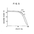
- FIG. 5 shows discharge curves of the electric cells at 25°C at a constant-resistance of 2.6 K ⁇ immediately after their preparation.
- A, B, C and D show the discharge curves of the electric cells employing the fluorinated graphites having been treated with the 1 % by weight aqueous sodium hydroxide solution, the 2 % by weight aqueous ammonia solution, the 0.5 % by weight aqueous pyridine solution and the 0.05N aqueous potassium iodide solution, respectively, as an active material for the positive electrode.
- E shows the discharge curve of the electric cell employing the untreated fluorinated graphite as an active material for the positive electrode.
- FIG. 6 shows discharge curves of the same five electric cells described above at 25°C at a constant-resistance of 2.6 K ⁇ after their storage at 60°C for one month.
- Example 23 In the same manner as in Example 23, two button cells were prepared using the fluorinated graphite as obtained in Example 13 as an active material for the positive electrode and sodium or magnesium as the negative electrode.
- the discharge characteristics of the electric cells are shown in Table 4.
Landscapes
- Chemical & Material Sciences (AREA)
- Inorganic Chemistry (AREA)
- General Chemical & Material Sciences (AREA)
- Chemical Kinetics & Catalysis (AREA)
- Electrochemistry (AREA)
- Organic Chemistry (AREA)
- Engineering & Computer Science (AREA)
- Life Sciences & Earth Sciences (AREA)
- Environmental & Geological Engineering (AREA)
- General Life Sciences & Earth Sciences (AREA)
- Geology (AREA)
- Manufacturing & Machinery (AREA)
- Battery Electrode And Active Subsutance (AREA)
- Secondary Cells (AREA)
- Carbon And Carbon Compounds (AREA)
Abstract
Description
- The present invention relates to a novel fluorinated graphite, a process for the production of the same and an electric cell comprising the same as an active material of the positive electrode.
- As fluorinated graphites there are known polymeric fluorinated graphites having the formula of (CF)n [hereinafter referred to "(CF) "] and those having the formula (C2F)n [hereinafter referred to "(C2F)n"] which are produced by allowing fluorine gas to react with a graphite material in a vessel maintained at a temperature of 350°C to 600°C (U.S. Patent 4,139,474 to Watanabe et al.). It is also known that electric cells using such fluorinated graphites as an active material of a positive electrode in combination with alkali metals such as lithium as a negative electrode exhibit a high discharge voltage, a flat characteristic of the discharge curve and an excellent shelf life. (U.S. Patents 3,536,532, 3,700,502 and 4,247,608). Further, it is disclosed that fluorinated graphites having the formula of (CXF)n wherein x is a numerical value of 3.6 to 4.0 can be produced by allowing a mixed gas of fluorine and hydrogen fluoride to react with a carbon material [Chem. Ber., vol. 80, page 413 (1947)]. In the production of these fluorinated graphites, however, excessive fluorine gas must be employed and also high temperatures are required. Since such high temperatures as above are near the dissociation temperature of the C-F bond, great efforts must be made to obtain the products at high yields. Moreover, under such conditions the corrosion of the reaction vessel is large, and thus it may be said that these processes are disadvantageous for a poduction of fluorinated graphites in an industrial scale.
- On the other hand, active materials for a positive electrode of an electric cell of high performance are required to have a high electromotive force, a high open circuit voltage and, in addition, a small overvoltage on discharge, a good flat characteristic of the dischage curve and a large discharge capacity per unit weight per se when they are used in combination with an appropriate negative electrode. Furthermore, the active materials are required to be neither decomposed nor dissolved in the electrolyte of an electric cell and have to be stable for a long period of time.
- It is considered that the positive electrode active material containing fluorine which is an element having the highest positive standard potential among all the elements can provide a small-sized, light-weight electric cell having a high voltage and a high energy density in combination with an appropriate negative electrode. The active materials for the positive electrode of such an electric cell which have been widely studied include fluorides of copper, nickel, silver, etc., (CF) and (C2F)n. The copper fluoride and the nickel fluoride have a high theoretical energy density and exhibit an open circuit voltage as high as at least 3V when used together with lithium metal as a negative electrode, but disadvantageously they are unstable in the electrolyte and the self-discharge is so remarkable that the discharge capacity is greatly decreased in a few days. Further, the overvoltage on discharge is large and the uniformity of discharge voltage is poor. Thus, the cells using the copper fluoride and the nickel fluoride as the active material for a positive electrode have not yet been of practical use. On the other hand, (CF)n and (C2F)n are excellent active materials for a positive electrode which provide an open circuit voltage as high as 3.2V and an excellent uniformity of discharge voltage and are stable in an electrolyte for a long period of time in combination with lithium metal as a negative electrode. However, with (CF) nthe overvoltage on discharge is large, and a large potential drop at a high load discharge can be observed. With (C2F)n the overvoltage on discharge is smaller than that of (CF) , and (C2F)n is accordingly more useful, but the time for recovering the open circuit voltage after a high load discharge is long. Thus, optimum active materials for a positive electrode are still desired.
- The present inventors have therefore made extensive studies to develop an industrially advantageous process for producing fluorinated graphites avoiding the defects of the conventional techniques. As a result, the inventors have found that this purpose can be accomplished by electrolytically fluorinating a carbon material in hydrogen fluoride and that the fluorinated graphite thus produced is a novel substance and exhibits novel discharge characteristics when used as an active material for a positive electrode of an electric cell.
-
- FIG. 1 shows the X-ray diffraction pattern of a typical fluorinated graphite in Example 1 of the present invention;
- FIG. 2 shows the IR spectrum of a typical fluorinated graphite in Example 10 of the present invention;
- FIG. 3 is a cross-sectional view of a typical button cell of the present invention;
- FIG. 4 is a curve showing a discharge characteristic of a button electric cell using a typical fluorinated graphite in Example 7 of the present invention as an active material for a positive electrode;
- FIG. 5 is a group of curves showing discharge characteristics of the cells using the fluorinated graphite treated with a variety of alkalis or potassium iodide or the untreated fluorinated graphite of Example 24 of the present invention as a positive electrode active material immediately after their preparation; and
- FIG. 6 is a group of curves showing discharge characteristics of the same electric cells of Example 24 of the present invention after their storage at 60°C for one month.
- The present invention relates to a fluorinated graphite having the formula (CxF)n wherein x is a numerical value of about 2.0 to about 5.5 and n refers to an indefinite number of the recurring (CxF) unit and having a crystalline structure exhibiting a peak at about 13.70 to about 15.0° in terms of an angle of 28 corresponding to the diffraction at the (001) plane in the X-ray diffraction pattern, a peak in the vicinity of 685.3 eV due to the F1S and two peaks in the vicinity of 287.5 eV and 284.3 eV due to the C1S in the spectrum of electron spectroscopy of chemical analysis (hereinafter referred to "ESCA"), two peaks in the vicinity of 1100 cm-1 and 1240 cm-1 in the IR spectrum, an electric conductivity of at least about 10-8Ω-1cm-1 and being thermally stable in air up to 200oC from the viewpoint concerning the X-ray diffraction pattern.
- The present invention also relates to a process for producing a fluorinated graphite as described above which comprises subjecting a carbon material to electrolysis in hydrogen fluoride at a voltage of about 6.5V to about 15V at a temperature of about -40°C to about 100°C in the presence of an electically conductive agent.
- The present invention further relates to an electric cell which comprises a negative electrode using a light metal as an active material, an electrolyte and a positive electrode using, as an active material, the above described fluorinated graphite.
- The present invention still further relates to an electric cell which comprises a negative electrode having a light metal as an active material, an electrolyte and a positive electrode having, as an active material, the fluorinated graphite treated with an alkali or potassium iodide.
- Exemplary carbon materials which can be employed in the present invention are easily graphitizable carbons and include petroleum coke, pitch, meso-phase pitch, calcined vinyl chloride, carbon whisker, graphite obtained by heat treatment thereof and natural graphite. Among these carbon materials, meso-phase pitch, heat-treated meso-phase pitch and natural graphite are preferred, and heat-treated meso-phase pitch is more preferred.
- The shape of the carbon material may be in the form of powder, flakes, granules, whiskers, fibers or sheets, and the carbon materials maybe employed in layers or in bundles, and the size of these layers or bundles is not limited as long as their width is smaller than the effective electrode area. In order to increase the rate of reaction, the thickness or the diameter of a sheet or a fiber is preferably at most about 5 mm, more preferably at most 2 mm. Any amount of the carbon materials may be employed if they are provided within the effective electrode area.
- The apparatus for producing the fluorinated graphite of the present invention may be typically made of copper, nickel, silver, stainless steel or any combination thereof and may have an anode and a cathode made of nickel, stainless steel or copper. The electrodes may be in the form of plates, nets or cocentric cylinders. It is preferred to employ cylindrical electrodes which have the following advantages:
- (a) The fluorination of the carbon material proceeds rapidly and uniformly and thus the current efficiency can be improved, and the time period of the electrolysis can be shortened.
- (b) The batchwise amount of the carbon material can be increased.
- (c) The discharge characteristics of an electric cell using a fluorinated graphite as an active material of the positive elecrode can be improved.
- The cylindrical electrodes which can be preferably employed in the present invention are formed by a combination of two cylinders which are cocentrically placed and whose distance is uniform. The cylinders may not be necessarily circular and one electrode encircles the other electrode at a substantially equal distance. The cylinders may be porous or netlike, and part of the cylinders may be missing or the inner-positioned cylinder may be replaced by a rod.
- The electrolytic fluorination according to the present invention proceeds at the anode. Accordingly, it is preferred that the carbon material be disposed on the anode or in the vicinity of the anode. As an exemplary method, the carbon material is uniformly spread on the anode and fixed with a net of polytetrafluoroethylene. In an electrolytic vessel there are charged the carbon material and hydrogen fluoride containing an electrically conductive agent, and electric power is applied under the prescribed conditions.
- The electrolytic temperature employed is typically about -40°C to about 100°C, preferably about -30°C to 20°C. When the electrolytic temperature is lower than about -40°C, the velocity of electrolytic fluorination becomes lower which is unfavourable from the industrial view-point. On the other hand, when the temperature is higher than 100°C, the pressure of hydrogen fluoride is increased, and hence this is inconvenient from the view-point of operating the electrolysis. The voltage applied is typically about 6.5V to about 15V, preferably about 7V to about 10V. When the voltage is lower than about 6.5V, the electric current density is decreased, and accordingly a long reaction time will be required for the electrolysis. On the other hand, when the voltage is higher than 15V, the operation of the electrolysis becomes dangerous, because of the extensive generation of fluorine gas.
- The electrolytic fluorination of the present invention is conducted in an atmosphere of dried air, for example, treated with a dehydrating agent such as calcium chloride, potassium hydroxide and sulfuric acid, or in an inert gas such as nitrogen, argon and helium.
- Exemplary electrically conductive agents which can be employed in the present invention include water and metal salts. When water is employed, it is preferred that the weight ratio of water to hydrogen fluoride be kept in the range of about 0.0001 to about 0.01. When the weight ratio of water to hydrogen fluoride is less than about 0.0001, the electrical conductivity becomes smaller and the current density is reduced and as a result, the electrolysis requires a long period of time. On the other hand, at weight ratios of water to hydrogen fluoride of more than about 0.01, the efficiency of fluorination is decreased and the properties of an electric cell containing the fluorinated graphite produced are adversely affected.
- Exemplary metal salts which can be employed as the electrically conductive agent in the present invention include metal fluorides such as sodium fluoride, potassium fluoride, calcium fluoride and magnesium fluoride. In order to maintain an appropriate electrical conductivity and to prevent excess corrosion of the electrodes, the amount of the metal fluorides employed is preferably in the range of about 1 % by weight to about 20 % by weight based on the weight of the hydrogen fluoride.
- In the production of the fluorinated graphite of the present invention the quantity of electricity applied is typically in the range of about 2 x 10³ coulombs to about 1 x 10⁶ coulombs per gram of the carbon material. The fluorination reaction proceeds very rapidly, and compounds having a composition of a certain range of a ratio of carbon to fluorine can be produced in a very short period of time.
- The gloss of the product formed is slightly lost externally but the color and the shape of the starting carbon material are maintained in the products. Generally, the weight of the products shows an increase of about 30 % to about 80 % over that of the starting carbon material. The elementary analysis and the spectral analysis show that the product is a fluorinated carbon compound consisting of covalent bonds.
- According to the elementary analysis the fluorinated graphite of the present invention has a composition of (CxF)n wherein x is about 2.0 to about 5.5 and n refers to an indefinite number of the recurring (C F) unit. According to the X-ray diffraction pattern a peak can be observed in the range of about 13.7° to about 15.0° in terms of an angle of 2θ corresponding to the diffraction at the (001) plane. This corresponds to an interlayer spacing of about 6.46A to about 5.90A. FIG. 1 shows a representative example of the X-ray diffraction pattern of the fluorinated graphite of the present invention. It is preferred from the viewpoint of an active material for a positive electrode of an electric cell to employ the fluorinated graphite having a chemical composition of the formula (CxF)n wherein x is a numerical value of about 2.0 to about 4.0 and n refers to an indefinite number of the recurring (CxF) unit and a crystalline structure exhibiting a peak at about 13.7° to about 14.8° in terms of an angle of 28 corresponding to the diffraction at the (001) plane in the X-ray diffraction pattern. According to the ESCA spectrum of the fluorinated graphite of the present invention, a peak can be observed in the vicinity of 685.3 eV due to the F1S and two peaks in the vicinity of 287.5 eV and 284.3 eV due to the C1S. The fluorinated graphite of the present invention has an electric conductivity of at least about 1 x 10⁻⁸(ohm.cm)-1 and a thermal stability, i.e., no structural change occurring up to 200°C in air from the viewpoint concerning a X-ray diffraction pattern, and no weight loss being observed up to 400°C in a nitrogen atmosphere by the thermogravimetric analysis. The IR spectrum of the fluorinated graphite of the present invention shows two absorptions characteristic for the stretching vibration of the F-C bond in the vicinity of 1100 cm-1 and 1240 cm-1 and its pattern is different from the absorptions of the conventional fluorinated graphite. FIG. 2 shows a representative IR spectrum of the fluorinated graphite of the present invention, and the intensity ratio of the peak in the vicinity of 1100 cm-l to the peak in the vicinity of 1240 cm 1 varies depending upon the electrolysis conditions and the fluorination ratio.
- Furthermore, when the fluorinated graphite of the present invention is treated with an alkali or potassium iodide and is employed as an active material for the positive electrode of a cell, the shelf life of the cell can be remarkably prolonged and the flatness of discharge curve can be markedly improved.
- The alkalis which can be employed in the present invention may be any conventional alkali reagents and include, for example, sodium hydroxide, potassium hydroxide, an aqueous ammonia solution, aliphatic primary amines such as propylamine and butylamine, aliphatic secondary amines such as isopropylamine and isoamylamine, aliphatic tertiary amines such as t-butylamine and t-amylamine, aromatic primary amines such as aniline and benzylamine, aromatic secondary amines such as N-methylbenzylamine and N-ethylbenzylamine, aromatic tertiary amines such as benzyldiethylamine and heterocyclic amines such as pyridine and pyridazine. Among these alkalis, sodium hydroxide is especially preferred.
- It is preferred that the alkali be employed as the aqueous solution having a concentration of the alkali of about 0.5 % by weight to about 5 % by weight. In case of a concentration of the alkali of less than about 0.5 % by weight, the effect for treating the fluorinated graphite with the alkali cannot be exhibited satisfactorily. On the other hand, in case of a concentration of the alkali of more than about 5 % by weight, there can be disadvantageously and unnecessarily caused a diffusion of fluorine into the solution potassium iodide is employed, it is preferred to employ an aqueous solution of potassium iodide of about 0.01N to about 0.1N. In case of using an aqueous solution of potassium iodide less than about 0.01N, the effect for treating the fluorinated graphite therewith cannot satisfactorily exhibited. On the other hand, in case of using an aqueous solution of potassium iodide more than about O.lN, the diffusion of fluorine into the solution can be disadvantageously caused. Among these aqueous solutions of the alkalis and potassium iodide it is preferred to employ an aqueous solution of sodium hydroxide having a concentration of about 0.5 % by weight to about 5 % by weight.
- The treatment can be carried out by charging the flourinated graphite of the present invention in the aqueous solution of the alkali or potassium iodide and stirring the mixture at room temperature (in the range of about 15°C to about 350C) for a period in the range of about 5 minutes to about 2 hours and then subjecting it to filtration. The fluorinated graphite thus separated is thoroughly washed with water and dried in vacuum.
- The positive electrode in the electric cell of the present invention may be prepared as follows. The fine powder of the fluorinated graphite of the present invention is thoroughly mixed with a binder such as powder or granule of polyethylene, a fluoropolymer such as polytetrafluoroethylene, a SBR resin and an expanded graphite, if necessary or if desired, together with an electrically conductive agent such as carbon powder and acetylene black in order to increase a short-circuit current. The mixture obtained is molded into a predetermined shape to form a positive electrode. The amount of the binder employed is typically in the range of about 1 % by weight to about 20 % by weight based on the weight of an active material. In case of the amount of the binder employed of less than 1 % by weight, the binding effect cannot satisfactorily be exhibited. On the other hand, in case of the amount of more than 20 % by weight, a volume fraction of an active material is decreased, and thus a decrease of a capacity of an electric cell is disadvantageously caused.
- The active materials of a negative electrode of a cell which can be employed in the present invention are light metals or light metal alloys and include alkali metals such as lithium, sodium and potassium, alkaline earth metals such as calcium and magnesium, aluminum, any mixtures thereof, and alloys containing any of these metals as a main component. Among these metals, the alkali metals which have a low negative electrode potential are preferred, and lithium is more preferred.
- The electrolyte which can be employed in the electric cell of the present invention depends upon a negative electrode metal employed and may be either of an aprotic organic solvent system or a protonic solvent system. Exemplary aprotic organic solvents for the electrolyte include Y-butyrolactone, propylene carbonate, ethylene carbonate, dimethylformamide, dimethyl sulfoxide, tetrahydrofuran, dimethyl sulfite, 1,2-dimethoxyethane, methyl formate and acetonitrile. Exemplary protonic solvents for the electrolyte include water, ethylene glycol, glycerin, monochloroacetic acid and dichloroacetic acid. The concentration of the electrolyte is not critical and may be chosen so as to give a high electrical conductivity.
- The solute of the electrolyte which can be employed in the present invention include various compounds such as LiCℓO4, LiBF4, KPF6, LiAℓCℓ4 and any mixtures thereof.
- In combination with lithium as an active material for a negative electrode, the electric cell of the present invention exhibits, as its characteric feature, an open circuit voltage of about 3.6V to about 4.0V and a discharge voltage at a constant resistance of 2.6KQ of about 3.3V which are higher than those of the conventional electric cell using, for example, (CF)n and (C2F)n, respectively, as an active material for a positive electrode and, in addition, is excellent in uniformity of discharge voltage and exhibits a utility of about 100 % and good stability for a long period of time. In this connection, the term "utility" means the ratio of the experimental discharge capacity to the theoretical capacity calculated from the amount of the active material for the negative electrode. Thus, the electric cell of the present invention is advantageously used in devices requiring a high voltage such as a watch, a clock, a small radio and a small computer.
- The present invention is hereunder described in greater detail by reference to working examples, to which the scope of the present invention is by no means limited.
- The electrolytic vessel employed was a cylinder made of copper-nickel alloy having an internal volume of 660 ml equipped with a reflux condenser. An anode and a cathode employed as electrodes were both nickel plates having a thickness of 0.5 mm and the electrode distance was 0.5 cm and their effective area was 76 cm2. On the anode 1.0 g of pitch type graphite monofilaments having a diameter of 10 µm whose X-ray spacing was 3.36Å and a length of 5 cm (trade mark "Thornel P-55S" manufactured by Union Carbide Corporation, U.S.A.) was uniformly spread and fixed with a polytetrafluoroethylene thread.
- In the electrolytic vessel was charged 650 ml of hydrofluoric acid containing 1 ml of water, and the electrolysis was conducted in an argon atmosphere for 8 hours under the conditions that the average current density was 1.5A/cm , the voltage applied was 8V and the bath temperature was -20°C. The 100 ml of hydrofluoric acid containing 1 ml of water was additionally charged into the electrolytic vessel and the electrolysis was conducted further for 16 hours under the same conditions as described above. The total quantity of electricity applied was 13 x 10 coulomb per gram of the carbon monofilaments.
- The color of the product obtained was maintained black, and the volume of the monofilaments was increased to give the monofilaments having a diameter of 14 µm and the increase in weight was 56 %. According to the elementary analysis, the contents of fluorine and carbon were 36 % by weight and 64 % by weight, respectively, which corresponded to a composition of (C2.8F)n· According to the X-ray diffraction pattern, a peak was observed at 14.5°(28) as shown FIG. 1 and the peak of the starting carbon material at 26.5°(2θ) corresponding to the diffraction at the (002) plane was not observed, and the conversion of the carbon material was 100 %. The product had an interlayer spacing of 6.10Å, and exhibited one peak at 1100 cm-1 and another peak at 1200 cm-1 in the IR spectrum, one peak at 685.1 eV due to the F1S and two peaks at 287.5 eV and 284.3 eV due to the C1S in the ESCA spectrum, and was stable up to 200°C in air from the viewpoint of a X-ray diffraction pattern and did not show weight loss up to 400°C in a nitrogen atmosphere. The color of the product was black and the electric conductivity was 0.5Ω 1cm -1.
- The procedures of Example 1 were repeated except that the electrolytic voltage was 9V, the average current density was 2.5A/dm2 and the total quantity of electricity applied was 21.6 x 10⁴ coulomb. The product obtained was increased in weight by 64 %. The elementary analysis showed that the product had a composition of (C2.5F)n. According to the X-ray diffraction pattern, a sharp peak was observed at 14.4°(2θ), and the conversion of the starting carbon material was 100 %. The product had an interlayer spacing of 6.15A, and exhibited one peak at 1080 cm-1 and another peak at 1220 cm-1 in the IR spectrum, one peak at 685.3 eV due to the F1s and two peaks at 287.4 eV and 284.1 eV due to the C1S in the ESCA spectrum, and did not change up to 200°C in air from the viewpoint of X-ray diffraction pattern. The temperature at which weight loss in a nitrogen atmosphere started was 400°C, the color of the product was black and the electric conductivity was 10-2Ω-1cm-1.
- The procedures of Example 1 were repeated except that 0.5 g of a sheet having a thickness of 0.2 mm having been molded from a mixture of graphitized petroleum coke and 10 % by weight of polytetrafluoroethylene powder was sticked on the anode as a carbon material and fixed with a polytetrafluoroethylene fiber. The increase in weight of the product was 69 %. The elementary analysis showed that the product had a composition of (C2.3F)n. According to the X-ray diffraction pattern, a peak was observed at 14.30(28), and the conversion of the starting carbon material was 100 %. The product exhibited one peak at 1080 cm-1 and another peak at 1230 cm-1 in the IR spectrum, one peak at 685.5 eV due to the F1S and two peaks at 287.5 eV and 284.5 eV due to the C1S in the ESCA spectrum. The product was stable in air up to 200°C from the viewpoint of X-ray diffraction pattern. The initial temperature of thermally losing weight in air was 400°C, the color of the product was black and electric conductivity was 10-3Ω-1cm-1.
- The procedures of Example 1 were repeated except that graphatized whiskers obtained by the heat treatment of benzene at high temperatures having a diameter of 5 µm and a length of 1 to 5 cm were employed. The relationship between the total quantity of electricity applied and the product obtained is shown in Table 1.

- All the products were black in color and had an electric conductivity of 10-7Ω-1cm-1 (Example 10) to 25-1Ω-1cm-1 (Example 4), which shows the relationship that the electric conductivity was higher with a smaller extent of fluorination. Also they were thermally stable in air up to 200°C and showed two absorptions characteristic of the stretching vibration of F-C bond, i.e., one peak in the vicinity of 1100 cm-1 and another peak in the vicinity of 1240 cm-1 in the IR spectra, and one peak in the vicinity of 685.3 eV due to the F1S and two peaks in the vicinity of 287.5 eV and 284.3 eV due to the Cls. FIG. 2 illustrates the IR spectrum of the product obtained in Example 10.
- Around a cylinder made of nickel having a diameter of 3 cm was uniformly wound 0.8 g of pitch type carbon fibers having been heat-treated at 2700°C for 10 minutes, which was used as an anode. Outside of the anode was placed a cylinder made of nickel as a cathode at an electrode distance of 5 mm. The assembly thus formed was immersed in hydrofluoric acid containing 0.1 % by weight of water, and the electrolysis was conducted at -20°C at a constant voltage of 8V for 4 hours. The total quantity of electricity applied was 8.2 x 10⁴ coulomb. According to the elementary analysis, the product obtained had a composition of (C3.0F)n and according to the X-ray diffraction pattern, it had a peak at 14.6°(2θ) and the conversion of the starting carbon material was 100 %. The product exhibited one peak at 1100 cm 1 and another peak at 1220 cm-1 in the IR spectrum and one peak at 685.1 eV due to the F1S and two peaks at 287.8 eV and 284.6 eV due to the C1S in the ESCA spectrum. The electric conductivity of was 3.0Ω cm-1.
- The procedures of Example 11 were repeated except that various carbon materials as set forth in Table 2 were employed and that the total quantity of electricity applied was 7.7 x 10⁴ coulomb/g. The results are shown in Table 2.

- All the products exhibited one peak in the vicinity of 1100 cm-1 and another peak in the vicinity of 1240 cm-1 in the IR spectrum and one peak in the vicinity of 685.3 eV due to the F1S and two peaks in the vicinity of 287.5 eV and 284.3 eV due to the C1S in the ESCA spectrum.
- The procedures of Example 11 were repeated except that the electrolytic temperature was varied as set forth in Table 3 and that the amount of the carbon material used was 1.0 g. The results are shown in Table 3.

- As is clearly understood from Table 3, the property of the products is hardly affected by the electrolytic temperature. All the products had an electric conductivity of around 5Ω-1cm-1 and excellent thermal stability.
- The procedures of Example 1 were repeated except that 15 g of sodium fluoride were employed as an electrically conductive agent instead of water. The product obtained showed an increase in weight by 50 %. According to the X-ray diffraction pattern, a peak was observed at 14.70(26), and the conversion of the starting carbon material was 100 %. The product had an interlayer spacing of 6.03Å and was thermally stable in air up to 200°C and had an electric conductivity of 8Ω-1cm-1.
- The procedures of Example 1 were repeated except that 10 g of potassium fluoride were employed as an electrically conductive agent instead of water. The product obtained showed an increase in weight by 50 % by weight. According to the elementary analysis, the product obtained had a composition of (C4.2F)n. According to the X-ray diffraction pattern, a peak was observed at 15.00(28), and the conversion of the sarting carbon material was 100 %. The product had an interlayer spacing of 5.90A and was thermally stable in air up to 200°C and had an electric conductivity of 15Ω-1cm-1.
- To 0.15 g of the fluorinated graphite having a composition of (C3.3F)n as obtained in Example 7 was added 0.03 g of polytetrafluoroethylene powder and thoroughly mixed. The mixture was press-molded into a disc having a diameter of 15 mm and a thickness of 0.6 mm for using as a positive electrode. As a negative electrode was employed a disc sheet having a diameter of . 15 mm and a thickness of 0.20 mm. A button cell as shown in FIG. 3 was prepared. As shown in FIG. 3, the electric cell comprised a stainless steel container 3 to the bottom of which a positive-
electrode disc 5 was adhered with an electrically conductive adhesive, a stainless steel inverted cup 1 inside which the negative-electrode disc 2 of lithium was press-adhered and aseparator 4 of a polypropylene unwoven fabric which was disposed between thepositive electrode disc 5 and thenegative electrode disc 2. After a y-butyrolactone solution containing 1 mol/liter of LiBF4 was charged in the container 3 as an electolyte, the container 1 was sealed within the open end of the container 3 by means of a plastic insulatinggasket 6. The inverted cup 1 and the container 3 acted as the negative electrode terminal and the positive electrode terminal, respectively. - The open circuit voltage at 250C of the electric cell thus prepared was 3.9V which was higher than that of 3.2V of the electric cell employing (CF) as an active material for a positive electrode. The electric cell had an excellent flatness of discharge curve at constant-resistance of 3.3K and maintained an average voltage of 3.3V which was a very high value compared to 2.65V of the electric cell employing (CF) as an active material for a positive electrode, as shown in FIG. 4.
- The fibers as obtained by the elctrolytic fluorination in Example 13 were finely and sufficiently pulverized in a mortar, and 1 g of the fluorinated graphite thus obtained each as a sample was immersed in 10 ml of a 1 % by weight aqueous sodium hydroxide solution, 10 ml of a 2 % by weight aqueous ammonia solution, 10 ml of a 0.5 % by weight aqueous pyridine solution and 10 ml of a 0.05N aqueous potassium iodide solution, respectively, and the mixtures thus obtained were stirred at 25°C for 30 minutes. In the case of the aqueous potassium iodide solution used, the mixture was stirred in a dark place at 25°C for 30 minutes and then was left to stand in the dark place at 5°C for one hour.
- The samples immersed, respectively, in the aqueous sodium hydroxide solution, the aqueous ammonia solution and the aqueous pyridine solution were filtered off and sufficiently washed with ion-exchanged water until the filtrate became neutral, and then dried under vacuum. Similarly, the sample treated with potassium iodide was filtered off and sufficiently washed until potassium iodide was completely removed, and then dried under vacuum.
- One gram of each kind of the four active materials for the positive electrode as obtained above and one untreated active material for the positive electrode which was the same fluorinated graphite as obtained in Example 13, respectively, were mixed with 0.2 g of polytetrafluoroethylene powder, and the mixtures were thoroughly kneaded and press-molded to give a disc having a diameter of 16 mm and a thickness of 1 mm, resulting in five kinds of the positive electrodes of electric cells. In the same manner as in Example 23, five button cells were prepared using the positive electrode as obtained above.
- FIG. 5 shows discharge curves of the electric cells at 25°C at a constant-resistance of 2.6 KΩ immediately after their preparation. In FIG. 5, A, B, C and D show the discharge curves of the electric cells employing the fluorinated graphites having been treated with the 1 % by weight aqueous sodium hydroxide solution, the 2 % by weight aqueous ammonia solution, the 0.5 % by weight aqueous pyridine solution and the 0.05N aqueous potassium iodide solution, respectively, as an active material for the positive electrode. For comparison, E shows the discharge curve of the electric cell employing the untreated fluorinated graphite as an active material for the positive electrode.
- FIG. 6 shows discharge curves of the same five electric cells described above at 25°C at a constant-resistance of 2.6 KΩ after their storage at 60°C for one month.
- It is clearly understood from FIG. 6 that the discharge characteristics and the shelf life can be remarkably improved by using the fluorinated graphites of the present invention treated with sodium hydroxide, ammonia, pyridine and potassium iodide, respectively, as an active material for the positive electrode of an electric cell.
- In the same manner as in Example 23, two button cells were prepared using the fluorinated graphite as obtained in Example 13 as an active material for the positive electrode and sodium or magnesium as the negative electrode. The discharge characteristics of the electric cells are shown in Table 4.

- These electric cells had a very high discharge voltage and a good flatness of discharge curve and the utility was about 100 %.
Claims (29)
Applications Claiming Priority (10)
| Application Number | Priority Date | Filing Date | Title |
|---|---|---|---|
| JP42230/83 | 1983-03-16 | ||
| JP58042230A JPS59169917A (en) | 1983-03-16 | 1983-03-16 | Novel fluorinated graphite |
| JP58644/83 | 1983-04-05 | ||
| JP58058644A JPS59186259A (en) | 1983-04-05 | 1983-04-05 | Positive electrode active material for battery |
| JP58101701A JPS59228361A (en) | 1983-06-09 | 1983-06-09 | Battery using graphite fluoride as positive active material |
| JP101701/83 | 1983-06-09 | ||
| JP58110999A JPS605010A (en) | 1983-06-22 | 1983-06-22 | Preparation of carbon fluoride |
| JP110999/83 | 1983-06-22 | ||
| JP58130355A JPS6021805A (en) | 1983-07-19 | 1983-07-19 | Fluorinated graphite |
| JP130355/83 | 1983-07-19 |
Publications (3)
| Publication Number | Publication Date |
|---|---|
| EP0119595A2 true EP0119595A2 (en) | 1984-09-26 |
| EP0119595A3 EP0119595A3 (en) | 1986-06-25 |
| EP0119595B1 EP0119595B1 (en) | 1989-07-26 |
Family
ID=27522240
Family Applications (1)
| Application Number | Title | Priority Date | Filing Date |
|---|---|---|---|
| EP84102806A Expired EP0119595B1 (en) | 1983-03-16 | 1984-03-14 | Fluorinated graphites, a process for their production and an electric cell using the same as active material of the positive electrode |
Country Status (2)
| Country | Link |
|---|---|
| EP (1) | EP0119595B1 (en) |
| DE (1) | DE3479114D1 (en) |
Cited By (5)
| Publication number | Priority date | Publication date | Assignee | Title |
|---|---|---|---|---|
| EP0222149A1 (en) * | 1985-10-04 | 1987-05-20 | Osaka Gas Co., Ltd | A pitch fluoride |
| EP0886332A1 (en) * | 1997-06-19 | 1998-12-23 | Matsushita Electric Industrial Co., Ltd. | Nonaqueous secondary lithium battery with a negative electrode comprising (CF)n |
| RU2125968C1 (en) * | 1992-11-06 | 1999-02-10 | Дайкин Индастриз, Лтд. | Fluorocarbon particles, method of preparation thereof, water- and oil- repellent means, inadhesiveness agents, solid lubricants, electroconductance agents, toner additives, composites, retention rolls and method of manufacturing thereof, finely ground composite particles, gas-diffusion electrodes, fuel elements, air batteries and alkaline accumulator batteries |
| CN114975906A (en) * | 2022-07-27 | 2022-08-30 | 湘潭大学 | Preparation method and battery of nitrogen-doped fluorinated modified graphene anode material |
| CN115084504A (en) * | 2022-06-17 | 2022-09-20 | 贵州旌麾科技有限公司 | Positive active material of metal lithium battery and preparation method and application thereof |
Families Citing this family (1)
| Publication number | Priority date | Publication date | Assignee | Title |
|---|---|---|---|---|
| RU2161592C2 (en) * | 1998-10-06 | 2001-01-10 | Акционерное Общество Открытого Типа "Новосибирский завод Химконцентратов" | Process of production of fluoroxide of graphite |
Family Cites Families (1)
| Publication number | Priority date | Publication date | Assignee | Title |
|---|---|---|---|---|
| US3514337A (en) * | 1968-06-06 | 1970-05-26 | Us Navy | High energy density battery |
-
1984
- 1984-03-14 EP EP84102806A patent/EP0119595B1/en not_active Expired
- 1984-03-14 DE DE8484102806T patent/DE3479114D1/en not_active Expired
Cited By (8)
| Publication number | Priority date | Publication date | Assignee | Title |
|---|---|---|---|---|
| EP0222149A1 (en) * | 1985-10-04 | 1987-05-20 | Osaka Gas Co., Ltd | A pitch fluoride |
| US4931163A (en) * | 1985-10-04 | 1990-06-05 | Osaka Gas Co, Ltd. | Pitch fluoride |
| RU2125968C1 (en) * | 1992-11-06 | 1999-02-10 | Дайкин Индастриз, Лтд. | Fluorocarbon particles, method of preparation thereof, water- and oil- repellent means, inadhesiveness agents, solid lubricants, electroconductance agents, toner additives, composites, retention rolls and method of manufacturing thereof, finely ground composite particles, gas-diffusion electrodes, fuel elements, air batteries and alkaline accumulator batteries |
| EP0886332A1 (en) * | 1997-06-19 | 1998-12-23 | Matsushita Electric Industrial Co., Ltd. | Nonaqueous secondary lithium battery with a negative electrode comprising (CF)n |
| US6120707A (en) * | 1997-06-19 | 2000-09-19 | Matsushita Electric Industrial Co., Ltd. | Secondary battery |
| CN115084504A (en) * | 2022-06-17 | 2022-09-20 | 贵州旌麾科技有限公司 | Positive active material of metal lithium battery and preparation method and application thereof |
| CN114975906A (en) * | 2022-07-27 | 2022-08-30 | 湘潭大学 | Preparation method and battery of nitrogen-doped fluorinated modified graphene anode material |
| CN114975906B (en) * | 2022-07-27 | 2023-07-25 | 湘潭大学 | Preparation method and battery of nitrogen-doped fluorinated modified graphene negative electrode material |
Also Published As
| Publication number | Publication date |
|---|---|
| EP0119595B1 (en) | 1989-07-26 |
| EP0119595A3 (en) | 1986-06-25 |
| DE3479114D1 (en) | 1989-08-31 |
Similar Documents
| Publication | Publication Date | Title |
|---|---|---|
| US5021308A (en) | New ion conductive material composed of a salt in solution in a liquid electrolyte | |
| US5162177A (en) | Ion conductive material composed of a salt in solution in a liquid electrolyte | |
| JPH11512563A (en) | Battery containing bis (perfluoroalkylsulfonyl) imide salt and cyclic perfluoroalkylene disulfonylimide salt | |
| EP0845825A1 (en) | Lithium secondary battery | |
| US5260145A (en) | Production of organic cation radicals in an electrochemical cell | |
| CN1449069A (en) | Materials for electrolytic solution and uses thereof | |
| CA2051441A1 (en) | Conductive components containing conductive metal oxide | |
| US4863817A (en) | Nonaqueous electrolyte cell | |
| US4578327A (en) | Electric cells using fluorinated graphite as active material of positive electrode | |
| US4695521A (en) | Conjugated polymer as substrate for the plating of alkali metal in a nonaqueous secondary battery | |
| EP0119595B1 (en) | Fluorinated graphites, a process for their production and an electric cell using the same as active material of the positive electrode | |
| KR100818949B1 (en) | Non-Aqueous Electrolyte and Lithium Secondary Battery | |
| JP2547992B2 (en) | Non-aqueous secondary battery | |
| EP0177618B1 (en) | Rechargeable electrochemical device and a positive electrode therefor | |
| US4243624A (en) | Method of making cathodes derived from ammonium-metal-chalcogen compounds | |
| US4548881A (en) | High energy density battery with cathode composition | |
| JP7288777B2 (en) | Aqueous electrolyte for power storage device and power storage device containing this water-based electrolyte | |
| US3951685A (en) | Nonaqueous cell utilizing a 3Me2Ox-based electrolyte | |
| US4049881A (en) | Solid electrolyte composition and cell | |
| US4639297A (en) | Fluorinated graphites and a process for production thereof | |
| CH620548A5 (en) | ||
| CA1152146A (en) | Cells having cathodes derived from alkali salts of chromium dichalcogenides | |
| US4166160A (en) | Cells having cathodes derived from ammonium-molybdenum-chalcogen compounds | |
| EP2609035B1 (en) | Preparation of electrode compositions | |
| US4139682A (en) | Cells having cathodes derived from ammonium-copper-molybdenum-chalcogen compounds |
Legal Events
| Date | Code | Title | Description |
|---|---|---|---|
| PUAI | Public reference made under article 153(3) epc to a published international application that has entered the european phase |
Free format text: ORIGINAL CODE: 0009012 |
|
| 17P | Request for examination filed |
Effective date: 19840413 |
|
| AK | Designated contracting states |
Designated state(s): DE FR GB IT |
|
| PUAL | Search report despatched |
Free format text: ORIGINAL CODE: 0009013 |
|
| AK | Designated contracting states |
Kind code of ref document: A3 Designated state(s): DE FR GB IT |
|
| 17Q | First examination report despatched |
Effective date: 19870918 |
|
| GRAA | (expected) grant |
Free format text: ORIGINAL CODE: 0009210 |
|
| AK | Designated contracting states |
Kind code of ref document: B1 Designated state(s): DE FR GB IT |
|
| REF | Corresponds to: |
Ref document number: 3479114 Country of ref document: DE Date of ref document: 19890831 |
|
| ET | Fr: translation filed | ||
| ITF | It: translation for a ep patent filed | ||
| PLBE | No opposition filed within time limit |
Free format text: ORIGINAL CODE: 0009261 |
|
| STAA | Information on the status of an ep patent application or granted ep patent |
Free format text: STATUS: NO OPPOSITION FILED WITHIN TIME LIMIT |
|
| 26N | No opposition filed | ||
| ITTA | It: last paid annual fee | ||
| PGFP | Annual fee paid to national office [announced via postgrant information from national office to epo] |
Ref country code: GB Payment date: 19970305 Year of fee payment: 14 |
|
| PGFP | Annual fee paid to national office [announced via postgrant information from national office to epo] |
Ref country code: FR Payment date: 19970313 Year of fee payment: 14 |
|
| PGFP | Annual fee paid to national office [announced via postgrant information from national office to epo] |
Ref country code: DE Payment date: 19970321 Year of fee payment: 14 |
|
| PG25 | Lapsed in a contracting state [announced via postgrant information from national office to epo] |
Ref country code: GB Free format text: LAPSE BECAUSE OF NON-PAYMENT OF DUE FEES Effective date: 19980314 |
|
| PG25 | Lapsed in a contracting state [announced via postgrant information from national office to epo] |
Ref country code: FR Free format text: THE PATENT HAS BEEN ANNULLED BY A DECISION OF A NATIONAL AUTHORITY Effective date: 19980331 |
|
| GBPC | Gb: european patent ceased through non-payment of renewal fee |
Effective date: 19980314 |
|
| PG25 | Lapsed in a contracting state [announced via postgrant information from national office to epo] |
Ref country code: DE Free format text: LAPSE BECAUSE OF NON-PAYMENT OF DUE FEES Effective date: 19981201 |
|
| REG | Reference to a national code |
Ref country code: FR Ref legal event code: ST |