EP0119239B1 - Rotary drill bits - Google Patents
Rotary drill bits Download PDFInfo
- Publication number
- EP0119239B1 EP0119239B1 EP83902959A EP83902959A EP0119239B1 EP 0119239 B1 EP0119239 B1 EP 0119239B1 EP 83902959 A EP83902959 A EP 83902959A EP 83902959 A EP83902959 A EP 83902959A EP 0119239 B1 EP0119239 B1 EP 0119239B1
- Authority
- EP
- European Patent Office
- Prior art keywords
- bit
- fluid
- openings
- flow
- gauge region
- Prior art date
- Legal status (The legal status is an assumption and is not a legal conclusion. Google has not performed a legal analysis and makes no representation as to the accuracy of the status listed.)
- Expired
Links
- 239000012530 fluid Substances 0.000 claims abstract description 61
- 238000005520 cutting process Methods 0.000 claims abstract description 49
- 230000015572 biosynthetic process Effects 0.000 claims abstract description 12
- 238000005553 drilling Methods 0.000 claims description 10
- 239000010432 diamond Substances 0.000 claims description 6
- 229910003460 diamond Inorganic materials 0.000 claims description 5
- 238000005755 formation reaction Methods 0.000 abstract description 11
- 239000011435 rock Substances 0.000 description 6
- 238000004140 cleaning Methods 0.000 description 5
- 238000001816 cooling Methods 0.000 description 5
- 229910000831 Steel Inorganic materials 0.000 description 2
- 238000009826 distribution Methods 0.000 description 2
- 239000000463 material Substances 0.000 description 2
- 230000035515 penetration Effects 0.000 description 2
- 239000010959 steel Substances 0.000 description 2
- UONOETXJSWQNOL-UHFFFAOYSA-N tungsten carbide Chemical compound [W+]#[C-] UONOETXJSWQNOL-UHFFFAOYSA-N 0.000 description 2
- XLYOFNOQVPJJNP-UHFFFAOYSA-N water Substances O XLYOFNOQVPJJNP-UHFFFAOYSA-N 0.000 description 2
- 238000009825 accumulation Methods 0.000 description 1
- 230000001154 acute effect Effects 0.000 description 1
- 230000004888 barrier function Effects 0.000 description 1
- 230000000694 effects Effects 0.000 description 1
- 238000004519 manufacturing process Methods 0.000 description 1
- 239000011159 matrix material Substances 0.000 description 1
- 238000005065 mining Methods 0.000 description 1
- 238000013021 overheating Methods 0.000 description 1
- 238000005406 washing Methods 0.000 description 1
Images


Classifications
-
- E—FIXED CONSTRUCTIONS
- E21—EARTH OR ROCK DRILLING; MINING
- E21B—EARTH OR ROCK DRILLING; OBTAINING OIL, GAS, WATER, SOLUBLE OR MELTABLE MATERIALS OR A SLURRY OF MINERALS FROM WELLS
- E21B10/00—Drill bits
- E21B10/60—Drill bits characterised by conduits or nozzles for drilling fluids
- E21B10/602—Drill bits characterised by conduits or nozzles for drilling fluids the bit being a rotary drag type bit with blades
Definitions
- the invention relates to rotary drill bits and in particular to bits which are used to drill holes in rock or subsurface formations for example to extract oil, gas or water or in mining or in the removal of cores.
- a drill bit comprises a bit body with means for connection to a drill string, a leading bit face and a trailing gauge region.
- the face of the bit carries cutting elements such as polycrystalline diamond compacts which may be arranged in rows at the leading edges of wall portions known as "blades".
- the face of the bit may also carry so-called fences to control fluid flow and preferably has so-called kickers to centralise the bit in the hole.
- Fluid such as drill mud is passed down a central bore in the drill string and body and exits via passageways and openings into fluid channels between the blades and/or fences and kickers to flow past the cutting elements and up to junk slots between the kickers and the gauge region, carrying away cuttings and chippings and serving to cool the formation being drilled.
- the passageways usually leads to openings located in the central region of the bit face, and there are usually many fluid channels which extend away from the centre of the bit. Sufficient fluid channels or waterways are required to ensure that cuttings and heat are removed from the vicinities of all the cutting elements.
- Typical designs have the cutting elements arranged in rows in the leading edges of blades, and have a fluid channel in front of each blade. Depending on the design, there may be 3 to 30 blades and the same number of fluid channels.
- One solution to this problem is to isolate the fluid channels from each other and to feed each through one or more openings or nozzles of restricted area.
- the area of the nozzles is chosen so that the pressure difference between the common bore and the fluid channels is large enough to clear an accumulation of cuttings in the channel and prevent a blockage. Examples of bits having these features are illustrated in US-A-2,371,489, 2,371,490, and 3,112,803 and in FR-A-1,265,943.
- many blades may be required. Even if all the required cutting elements can be accommodated on three or four blades, the fluid channels diverge rapidly which means that fluid velocity falls off towards the edge.
- each fluid channel leads outwardly from the opening to a slot in the gauge region so that, although some inward fow of fluid is permitted, most of the flow from each nozzle will pass radially outwardly directly to the associated slot and will not clean and cool cutting elements located radially inwardly with respect to the nozzles.
- the cutting elements which are natural diamonds, are not located directly in the fluid flow path but are spread over the surfaces of the lands between- the fluid channels.
- the invention is based on the realisation that by suitably locating the openings and the wall portions in relation to the slots in the gauge region, at least part of the fluid from each opening may be directed to flow generally inwardly towards the central axis of the bit before flowing outwardly to one of the slots in the gauge region, so as to contribute to the cleaning and cooling of cutting elements in the flow path, both inwardly and outwardly of the opening.
- most of the openings are located near the periphery of the bit and the fluid channels lead from these openings first towards the central axis of the bit and from there outwards to the periphery to one of the slots at the gauge region of the bit.
- the openings are few enough and small enough to have a pressure drop of between 10 and 200 atmospheres.
- a high pressure drop across the openings not only increases the exit velocity from them but also helps to stabilise the volumetric rate of flow distribution between the fluid channels.
- the direction is determined by providing blades and/or fences in dispositions to direct the flow; for example gaps may be present between blades and blades and/or fences to direct the flow.
- Auxiliary nozzles may be present to enhance the flow generally or in particular locations. It is an advantage of the invention that some leakage of the fluid flow can be tolerated provided that most of the fluid emerging from a nozzle is caused to travel along the single path.
- the cutting elements in the central region of the bit face can be mounted very strongly because in a bit of the invention major arrival openings are not required in that region. Some of the fluid is forced by the geometry of the channels to pass, wash and cool the cutting elements at the central region. Auxiliary openings may be provided in the centre but they can be small, leaving sufficient space to form a strong support for cutting elements.
- the openings or nozzles will usually be smaller in diameter than the passageways leading from the central bore in the bit body.
- the invention however includes bits in which the passageways are themselves of sufficiently small cross-sectional area to control the flow or in which a choke or restrictor is present in the passageway.
- the cutting elements may be made of known materials; the use of polycrystalline diamond compacts is preferred.
- the cutting elements will usually be mounted on a leading edge of the blades.
- the bit body may be made of one or more of a-wide variety of materials including infiltrated tungsten carbide matrix, steel or steel coated with tungsten carbide.
- Two or more inbound fluid channels may be joined to feed one common outbound channel and so define a single clear path from each of two or more openings.
- One important advantage of this invention is that it permits a reduction in the number of openings in proportion to the number of blades. This enables larger openings to be used, reducing the incidence of blockages in the openings themselves. Another is that nozzles may be interchanged.
- a further advantage of the present invention is that the fluid flow can be made to function and cool a rock formation and cutters even when the bit is used in a reaming mode.
- Bits have cutting elements comprising polycrystalline diamond compacts may be required to ream many tens of metres of hole when following worn or under gauge rock bits and before drilling.
- Bits designed for drilling (not for reaming) having openings for circulation near their central axis sometimes suffer overheating of their outer cutting elements during this reaming operation because the mud velocities at the gauge are small under these conditions.
- a bit of this invention does not suffer from this disadvantage since the openings, being located adjacent the outer periphery of the bit, provide high velocity turbulent flow of drilling fluid at the periphery, thus providing more effective cooling of the outer cutters and of the surrounding formation.
- the rotary bit body of Figures 1 and 2 comprises a leading bit end face 1 and a rearward end portion 2 for connection to a drill string, not shown.
- the intermediate portion comprises a gauge portion having three kickers 3.
- a bore 4 extends through the connection portion 2 and ends inside the bit.
- a number of passageways 5 of relatively reduced diameter lead from the bore 4 to the edge or periphery of the bit face where they emerge as outlet nozzles 6: as shown in Figure 2 there are three such nozzles 6 spaced apart about the circumference of the bit end face.
- a number of blades 7 is present on the bit end face 1; as shown in Figure 2 there are six such blades 7, i.e. two blades per nozzle. Three of the blades.
- Blade 7 A extend radially from an outlet to towards the centre axis of the bit end face but stop short of reaching the centre point
- the other three blades 78 lie between each pair of blades 7A and meet at the centre point.
- Cutting elements C each comprising a polycrystalline diamond compact are mounted in a row on one side of each blade to present a cutting edge.
- Three junk slots 8 extend from the bit face 1 up past the kickers 3, the slots being located on the opposite side of the blade 7A from the adjacent nozzle 6. Because the blades 7A stop short of meeting the blades 7B at the centre point a gap G is defined. In use, drilling mud is pumped down the bore, and the mud flows along the passageways 5 and out through each nozzle 6.
- the drilling mud from each nozzle 6 flows in the channels defined by the blades 7 past the cutting elements C of the adjacent blade 7A, through the adjacent gap G, and past the cutting elements C of the adji!-,ent blade 7B and then up a junk slot 8. This is shown by the arrows.
- the chippings are removed efficiently and the formation is cooled.
- the wall portions 7A dand 7B are thus arranged relative to the nozzle 6 so that the drilling mud flows towards the centre axis off the bit before exiting to the gauge region.
- the mud from each nozzle serves to clean two sets of cutting elements.
- the mud flows in a single common and unbranched path so, should a blockage occur in the path, there is no escape route for the fluid and as a result pressure builds up in the fluid tending to clear the blockage away.
- blades 7B meet at the centre point and are well supported, which of course would not be possible if the bore 4 emerged there and this offers many advantages in terms of bit design, manufacture and strength.
- the blades 7C are joined to the blades 7B by fences F which separate the channels and add strength.
- auxiliary nozzles 6A are present to enhance the cleaning action on the second set of cutting elements be releasing auxiliary drilling mud in the gap G.
- the nozzle openings 6 are in the central region of the bit face and the fluid is directed to travel away from the central axis and then towards it before exiting in the gauge region.
- the fence F1 increases the mud velocity in front of the blade 7A.
- the fences F join the blades 7A to the blades 7B to separate the path from the nozzle 6A from that of the nozzle 6B.
- a fence F1 is provided adjacent the junk slot 8 to direct the flow of mud past the cutting elements from outlet nozzles 6 which would otherwise need to be positioned nearer to the central axis.
- the fences F 1 extend from adjacent the outlet to the junk slot better to define the clear flow path.
- the blades are curved, permitting cutting elements to be orientated with non- zero side rake angles while still being in mutual alignment with their neighbours.
- the bit includes a restrictor 13 on the surface of the bit whose restricted cross-sectional area is bounded partly by part of the bit body and partly by the formation of rock being drilled.
Landscapes
- Engineering & Computer Science (AREA)
- Geology (AREA)
- Life Sciences & Earth Sciences (AREA)
- Mining & Mineral Resources (AREA)
- Physics & Mathematics (AREA)
- Environmental & Geological Engineering (AREA)
- Fluid Mechanics (AREA)
- Mechanical Engineering (AREA)
- General Life Sciences & Earth Sciences (AREA)
- Geochemistry & Mineralogy (AREA)
- Earth Drilling (AREA)
- Processing Of Stones Or Stones Resemblance Materials (AREA)
- Ultra Sonic Daignosis Equipment (AREA)
Abstract
Description
- The invention relates to rotary drill bits and in particular to bits which are used to drill holes in rock or subsurface formations for example to extract oil, gas or water or in mining or in the removal of cores.
- A drill bit comprises a bit body with means for connection to a drill string, a leading bit face and a trailing gauge region. The face of the bit carries cutting elements such as polycrystalline diamond compacts which may be arranged in rows at the leading edges of wall portions known as "blades". The face of the bit may also carry so-called fences to control fluid flow and preferably has so-called kickers to centralise the bit in the hole. Fluid such as drill mud is passed down a central bore in the drill string and body and exits via passageways and openings into fluid channels between the blades and/or fences and kickers to flow past the cutting elements and up to junk slots between the kickers and the gauge region, carrying away cuttings and chippings and serving to cool the formation being drilled.
- In known drill bits of this type, the passageways usually leads to openings located in the central region of the bit face, and there are usually many fluid channels which extend away from the centre of the bit. Sufficient fluid channels or waterways are required to ensure that cuttings and heat are removed from the vicinities of all the cutting elements.
- Typical designs have the cutting elements arranged in rows in the leading edges of blades, and have a fluid channel in front of each blade. Depending on the design, there may be 3 to 30 blades and the same number of fluid channels.
- In certain rock formations, there is a tendency for the channels to become blocked by cuttings of rock formation, and blockage of one channel means that its associated cutting elements are not cooled and cleaned and the entire flow of fluid passes through the remaining channels. Although this will cause some increase in pressure at all the openings, this increase in pressure will not always be sufficient to unblock the blocked channel, so that the cutters associated with that channel will become overheated and/or clogged and so substantially ineffective. The clogging presents a barrier between the bottom of the hole and the cutting elements, preventing penetration or slowing the rate of penetration of the drill bit. This problem is particularly acute when the drill bit is used to drill certain types of claystone and shale using a water-based drilling fluid.
- One solution to this problem is to isolate the fluid channels from each other and to feed each through one or more openings or nozzles of restricted area. The area of the nozzles is chosen so that the pressure difference between the common bore and the fluid channels is large enough to clear an accumulation of cuttings in the channel and prevent a blockage. Examples of bits having these features are illustrated in US-A-2,371,489, 2,371,490, and 3,112,803 and in FR-A-1,265,943. To provide enough cutting elements in a compact design, many blades may be required. Even if all the required cutting elements can be accommodated on three or four blades, the fluid channels diverge rapidly which means that fluid velocity falls off towards the edge. This can be corrected by the use of fences but dead sectors are formed and they are uncooled in use of the bit. For these reasons, more than three or four blades are preferred. In the simple designs, there is one fluid channel in front of each blade and so the number of nozzles cannot be less than the number of blades. The presence of many openings or nozzles with adequate pressure drop requires each opening or nozzle to be small and there is a risk of some of the openings themselves becoming blocked.
- Another attempted solution to the problem, as illustrated in US-A-4,098,363, is to provide a plurality of nozzles in each fluid channel, at different radial distances from the central axis of the drill bit, with the object of maintaining the fluid velocity near the outer edges of the bit. However, this again requires each nozzle to be small with consequent risk of blockage. Furthermore, since the fluid channels in the leading face of the bit lead directly to the junk slots at the gauge region, the fluid from the outer nozzles flows outwardly directly to the junk slots and therefore only contributes to the cleaning and cooling of cutting elements which are located outwardly of the nozzles.
- In US-A-3,215,215 there is illustrated an arrangement in which only a single nozzle is provided in each fluid channel near the outer periphery of the bit. However, each fluid channel leads outwardly from the opening to a slot in the gauge region so that, although some inward fow of fluid is permitted, most of the flow from each nozzle will pass radially outwardly directly to the associated slot and will not clean and cool cutting elements located radially inwardly with respect to the nozzles. Furthermore the cutting elements, which are natural diamonds, are not located directly in the fluid flow path but are spread over the surfaces of the lands between- the fluid channels.
- It is one object of this invention to provide a drill bit body in which the number of openings is kept to the minimum without an undesirable decrease in the number of blades or fences, consistent with ensuring that there is a suitable fluid flow distribution for the purposes of cleaning and cooling.
- It is another object to provide a drill bit in which the support structure for the cutters in the centre portion of the bit face need not be interrupted by large openings or nozzles.
- The invention is based on the realisation that by suitably locating the openings and the wall portions in relation to the slots in the gauge region, at least part of the fluid from each opening may be directed to flow generally inwardly towards the central axis of the bit before flowing outwardly to one of the slots in the gauge region, so as to contribute to the cleaning and cooling of cutting elements in the flow path, both inwardly and outwardly of the opening.
- According to the invention there is provided a rotary bit for use in drilling a borehole in a subsurface formation comprising a bit body having a central bore, the body having a leading face and a trailing gauge region, said gauge region having a plurality of generally longitudinally-extending, circumferentially spaced flow slots recessed thereinto for permitting flow of fluid longitudinally along said gauge region, and a plurality of flow-restrictive surfaces interposed between said flow slots for contacting the wall of such borehole, walls on the bit dividing the leading face into fluid channels, cutting elements on at least some of the walls, and passageways connecting the central bore to openings in the fluid channels, characterised in that, with respect to at least one of said openings, the nearest portion of said gauge region generally radially aligned with said opening is an adjacent one of said flow-restrictive surfaces, and in that at least two wall portions are arranged relative to such opening so that at least part of the fluid emerging therefrom is directed to travel in a path inwardly along said leading face towards the central axis of the bit and then to one of said slots in the gauge region, at least some of said cutting elements being disposed in said path, the adjacent flow-restrictive surface of said gauge region being adapted to cooperate with the wall of such borehole to inhibit fluid from such opening from flowing directly outwardly in a generally radial direction and thence along said gauge region.
- Preferably, most of the openings are located near the periphery of the bit and the fluid channels lead from these openings first towards the central axis of the bit and from there outwards to the periphery to one of the slots at the gauge region of the bit. Preferably the openings are few enough and small enough to have a pressure drop of between 10 and 200 atmospheres. Thus, if one fluid channel becomes partly blocked, reduction in flow in that fluid channel will cause the pressure drop across the corresponding opening to be reduced and there is a corresponding increase in pressure available to clear the partial blockage. A high pressure drop across the openings not only increases the exit velocity from them but also helps to stabilise the volumetric rate of flow distribution between the fluid channels.
- In practice, most of the fluid emerging from a nozzle is directed to flow in the direction specified. In a much preferred feature of the invention the direction is determined by providing blades and/or fences in dispositions to direct the flow; for example gaps may be present between blades and blades and/or fences to direct the flow. Auxiliary nozzles may be present to enhance the flow generally or in particular locations. It is an advantage of the invention that some leakage of the fluid flow can be tolerated provided that most of the fluid emerging from a nozzle is caused to travel along the single path.
- The cutting elements in the central region of the bit face can be mounted very strongly because in a bit of the invention major arrival openings are not required in that region. Some of the fluid is forced by the geometry of the channels to pass, wash and cool the cutting elements at the central region. Auxiliary openings may be provided in the centre but they can be small, leaving sufficient space to form a strong support for cutting elements.
- Because the cutting elements on the bit face may be aligned with their neighbours the fluid flow near each cutting element may be in a direction substantially parallel to the face of the cutting element, thus giving improved washing away of cuttings. This is an advantage over the bit described and claimed in our European Patent Application No. 81,300064.3, Publication No. 0,032,791A.
- The openings or nozzles will usually be smaller in diameter than the passageways leading from the central bore in the bit body. The invention however includes bits in which the passageways are themselves of sufficiently small cross-sectional area to control the flow or in which a choke or restrictor is present in the passageway.
- The cutting elements may be made of known materials; the use of polycrystalline diamond compacts is preferred. The cutting elements will usually be mounted on a leading edge of the blades. The bit body may be made of one or more of a-wide variety of materials including infiltrated tungsten carbide matrix, steel or steel coated with tungsten carbide.
- Two or more inbound fluid channels may be joined to feed one common outbound channel and so define a single clear path from each of two or more openings.
- One important advantage of this invention is that it permits a reduction in the number of openings in proportion to the number of blades. This enables larger openings to be used, reducing the incidence of blockages in the openings themselves. Another is that nozzles may be interchanged.
- A further advantage of the present invention is that the fluid flow can be made to function and cool a rock formation and cutters even when the bit is used in a reaming mode. Bits have cutting elements comprising polycrystalline diamond compacts may be required to ream many tens of metres of hole when following worn or under gauge rock bits and before drilling. Bits designed for drilling (not for reaming) having openings for circulation near their central axis sometimes suffer overheating of their outer cutting elements during this reaming operation because the mud velocities at the gauge are small under these conditions. A bit of this invention does not suffer from this disadvantage since the openings, being located adjacent the outer periphery of the bit, provide high velocity turbulent flow of drilling fluid at the periphery, thus providing more effective cooling of the outer cutters and of the surrounding formation.
- In order that the invention may be well understood, it will now be described by way of example only, with reference to the accompanying diagrammatic drawings in which:
- Figure 1 is a front end view of one bit of the invention;
- Figure 2 is a longitudinal sectional view of the bit of Figure 1 taken on lines II-II;
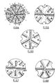
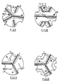
- Figures 3 to 14 are each a front end view of other bits all within the scope of the invention; and
- Figure 15 is a longitudinal sectional view of another bit of the invention, and Figure 16 is a sectional view taken on lines XVI-XVI on Figure 15.
- Where possible, the same reference numerals are used to designate the same parts in the different embodiments.
- The rotary bit body of Figures 1 and 2 comprises a leading bit end face 1 and a rearward end portion 2 for connection to a drill string, not shown. The intermediate portion comprises a gauge portion having three kickers 3. A bore 4 extends through the connection portion 2 and ends inside the bit. A number of
passageways 5 of relatively reduced diameter lead from the bore 4 to the edge or periphery of the bit face where they emerge as outlet nozzles 6: as shown in Figure 2 there are threesuch nozzles 6 spaced apart about the circumference of the bit end face. A number of blades 7 is present on the bit end face 1; as shown in Figure 2 there are six such blades 7, i.e. two blades per nozzle. Three of the blades. 7 A, extend radially from an outlet to towards the centre axis of the bit end face but stop short of reaching the centre point The other threeblades 78 lie between each pair ofblades 7A and meet at the centre point. Cutting elements C each comprising a polycrystalline diamond compact are mounted in a row on one side of each blade to present a cutting edge. Three junk slots 8 extend from the bit face 1 up past the kickers 3, the slots being located on the opposite side of theblade 7A from theadjacent nozzle 6. Because theblades 7A stop short of meeting theblades 7B at the centre point a gap G is defined. In use, drilling mud is pumped down the bore, and the mud flows along thepassageways 5 and out through eachnozzle 6. As the bit is rotated the cutting elements C of each blade cut or abrade the formation, producing chippings, not shown. The drilling mud from eachnozzle 6 flows in the channels defined by the blades 7 past the cutting elements C of theadjacent blade 7A, through the adjacent gap G, and past the cutting elements C of the adji!-,ent blade 7B and then up a junk slot 8. This is shown by the arrows. The chippings are removed efficiently and the formation is cooled. Thewall portions 7A dand 7B are thus arranged relative to thenozzle 6 so that the drilling mud flows towards the centre axis off the bit before exiting to the gauge region. The mud from each nozzle serves to clean two sets of cutting elements. The mud flows in a single common and unbranched path so, should a blockage occur in the path, there is no escape route for the fluid and as a result pressure builds up in the fluid tending to clear the blockage away. - In the bit of Figure 3, four
outlet nozzles 6 are present, and there are a total of eight blades 7. Theblades 7B meet at the centre point and are well supported, which of course would not be possible if the bore 4 emerged there and this offers many advantages in terms of bit design, manufacture and strength. The blades 7C are joined to theblades 7B by fences F which separate the channels and add strength. - In the bit of Figure 4, there are three
nozzle outlets 6, but a total of twelve wall portions. The blades join the kickers 8 except for blades 7D where there is agap connecting channels 10 and 11. As a result there is a single path fromnozzle 6 to the junk slot 8 throughchannels 9, 10, 11 and 12. The bit has four blades per nozzle, useful for large diameter bits e.g. above 44 cm. - In the bit of Figure 5, there are four
nozzle outlets 6 and siz wall portions. As shown by the arrows, the mud is arranged to flow from twooutlets 6 into one junk slot 8, so increasing fluid velocity and the cleaning and cooling effect. - In the embodiment of Figure 6,
auxiliary nozzles 6A are present to enhance the cleaning action on the second set of cutting elements be releasing auxiliary drilling mud in the gap G. - In the embodioment of Figure 7, the flow of mud is caused to pass over four sets of cutting elements before exiting via a junk slot 8. The blades 7D do not reach the kickers and are joined at the centre by fences F.
- In the embodiment of Figure 8, the
nozzle openings 6 are in the central region of the bit face and the fluid is directed to travel away from the central axis and then towards it before exiting in the gauge region. - In the embodiment of Figure 9, there are three junk slots 8. In the case of the
nozzle 68 the mud cleans only one set of cutting elements and then goes direct to the facing junk slot 8; in the case of theother outlet nozzles 6 the mud passes two sets of cutting elements. A fence F is present to increase the fluid velocity in front of theblade 7A. - In the embodiment of Figure 10, the fence F1 increases the mud velocity in front of the
blade 7A. The fences F join theblades 7A to theblades 7B to separate the path from thenozzle 6A from that of the nozzle 6B. - In the embodiment of Figure 11, a fence F1 is provided adjacent the junk slot 8 to direct the flow of mud past the cutting elements from
outlet nozzles 6 which would otherwise need to be positioned nearer to the central axis. - In the embodiment of Figure 12, the fences F1 extend from adjacent the outlet to the junk slot better to define the clear flow path. In the embodiment of Figure 13, the blades are curved, permitting cutting elements to be orientated with non- zero side rake angles while still being in mutual alignment with their neighbours.
- In the embodiment of Figure 14, there is a small centre
non-interchangeable nozzle 6C to clean the central cutters and join the flow from themain nozzle 6. It will be noticed that the fluid emerging fromnozzle 6C will tend to divide. The bit includes leakage paths of small cross-sectional area between theblades 7A. - In the embodiment shown in Figures 15 and 16 the bit includes a restrictor 13 on the surface of the bit whose restricted cross-sectional area is bounded partly by part of the bit body and partly by the formation of rock being drilled.
Claims (9)
Applications Claiming Priority (2)
| Application Number | Priority Date | Filing Date | Title |
|---|---|---|---|
| GB8226466 | 1982-09-16 | ||
| GB8226466 | 1982-09-16 |
Publications (2)
| Publication Number | Publication Date |
|---|---|
| EP0119239A1 EP0119239A1 (en) | 1984-09-26 |
| EP0119239B1 true EP0119239B1 (en) | 1986-11-12 |
Family
ID=10532961
Family Applications (1)
| Application Number | Title | Priority Date | Filing Date |
|---|---|---|---|
| EP83902959A Expired EP0119239B1 (en) | 1982-09-16 | 1983-09-16 | Rotary drill bits |
Country Status (8)
| Country | Link |
|---|---|
| US (1) | US4577706A (en) |
| EP (1) | EP0119239B1 (en) |
| JP (1) | JPS59501869A (en) |
| AU (1) | AU569259B2 (en) |
| CA (1) | CA1217475A (en) |
| DE (1) | DE3367648D1 (en) |
| NO (1) | NO841917L (en) |
| WO (1) | WO1984001186A1 (en) |
Families Citing this family (25)
| Publication number | Priority date | Publication date | Assignee | Title |
|---|---|---|---|---|
| GB2148978B (en) * | 1983-10-29 | 1987-01-07 | Nl Petroleum Prod | Improvements in or relating to rotary drill bits |
| GB8418482D0 (en) * | 1984-07-19 | 1984-08-22 | Nl Petroleum Prod | Rotary drill bits |
| US4727946A (en) * | 1984-10-26 | 1988-03-01 | Nl Industries, Inc. | Rotary drill bits |
| GB8524146D0 (en) * | 1985-10-01 | 1985-11-06 | Nl Petroleum Prod | Rotary drill bits |
| US4856601A (en) * | 1986-01-22 | 1989-08-15 | Raney Richard C | Drill bit with flow control means |
| US4714120A (en) * | 1986-01-29 | 1987-12-22 | Hughes Tool Company | Diamond drill bit with co-joined cutters |
| US4913244A (en) * | 1986-09-11 | 1990-04-03 | Eastman Christensen Company | Large compact cutter rotary drill bit utilizing directed hydraulics for each cutter |
| US4883136A (en) * | 1986-09-11 | 1989-11-28 | Eastman Christensen Co. | Large compact cutter rotary drill bit utilizing directed hydraulics for each cutter |
| USD307279S (en) | 1986-10-16 | 1990-04-17 | Eastman Christensen Company | Cutting tooth for a rotating drag bit |
| EP0395769A4 (en) * | 1988-11-14 | 1991-11-06 | Ministerstvo Gazovoi Promyshlennosti Sssr | Boring bit |
| GB2252574B (en) * | 1991-02-01 | 1995-01-18 | Reed Tool Co | Rotary drill bits and methods of designing such drill bits |
| US5238075A (en) * | 1992-06-19 | 1993-08-24 | Dresser Industries, Inc. | Drill bit with improved cutter sizing pattern |
| GB2277760B (en) * | 1993-05-08 | 1996-05-29 | Camco Drilling Group Ltd | Improvements in or relating to rotary drill bits |
| DE69531431T2 (en) * | 1994-10-15 | 2004-07-01 | Camco Drilling Group Ltd., Stonehouse | A rotary drill bit |
| GB9509555D0 (en) * | 1995-05-11 | 1995-07-05 | Camco Drilling Group Ltd | Improvements in or relating to rotary drill bits |
| US5904213A (en) * | 1995-10-10 | 1999-05-18 | Camco International (Uk) Limited | Rotary drill bits |
| US6089336A (en) * | 1995-10-10 | 2000-07-18 | Camco International (Uk) Limited | Rotary drill bits |
| US5794725A (en) * | 1996-04-12 | 1998-08-18 | Baker Hughes Incorporated | Drill bits with enhanced hydraulic flow characteristics |
| US6021858A (en) * | 1996-06-05 | 2000-02-08 | Smith International, Inc. | Drill bit having trapezium-shaped blades |
| US5957228A (en) * | 1997-09-02 | 1999-09-28 | Smith International, Inc. | Cutting element with a non-planar, non-linear interface |
| US6971459B2 (en) | 2002-04-30 | 2005-12-06 | Raney Richard C | Stabilizing system and methods for a drill bit |
| US8936109B2 (en) | 2010-06-24 | 2015-01-20 | Baker Hughes Incorporated | Cutting elements for cutting tools |
| US8327957B2 (en) * | 2010-06-24 | 2012-12-11 | Baker Hughes Incorporated | Downhole cutting tool having center beveled mill blade |
| JP2012127062A (en) * | 2010-12-13 | 2012-07-05 | Mitsubishi Materials Corp | Drilling bit |
| EP3433463B1 (en) * | 2016-03-22 | 2020-07-01 | TerraRoc Finland Oy | Down-the-hole drilling device |
Family Cites Families (9)
| Publication number | Priority date | Publication date | Assignee | Title |
|---|---|---|---|---|
| US3112803A (en) * | 1962-01-02 | 1963-12-03 | Jersey Prod Res Co | Diamond drill bit |
| US3215215A (en) * | 1962-08-27 | 1965-11-02 | Exxon Production Research Co | Diamond bit |
| DE1199209B (en) * | 1963-12-30 | 1965-08-26 | Erdoel Und Erdgaserkundung Veb | Nozzle chisel |
| US3308896A (en) * | 1964-08-20 | 1967-03-14 | Homer I Henderson | Drilling bit |
| US4098363A (en) * | 1977-04-25 | 1978-07-04 | Christensen, Inc. | Diamond drilling bit for soft and medium hard formations |
| DE2814165C2 (en) * | 1978-04-01 | 1980-04-30 | Bochumer Eisenhuette Heintzmann Gmbh & Co, 4630 Bochum | High pressure water nozzle |
| US4397363A (en) * | 1980-01-10 | 1983-08-09 | Drilling & Service U.K. Limited | Rotary drill bits and method of use |
| US4336850A (en) * | 1980-09-12 | 1982-06-29 | Christensen, Inc. | Internal fluid screen to prevent nozzle and port plugging |
| DE3039633C2 (en) * | 1980-10-21 | 1983-08-18 | Christensen, Inc., 84115 Salt Lake City, Utah | Rotary drill bits, in particular for deep drilling |
-
1983
- 1983-09-15 CA CA000436741A patent/CA1217475A/en not_active Expired
- 1983-09-16 WO PCT/GB1983/000227 patent/WO1984001186A1/en not_active Ceased
- 1983-09-16 JP JP58502994A patent/JPS59501869A/en active Pending
- 1983-09-16 EP EP83902959A patent/EP0119239B1/en not_active Expired
- 1983-09-16 AU AU20376/83A patent/AU569259B2/en not_active Ceased
- 1983-09-16 US US06/611,008 patent/US4577706A/en not_active Expired - Lifetime
- 1983-09-16 DE DE8383902959T patent/DE3367648D1/en not_active Expired
-
1984
- 1984-05-14 NO NO841917A patent/NO841917L/en unknown
Also Published As
| Publication number | Publication date |
|---|---|
| WO1984001186A1 (en) | 1984-03-29 |
| EP0119239A1 (en) | 1984-09-26 |
| JPS59501869A (en) | 1984-11-08 |
| NO841917L (en) | 1984-05-14 |
| US4577706A (en) | 1986-03-25 |
| CA1217475A (en) | 1987-02-03 |
| DE3367648D1 (en) | 1987-01-02 |
| AU2037683A (en) | 1984-04-04 |
| AU569259B2 (en) | 1988-01-28 |
Similar Documents
| Publication | Publication Date | Title |
|---|---|---|
| US4577706A (en) | Rotary drill bits | |
| US6089336A (en) | Rotary drill bits | |
| US4515227A (en) | Nozzle placement in a diamond rotating bit including a pilot bit | |
| US4640374A (en) | Rotary drill bit | |
| EP0418706B1 (en) | Earth boring bit for soft to hard formations | |
| US4538691A (en) | Rotary drill bit | |
| US3215215A (en) | Diamond bit | |
| US4848491A (en) | Rotary drill bits | |
| US5103922A (en) | Fishtail expendable diamond drag bit | |
| EP0219992B1 (en) | Improvements in or relating to rotary drill bits | |
| US5819860A (en) | Rotary drill bits | |
| US8100201B2 (en) | Rotary drill bit | |
| EP0032791B1 (en) | Rotary drill bits | |
| CN112513406B (en) | Downhole tool with fixed cutter for rock removal | |
| EP0974730B1 (en) | Rotary dag bit | |
| EP0624708B1 (en) | Nozzle arrangement for drag type drill bit | |
| CA1246049A (en) | Rotary drill bits | |
| US6065553A (en) | Split blade rotary drag type drill bits | |
| US20100276206A1 (en) | Rotary Drill Bit | |
| EP0192016B1 (en) | Rotary drill bit | |
| US11377911B2 (en) | Fixed cutter drill bits including nozzles with end and side exits |
Legal Events
| Date | Code | Title | Description |
|---|---|---|---|
| PUAI | Public reference made under article 153(3) epc to a published international application that has entered the european phase |
Free format text: ORIGINAL CODE: 0009012 |
|
| 17P | Request for examination filed |
Effective date: 19840626 |
|
| AK | Designated contracting states |
Designated state(s): BE CH DE FR GB LI NL SE |
|
| GRAA | (expected) grant |
Free format text: ORIGINAL CODE: 0009210 |
|
| AK | Designated contracting states |
Kind code of ref document: B1 Designated state(s): BE CH DE FR GB LI NL SE |
|
| REF | Corresponds to: |
Ref document number: 3367648 Country of ref document: DE Date of ref document: 19870102 |
|
| ET | Fr: translation filed | ||
| PLBE | No opposition filed within time limit |
Free format text: ORIGINAL CODE: 0009261 |
|
| STAA | Information on the status of an ep patent application or granted ep patent |
Free format text: STATUS: NO OPPOSITION FILED WITHIN TIME LIMIT |
|
| 26N | No opposition filed | ||
| PGFP | Annual fee paid to national office [announced via postgrant information from national office to epo] |
Ref country code: SE Payment date: 19890619 Year of fee payment: 7 |
|
| PGFP | Annual fee paid to national office [announced via postgrant information from national office to epo] |
Ref country code: CH Payment date: 19890927 Year of fee payment: 7 |
|
| PG25 | Lapsed in a contracting state [announced via postgrant information from national office to epo] |
Ref country code: SE Effective date: 19900917 |
|
| PG25 | Lapsed in a contracting state [announced via postgrant information from national office to epo] |
Ref country code: LI Effective date: 19900930 Ref country code: CH Effective date: 19900930 |
|
| REG | Reference to a national code |
Ref country code: CH Ref legal event code: PL |
|
| PGFP | Annual fee paid to national office [announced via postgrant information from national office to epo] |
Ref country code: GB Payment date: 19930907 Year of fee payment: 11 |
|
| PGFP | Annual fee paid to national office [announced via postgrant information from national office to epo] |
Ref country code: FR Payment date: 19930909 Year of fee payment: 11 |
|
| PGFP | Annual fee paid to national office [announced via postgrant information from national office to epo] |
Ref country code: NL Payment date: 19930930 Year of fee payment: 11 |
|
| PG25 | Lapsed in a contracting state [announced via postgrant information from national office to epo] |
Ref country code: GB Effective date: 19940916 |
|
| EUG | Se: european patent has lapsed |
Ref document number: 83902959.2 Effective date: 19910527 |
|
| PG25 | Lapsed in a contracting state [announced via postgrant information from national office to epo] |
Ref country code: NL Effective date: 19950401 |
|
| GBPC | Gb: european patent ceased through non-payment of renewal fee |
Effective date: 19940916 |
|
| NLV4 | Nl: lapsed or anulled due to non-payment of the annual fee | ||
| PG25 | Lapsed in a contracting state [announced via postgrant information from national office to epo] |
Ref country code: FR Effective date: 19950531 |
|
| REG | Reference to a national code |
Ref country code: FR Ref legal event code: ST |
|
| PGFP | Annual fee paid to national office [announced via postgrant information from national office to epo] |
Ref country code: DE Payment date: 20020925 Year of fee payment: 20 |
|
| PGFP | Annual fee paid to national office [announced via postgrant information from national office to epo] |
Ref country code: BE Payment date: 20021129 Year of fee payment: 20 |
|
| BE20 | Be: patent expired |
Owner name: NL *PETROLEUM PRODUCTS LTD Effective date: 20030916 |