EP0119085B1 - Photoelectric brain scanner and its use - Google Patents
Photoelectric brain scanner and its use Download PDFInfo
- Publication number
- EP0119085B1 EP0119085B1 EP19840301629 EP84301629A EP0119085B1 EP 0119085 B1 EP0119085 B1 EP 0119085B1 EP 19840301629 EP19840301629 EP 19840301629 EP 84301629 A EP84301629 A EP 84301629A EP 0119085 B1 EP0119085 B1 EP 0119085B1
- Authority
- EP
- European Patent Office
- Prior art keywords
- guide
- probe
- scanner according
- plug
- armoring
- Prior art date
- Legal status (The legal status is an assumption and is not a legal conclusion. Google has not performed a legal analysis and makes no representation as to the accuracy of the status listed.)
- Expired
Links
- 210000004556 brain Anatomy 0.000 title description 11
- 239000000523 sample Substances 0.000 claims description 30
- 230000003287 optical effect Effects 0.000 claims description 29
- 239000004020 conductor Substances 0.000 claims description 24
- 230000000149 penetrating effect Effects 0.000 claims description 11
- 239000000463 material Substances 0.000 claims description 7
- 230000037361 pathway Effects 0.000 claims description 6
- 238000006073 displacement reaction Methods 0.000 claims description 4
- 230000009467 reduction Effects 0.000 claims description 2
- 230000004044 response Effects 0.000 claims description 2
- 210000005013 brain tissue Anatomy 0.000 description 12
- 238000000576 coating method Methods 0.000 description 10
- 239000011248 coating agent Substances 0.000 description 9
- 239000003365 glass fiber Substances 0.000 description 6
- 229910001220 stainless steel Inorganic materials 0.000 description 6
- 239000010935 stainless steel Substances 0.000 description 6
- 210000000988 bone and bone Anatomy 0.000 description 4
- 210000001519 tissue Anatomy 0.000 description 4
- 230000002411 adverse Effects 0.000 description 3
- 238000010171 animal model Methods 0.000 description 3
- 239000011521 glass Substances 0.000 description 3
- 238000000034 method Methods 0.000 description 3
- 230000001681 protective effect Effects 0.000 description 3
- 239000003479 dental cement Substances 0.000 description 2
- 239000003814 drug Substances 0.000 description 2
- 229940079593 drug Drugs 0.000 description 2
- -1 polyethylene Polymers 0.000 description 2
- 229920000915 polyvinyl chloride Polymers 0.000 description 2
- 239000004800 polyvinyl chloride Substances 0.000 description 2
- 239000004065 semiconductor Substances 0.000 description 2
- 239000007787 solid Substances 0.000 description 2
- YCKRFDGAMUMZLT-UHFFFAOYSA-N Fluorine atom Chemical compound [F] YCKRFDGAMUMZLT-UHFFFAOYSA-N 0.000 description 1
- 101100293261 Mus musculus Naa15 gene Proteins 0.000 description 1
- 239000004698 Polyethylene Substances 0.000 description 1
- 239000000853 adhesive Substances 0.000 description 1
- 238000004026 adhesive bonding Methods 0.000 description 1
- 230000000712 assembly Effects 0.000 description 1
- 238000000429 assembly Methods 0.000 description 1
- 238000005842 biochemical reaction Methods 0.000 description 1
- 230000005540 biological transmission Effects 0.000 description 1
- 239000003990 capacitor Substances 0.000 description 1
- 238000004140 cleaning Methods 0.000 description 1
- 238000010276 construction Methods 0.000 description 1
- 239000006185 dispersion Substances 0.000 description 1
- 230000000694 effects Effects 0.000 description 1
- 238000003487 electrochemical reaction Methods 0.000 description 1
- 238000002474 experimental method Methods 0.000 description 1
- 229910052731 fluorine Inorganic materials 0.000 description 1
- 239000011737 fluorine Substances 0.000 description 1
- 230000004907 flux Effects 0.000 description 1
- 238000001802 infusion Methods 0.000 description 1
- 238000009413 insulation Methods 0.000 description 1
- 239000012212 insulator Substances 0.000 description 1
- 210000005036 nerve Anatomy 0.000 description 1
- 239000004014 plasticizer Substances 0.000 description 1
- 229920000573 polyethylene Polymers 0.000 description 1
- 229920000642 polymer Polymers 0.000 description 1
- 229920000098 polyolefin Polymers 0.000 description 1
- 229920001343 polytetrafluoroethylene Polymers 0.000 description 1
- 239000004810 polytetrafluoroethylene Substances 0.000 description 1
- 238000003825 pressing Methods 0.000 description 1
- 230000008569 process Effects 0.000 description 1
- 239000012858 resilient material Substances 0.000 description 1
- 239000011347 resin Substances 0.000 description 1
- 229920005989 resin Polymers 0.000 description 1
- 230000000717 retained effect Effects 0.000 description 1
- 238000005476 soldering Methods 0.000 description 1
- 230000002269 spontaneous effect Effects 0.000 description 1
- 125000000391 vinyl group Chemical group [H]C([*])=C([H])[H] 0.000 description 1
- 229920002554 vinyl polymer Polymers 0.000 description 1
Images

Classifications
-
- H—ELECTRICITY
- H02—GENERATION; CONVERSION OR DISTRIBUTION OF ELECTRIC POWER
- H02M—APPARATUS FOR CONVERSION BETWEEN AC AND AC, BETWEEN AC AND DC, OR BETWEEN DC AND DC, AND FOR USE WITH MAINS OR SIMILAR POWER SUPPLY SYSTEMS; CONVERSION OF DC OR AC INPUT POWER INTO SURGE OUTPUT POWER; CONTROL OR REGULATION THEREOF
- H02M3/00—Conversion of DC power input into DC power output
- H02M3/22—Conversion of DC power input into DC power output with intermediate conversion into AC
- H02M3/24—Conversion of DC power input into DC power output with intermediate conversion into AC by static converters
- H02M3/28—Conversion of DC power input into DC power output with intermediate conversion into AC by static converters using discharge tubes with control electrode or semiconductor devices with control electrode to produce the intermediate AC
-
- A—HUMAN NECESSITIES
- A61—MEDICAL OR VETERINARY SCIENCE; HYGIENE
- A61B—DIAGNOSIS; SURGERY; IDENTIFICATION
- A61B5/00—Measuring for diagnostic purposes; Identification of persons
- A61B5/0059—Measuring for diagnostic purposes; Identification of persons using light, e.g. diagnosis by transillumination, diascopy, fluorescence
-
- A—HUMAN NECESSITIES
- A61—MEDICAL OR VETERINARY SCIENCE; HYGIENE
- A61B—DIAGNOSIS; SURGERY; IDENTIFICATION
- A61B5/00—Measuring for diagnostic purposes; Identification of persons
- A61B5/145—Measuring characteristics of blood in vivo, e.g. gas concentration or pH-value ; Measuring characteristics of body fluids or tissues, e.g. interstitial fluid or cerebral tissue
- A61B5/1455—Measuring characteristics of blood in vivo, e.g. gas concentration or pH-value ; Measuring characteristics of body fluids or tissues, e.g. interstitial fluid or cerebral tissue using optical sensors, e.g. spectral photometrical oximeters
- A61B5/14551—Measuring characteristics of blood in vivo, e.g. gas concentration or pH-value ; Measuring characteristics of body fluids or tissues, e.g. interstitial fluid or cerebral tissue using optical sensors, e.g. spectral photometrical oximeters for measuring blood gases
- A61B5/14553—Measuring characteristics of blood in vivo, e.g. gas concentration or pH-value ; Measuring characteristics of body fluids or tissues, e.g. interstitial fluid or cerebral tissue using optical sensors, e.g. spectral photometrical oximeters for measuring blood gases specially adapted for cerebral tissue
Definitions
- the present invention generally relates to a system for scanning the brain tissues of an experimental animal.
- an apparatus having, as its essential components, a flexible cord assembly of a coated pair of optical conductors providing a probe for penetrating into brain tissues, a means for driving the probe and a photoelectric processor which provides light to be transmitted into the brain tissues and processes the light signal returned from the tissues to present the scanning results, e.g. as a chart.
- the above-mentioned read-out value or recorded chart i.e., "brain map”
- the spot is a limited brain region where (an) electrode(s) or (a) cannula(e)) is/are accurately placed or embedded.
- Drugs which can participate in or induce a biochemical reaction therein may be infused into the spot through the cannula.
- the embedded electrode may be used to supply the brain with electrical energy which stimulates the nerve fibres or initiates an electrochemical reaction therein.
- a photoelectric scanner which comprises a flexible cord assembly comprising two optical conductors, providing inward and outward pathways respectively, being coated with optically shielding material, forming a probe at one end of the assembly for penetrating into tissues and having an inlet and outlet plug at the other end of the assembly, the probe comprising a stepped armoring pipe which covers the outside of the optical conductors; and a photoelectric processor including a light source coupled to an inlet to the inward pathway, a photoelectric transducer coupled with an outlet of the outward pathway and producing an electric signal in response to light incident on the transducer, two sockets, each one having a casing to shield out exterior light and for holding one of the plugs, an amplifier adapted to receive as an input the electric signal, a recorder adapted to receive output signals from the amplifier, means for adjusting the gain of the amplifier, and a power source.
- such a scanner is characterised by means for driving the probe lengthwise and by means for detachably retaining a cannula-guide on the armoring pipe.
- the cannula guide is preferably held in position by a pair of clamps.
- the roots of the clamps may be fixed to the pipe at the root section and the tips thereof may extend to the penetrating section. Since the clamp is usually made of a resilient material it does not hinder the accommodating of the cannula guide but retains the cannula guide once it has been accommodated by pressing inwardly on it.
- the guide can then rest at the predetermined position of the penetrating section until it is forcibly pulled out.
- the upper part of the penetrating section of the probe may be expanded to form a lobe or the like and said expanded part is made sufficiently large to retain the inserted guide by outward pressure in order to fulfil the same object.
- twin inlet/outlet plugs each covered with an armoring-pipe.
- This armoring-pipe may also comprise at least two pipes of differing diameters arranged concentrically but offset longitudinally to form a "notched" configuration of which the diameter at the root section is larger than that of the smaller diameter section.
- Each of the plug armoring-pipes contains a single optical conductor (e.g. a glass fibre).
- the pair of optical conductors in the flexible cord assembly branch apart near said plug positions.
- the branched position and joints between the armoring-pipes and the flexible cord running through the armoring-pipes are usually reinforced by sheaths having approximately the same flexibility as that of the optical conductor.
- the material for this purpose may be, e.g., a thermal-shrinking polyvinyl chloride.
- both the light source and the photoelectric transducer are usually positioned such that they are functionally directed substantially upwardly (preferably in an upright or vertical direction) and are covered with sockets having cylindrical casings which stand upright thereon.
- Each of the sockets has a centre guide tube for holding the respective plug vertical while permitting a margin of angular displacement for the plug.
- the socket is high enough to guide the plug tip down to the focussing region of the light source or to the light receiving surface of the photoelectric transducer. This object can effectively be attained by approximating the depth of the throughhole through the centre guide tube down to said region or to the surface to the length of the small diameter section of the plug armoring-pipe.
- the light source may be an incandescent lamp (preferably with an interior lens) a light emitting diode or a semiconductor laser device, and a photomultiplier or a semiconductor photo detector may be used as the photoelectric transducer.
- the light source and the photoelectric transducer may be driven by a stabilized power source placed in the processor, an electric signal produced in the photoelectric transducer being supplied via an amplifier (containing one or more normal operational amplifiers) to a recorder which may produce a desired chart.
- an amplifier containing one or more normal operational amplifiers
- the previously-described extremely thin single optical conductors are usually made of glass and are easy to insert into and pierce through the rigid thin pipes, and no problem results therefrom in the structuring the probe and plugs encased in the rigid armoring-pipe.
- the thinnest of commercially available rigid pipes for instance, a stainless steel thin pipe of about 300-320 Il m outside diameter and about 120-150 ⁇ m inside diameter, may be selected for structuring these armoring pipes.
- each of the thin pipe assemblies which constitute a plug armoring-pipe encloses a single optical conductor for gluing.
- the plugs ensure a stable connection with the light source or with the photoelectric transducer.
- This accommodated state can be maintained without any additional means for retaining the plugs, and the latter are permitted a limited extent of angular displacement without producing any adverse effect on the optical connections.
- This feature is of particular importance because the scanning operation inevitably entails occasionally minute movements of an associated implement such as a stereotaxic instrument which carries and holds the animal (e.g. a rat) brain thereon and of a probe driving implement as an attachment to the stereotaxic instrument with respect to the photoelectric processor. Such movement may cause troubles in the plug's accommodated state.
- the optical conductor enclosed in the flexible cord assembly is extremely thin and fragile if it is made of glass, particular care should be exercised in handling the same. Moreover, the signal/noise ratio may adversely be affected by exterior light if it is used in the naked state.
- the coating is preferably a flexible tube made of a light insulator of relatively low coefficient of friction in order to facilitate the coating (sheathing) operation. Suitable materials are, e.g., polyolefins such as polyethylene and fluorine-containing polymers such as polytetrafluoroethylene.
- the branched position of the flexible segment of the cord and the joints between the armoring-pipes and the flexible coating are preferably reinforced by sheaths having approximately the same flexibility as that of the optical conductor in order to give sufficient deflective strength to the conductor.
- a suitable material for this is preferably polyvinyl chloride containing a controlled amount of plasticizer, particularly, a thermal-shrinking vinyl resin such as that conventionally used for cylindrical solid resistors or wound-type film capacitors.
- the armoring-pipe of the probe is structured to retain a detachable cannula-guide or other guide at least temporarily.
- cannula-guide as used throughout this specification including the claims should be broadly construed such that the function of the guide is not necessarily restricted to the guiding of a cannula or cannulae, but may have other or alternative guiding functions useful to those skilled in the art.
- the guide may also be a simple thin stainless steel pipe with both ends open, similar to that used for the armoring pipe.
- the detachable cannula guide accomodated on the penetrating section of the armoring-pipe may be glued to the cranial bones around its periphery with dental cement or the like, and when the operation is completed by pulling the probe out from the brain the guide is then left unmoved on the cranial bones as a cannula guide which may subsequently be used in accurately positioning a cannula for e.g. drug infusion.
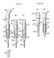
- FIG. 4A, 4B and 4C are sectional views showing the parts which constitute the flexible cord assembly, 4A specifically representing the probe for penetrating into brain tissue, 4B representing the branched position of the flexible cord, and 4C representing the plug, respectively.
- FIG. 5A, 5B and 5C is an enlarged schematic view of the armoring-pipe of the probe with a clamp means built in accordance with a preferred embodiment and showing the manner of accommodating the cannula guide thereto at varying stages of the accommodating or detaching operation.
- FIGs. 6A and 6B are enlarged partial schematic views representing the section of the probe encased in the armoring-pipe equipped with an alternative for retaining the cannula guide.
- Fig. 1 which illustrates the entire arrangement for the brain tissue scanning operation
- a stereotaxic instrument 2 which may be any commercially available type, a photoelectric processor 1, a flexible cord assembly 3 and means 4 for driving the probe which, in combination, constitute a photoelectric brain scanner.
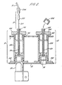
- twin sockets 11 and 12 having centre-guide-tubes 115 and 125 which provide through holes 111 and 121 for receiving twin plugs 31 of the flexible cord assembly 3, respectively. Both the sockets 11 and 12 are mounted on an abutment 13 placed in the housing of the processor 1 in the proximity of the side wall covering a light source 15 (an incandescent lamp, LNS-SB12-71X, available from Hamai Denkyu K.K.) and a photoelectric transducer 16 (Optical detector, 509-50, available from Bell Howell Co., Ltd.).
- a light source 15 an incandescent lamp, LNS-SB12-71X, available from Hamai Denkyu K.K.
- a photoelectric transducer 16 Optical detector, 509-50, available from Bell Howell Co., Ltd.
- a pen-writing recorder 17 (SR 6402, available from Watanabe Sokki K.K.) and a mains power switch 18 which also serves as a working indicator.
- Numeral 19 represents a knob for gain adjustment of the amplifier (not shown) and numeral 20 indicates a knob for zero-point adjustment of the recorder 17.
- Numeral 21 represents a change-over switch for the means for driving the probe (probe driving means) 4 which functions as the power supply control as well as the driving direction selector and numeral 22 represents a knob for adjusting the driving speed.
- the probe driving means 4 consists of a reduction geared motor 42 detachably mounted on a commercially available stereotaxic instrument 2 for the rat brain (Takahashi Shoten) through a bracket 41, a rotating adaptor 44 attached to the axis of the fine adjustment device 45 of the stereotaxic instrument 2 and a flexible shaft 43 which couples said rotating adaptor 44 with the rotating shaft of the motor 42, which is supplied with electric current from the main circuitry in the processor 1 under the control of switch 21 and knob 22.
- Fig. 2 shows details of the sockets 11 and 12 together with their associated components.
- Cylindrical casings 113 and 123 are threaded into flanges 112 and 122 fastened to the abutment 13 at their bottom ends, while their top ends project from the ceiling (top panel) of the housing of the processor 1 through through holes 101 and 102 and are closed with lids 114 and 125, respectively, which are secured to the casings by threading.
- guide-tubes 115 and 125 are fixed in the casings 113 and 123.
- the guide-tubes 115 and 125 in turn, provide through holes 111 and 121 for accommodating the plugs 31 of the flexible cord assembly 3.
- the socket 11 shown in the left side of Fig. 2 is shown with plugs 31 inserted midway. Since the plug 31 has a stepped configuration and the length of the smallest diameter section 311 is adjusted as previously described, the tip of the plug 31 reaches the focussing region of the light source 15 when the plug 31 is inserted until the shoulder of the notch touches the top edge of the guide tube 115. In the case of the right side socket 12, wherein the photoelectric transducer 16 is shown, the length is so adjusted that the distal end of the optical conductor may be brought in close contact with the light receiving surface of the photoelectric transducer 16.
- a cap schematically shown and referenced by numeral 126 may be provided to cover the top open end of the guide tube 125 in the non-used state and a similar means may also be provided in the left side socket to cover the open end of the guide tube 115.
- sockets 11 and 12 comprise flanges 112 and 122, the guide-tubes 115 and 125, the casings 113 and 123, and the lids 114 and 124 for easy assembly and disassembly, cleaning operations for the light source 15 and the upper surface of the photoelectric transducer 16 as well as detaching operations for the top wall (ceiling) of the processor 1 are also made very easy.
- these casings, guide-tubes and lids may be structured integrally as a solid body.
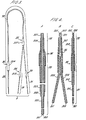
- the flexible cord assembly 3 generally shown in Fig. 3 comprises of a probe 33 for penetrating into the brain tissues, twin plugs 31 and a flexible cord 32 which connects the probe 33 with the terminals 31.
- a probe 33 for penetrating into the brain tissues
- twin plugs 31 and a flexible cord 32 which connects the probe 33 with the terminals 31.
- the flexible and light- insulating coating 321 and 322 which covers the flexible cord 32 of the assembly 3
- sheaths 313 and 334 near the joints 34 and 36 and sheath 351 near the branched position 35 of the flexible cord 32.
- FIG. 4A The cross-sectional views of Figs. 4A, 4B and 4C illustrate the details of the parts which constitute the flexible cord assembly.
- a pair of glass fibres 301 and 302 are enclosed in a multiply-notched armoring-pipe comprising thin stainless steel pipes 331, 332 and 333 concentrically arranged and glued together with glass fibres 301 and 302.
- the thinnest pipe 331 usually has an outside diameter of about 320 ⁇ m, and the other pipes 332 and 33, have correspondingly larger diameters so that they can be set in close fitting.
- the intermediate diameter pipe 332 may be shorter than the other pipes 331 and 333 so that the tip of the flexible and light-shielding coating 321 can suitably be sandwiched between the butt ends of the pipes 331 and 333.
- the region 36 where the flexible coating joins the armoring-pipe is reinforced by protective sheath 334.
- the pair of glass fibres 301 and 302 and the flexible and light-shielding coating 321 are likewise separated into twin single glass fibres 301 and 302, respectively covered with coatings 323 and 322.
- the glass fibre 301 is enclosed in an armoring-pipe comprising a stainless steel pipe of smaller diameter 311 and one of large diameter 312 concentrically arranged but offset longitudinally with respect to each other to form a notched configuration.
- the construction thereof is similar to but simpler than that of the probe 33 and all of the components at the joints 34 are reinforced by a protective sheath 313.
- the tip of smaller diameter stainless steel pipe 312 and the coating 322 are butted together and sandwiched between the smaller diameter pipe 311 and sheath 313.
- the guide 39 may be glued to the cranial bones of the experimental animal with e.g. dental cement, and when a searching operation is completed by pulling the probe 3 out from the brain guide 39 is left glued to the bones by reversing the order of events shown in Figs. 5A, B and C.
Landscapes
- Health & Medical Sciences (AREA)
- Life Sciences & Earth Sciences (AREA)
- Physics & Mathematics (AREA)
- Engineering & Computer Science (AREA)
- Molecular Biology (AREA)
- General Health & Medical Sciences (AREA)
- Pathology (AREA)
- Biomedical Technology (AREA)
- Heart & Thoracic Surgery (AREA)
- Medical Informatics (AREA)
- Veterinary Medicine (AREA)
- Surgery (AREA)
- Animal Behavior & Ethology (AREA)
- Biophysics (AREA)
- Public Health (AREA)
- Power Engineering (AREA)
- Neurology (AREA)
- Spectroscopy & Molecular Physics (AREA)
- Optics & Photonics (AREA)
- Measurement Of The Respiration, Hearing Ability, Form, And Blood Characteristics Of Living Organisms (AREA)
- Investigating Or Analysing Materials By Optical Means (AREA)
Description
- The present invention generally relates to a system for scanning the brain tissues of an experimental animal. In particular, it is concerned with an apparatus having, as its essential components, a flexible cord assembly of a coated pair of optical conductors providing a probe for penetrating into brain tissues, a means for driving the probe and a photoelectric processor which provides light to be transmitted into the brain tissues and processes the light signal returned from the tissues to present the scanning results, e.g. as a chart.
- It has been suggested to scan the brain tissues of an experimental animal by detecting the difference in reflectance in a particular site of the brain tissue while a pair of glass optical fibres is advanced through the brain. Light is transmitted through one of a pair of the optical fibres to a spot in the tissue where the light is reflected or dispersed. Only the reflected light is picked up at the distal end of the pair and sent back through the other of the pair to be sensed and read. As the tip of the pair of fibres advances, the read-out signal varies accordingly, and may be recorded by any means such as e.g. a pen-writing recorder.
- Since the brain tissue usually had characteristically different conditions for light dispersion or reflection at its specific locality, the above-mentioned read-out value or recorded chart, i.e., "brain map", supplied detailed information about the brain tissue. Thus, a spot in the tissue can be specified and made an indicator for conducting subsequent experiments. The spot is a limited brain region where (an) electrode(s) or (a) cannula(e)) is/are accurately placed or embedded.
- Drugs which can participate in or induce a biochemical reaction therein may be infused into the spot through the cannula. In addition to the pick-up of spontaneous biological electrical signals from the brain tissue, the embedded electrode may be used to supply the brain with electrical energy which stimulates the nerve fibres or initiates an electrochemical reaction therein.
- The fundamental concept of this valuable technique has already been disclosed by the present inventors (see, for instance, Journal of Neuro- science Method, 2, (1980), 9-17). The present inventors have now developed a practically useful system for scanning brain tissues.
- It is known from EP-A-0047094 to provide a photoelectric scanner which comprises a flexible cord assembly comprising two optical conductors, providing inward and outward pathways respectively, being coated with optically shielding material, forming a probe at one end of the assembly for penetrating into tissues and having an inlet and outlet plug at the other end of the assembly, the probe comprising a stepped armoring pipe which covers the outside of the optical conductors; and a photoelectric processor including a light source coupled to an inlet to the inward pathway, a photoelectric transducer coupled with an outlet of the outward pathway and producing an electric signal in response to light incident on the transducer, two sockets, each one having a casing to shield out exterior light and for holding one of the plugs, an amplifier adapted to receive as an input the electric signal, a recorder adapted to receive output signals from the amplifier, means for adjusting the gain of the amplifier, and a power source.
- According to the invention such a scanner is characterised by means for driving the probe lengthwise and by means for detachably retaining a cannula-guide on the armoring pipe.
- The cannula guide is preferably held in position by a pair of clamps. The roots of the clamps may be fixed to the pipe at the root section and the tips thereof may extend to the penetrating section. Since the clamp is usually made of a resilient material it does not hinder the accommodating of the cannula guide but retains the cannula guide once it has been accommodated by pressing inwardly on it. The guide can then rest at the predetermined position of the penetrating section until it is forcibly pulled out. Alternatively, the upper part of the penetrating section of the probe may be expanded to form a lobe or the like and said expanded part is made sufficiently large to retain the inserted guide by outward pressure in order to fulfil the same object.
- In a preferred embodiment of the invention, at the other end of the optical conductors of the flexible cord assembly are twin inlet/outlet plugs each covered with an armoring-pipe. This armoring-pipe may also comprise at least two pipes of differing diameters arranged concentrically but offset longitudinally to form a "notched" configuration of which the diameter at the root section is larger than that of the smaller diameter section. Each of the plug armoring-pipes contains a single optical conductor (e.g. a glass fibre). The pair of optical conductors in the flexible cord assembly branch apart near said plug positions. The branched position and joints between the armoring-pipes and the flexible cord running through the armoring-pipes are usually reinforced by sheaths having approximately the same flexibility as that of the optical conductor. The material for this purpose may be, e.g., a thermal-shrinking polyvinyl chloride.
- In the photoelectric processor, both the light source and the photoelectric transducer are usually positioned such that they are functionally directed substantially upwardly (preferably in an upright or vertical direction) and are covered with sockets having cylindrical casings which stand upright thereon. Each of the sockets has a centre guide tube for holding the respective plug vertical while permitting a margin of angular displacement for the plug. The socket is high enough to guide the plug tip down to the focussing region of the light source or to the light receiving surface of the photoelectric transducer. This object can effectively be attained by approximating the depth of the throughhole through the centre guide tube down to said region or to the surface to the length of the small diameter section of the plug armoring-pipe.
- The light source may be an incandescent lamp (preferably with an interior lens) a light emitting diode or a semiconductor laser device, and a photomultiplier or a semiconductor photo detector may be used as the photoelectric transducer.
- In practice, only a fraction (e.g. barely one tenth) of the whole light flux produced can be transmitted along the optical conductor and a fraction (e.g. barely only one tenth) of the light receiving surface can be utilized for receiving the light incident thereon. This drawback can however be offset by amplifying the fractional photoelectric current by means of an internal amplifier for the photoelectric transducer and by a subsequent amplifier.
- What is important here is the centering of the optical axis of the light source to the axis of the optical conductor and maintaining the light receiving surface perpendicular to the axis of the optical conductor while shielding these optical connections from exterior light. It is also important to design these components so that the connection of the plug with and disconnection of that from the photoelectric processor can be performed in a simple and easy operation with sufficient accuracy and so that rotating movement of the plug armoring-pipe in the connected state relative to the processor may be performed to a limited extent without adversely affecting the transmission of a light signal therethrough.
- The light source and the photoelectric transducer may be driven by a stabilized power source placed in the processor, an electric signal produced in the photoelectric transducer being supplied via an amplifier (containing one or more normal operational amplifiers) to a recorder which may produce a desired chart.
- The previously-described extremely thin single optical conductors are usually made of glass and are easy to insert into and pierce through the rigid thin pipes, and no problem results therefrom in the structuring the probe and plugs encased in the rigid armoring-pipe. Thus, the thinnest of commercially available rigid pipes, for instance, a stainless steel thin pipe of about 300-320 Ilm outside diameter and about 120-150 µm inside diameter, may be selected for structuring these armoring pipes.
- Inside the rigid pipe assembly which constitutes the armoring-pipe of the probe, usually two optical conductors are arranged in parallel with each other and glued together with an adhesive agent of the instant hardening type in such a manner that the distal ends are even. Each of the thin pipe assemblies which constitute a plug armoring-pipe encloses a single optical conductor for gluing. By virtue of the previously described stepped configuration, the plugs ensure a stable connection with the light source or with the photoelectric transducer. Thus, by simply inserting the plug armoring-pipes into the centre through holes of the sockets until the shoulders of the steps rest on the upper edges of the respective guide tube, the respective plug reaches the light receiving surface of the photoelectric transducer or the focussing region of the light source, as appropriate.
- This accommodated state can be maintained without any additional means for retaining the plugs, and the latter are permitted a limited extent of angular displacement without producing any adverse effect on the optical connections. This feature is of particular importance because the scanning operation inevitably entails occasionally minute movements of an associated implement such as a stereotaxic instrument which carries and holds the animal (e.g. a rat) brain thereon and of a probe driving implement as an attachment to the stereotaxic instrument with respect to the photoelectric processor. Such movement may cause troubles in the plug's accommodated state.
- Since the optical conductor enclosed in the flexible cord assembly is extremely thin and fragile if it is made of glass, particular care should be exercised in handling the same. Moreover, the signal/noise ratio may adversely be affected by exterior light if it is used in the naked state. Thus, it is preferred to coat the optical conductor in the flexible segment with a suitable material to protect against mechanical impact. This coating can also give suitable light-insulation in the flexible cord segment. The coating is preferably a flexible tube made of a light insulator of relatively low coefficient of friction in order to facilitate the coating (sheathing) operation. Suitable materials are, e.g., polyolefins such as polyethylene and fluorine-containing polymers such as polytetrafluoroethylene.
- The branched position of the flexible segment of the cord and the joints between the armoring-pipes and the flexible coating are preferably reinforced by sheaths having approximately the same flexibility as that of the optical conductor in order to give sufficient deflective strength to the conductor. A suitable material for this is preferably polyvinyl chloride containing a controlled amount of plasticizer, particularly, a thermal-shrinking vinyl resin such as that conventionally used for cylindrical solid resistors or wound-type film capacitors.
- In accordance with the present invention, the armoring-pipe of the probe is structured to retain a detachable cannula-guide or other guide at least temporarily. The term "cannula-guide" as used throughout this specification including the claims should be broadly construed such that the function of the guide is not necessarily restricted to the guiding of a cannula or cannulae, but may have other or alternative guiding functions useful to those skilled in the art. The guide may also be a simple thin stainless steel pipe with both ends open, similar to that used for the armoring pipe.
- During the scanning operation, the detachable cannula guide accomodated on the penetrating section of the armoring-pipe may be glued to the cranial bones around its periphery with dental cement or the like, and when the operation is completed by pulling the probe out from the brain the guide is then left unmoved on the cranial bones as a cannula guide which may subsequently be used in accurately positioning a cannula for e.g. drug infusion.
- The present invention will now be described and illustrated in more detail by referring to preferred embodiments shown in the attached drawings, in which most of the components are designated by the same reference numerals throughout the drawings.
- Fig. 1, not intended to represent an embodiment of the invention but included to show how the invention is put in practice, is a perspective view schematically showing the entire arrangement of a photoelectric brain scanner together - with associated implements.
- Fig. 2, not intended to represent an embodiment of the invention but included to show how the invention is put in practice, is a side sectional view of sockets and associated components inside the housing of the photoelectric processor seen in Fig. 1.
- Fig. 3, not intended to represent an embodiment of the invention but included to show how the invention is put in practice, is a schematic view showing the flexible cord assembly of the scanner shown in Fig. 1.
- Each of Figs. 4A, 4B and 4C, not intended to represent an embodiment of the invention but included to show how the invention is put in practice, is a sectional view showing the parts which constitute the flexible cord assembly, 4A specifically representing the probe for penetrating into brain tissue, 4B representing the branched position of the flexible cord, and 4C representing the plug, respectively.
- Each of Figs. 5A, 5B and 5C is an enlarged schematic view of the armoring-pipe of the probe with a clamp means built in accordance with a preferred embodiment and showing the manner of accommodating the cannula guide thereto at varying stages of the accommodating or detaching operation.
- Finally, Figs. 6A and 6B are enlarged partial schematic views representing the section of the probe encased in the armoring-pipe equipped with an alternative for retaining the cannula guide.
- In Fig. 1 which illustrates the entire arrangement for the brain tissue scanning operation, there is a stereotaxic instrument 2 which may be any commercially available type, a photoelectric processor 1, a
flexible cord assembly 3 and means 4 for driving the probe which, in combination, constitute a photoelectric brain scanner. - In the photoelectric processor 1, there are
twin sockets tubes holes flexible cord assembly 3, respectively. Both thesockets abutment 13 placed in the housing of the processor 1 in the proximity of the side wall covering a light source 15 (an incandescent lamp, LNS-SB12-71X, available from Hamai Denkyu K.K.) and a photoelectric transducer 16 (Optical detector, 509-50, available from Bell Howell Co., Ltd.). - On the front panel of the housing of the processor 1, is a pen-writing recorder 17 (SR 6402, available from Watanabe Sokki K.K.) and a
mains power switch 18 which also serves as a working indicator.Numeral 19 represents a knob for gain adjustment of the amplifier (not shown) and numeral 20 indicates a knob for zero-point adjustment of the recorder 17. Numeral 21 represents a change-over switch for the means for driving the probe (probe driving means) 4 which functions as the power supply control as well as the driving direction selector and numeral 22 represents a knob for adjusting the driving speed. - The probe driving means 4 consists of a reduction geared
motor 42 detachably mounted on a commercially available stereotaxic instrument 2 for the rat brain (Takahashi Shoten) through abracket 41, a rotatingadaptor 44 attached to the axis of thefine adjustment device 45 of the stereotaxic instrument 2 and aflexible shaft 43 which couples said rotatingadaptor 44 with the rotating shaft of themotor 42, which is supplied with electric current from the main circuitry in the processor 1 under the control of switch 21 andknob 22. - Fig. 2 shows details of the
sockets Cylindrical casings flanges abutment 13 at their bottom ends, while their top ends project from the ceiling (top panel) of the housing of the processor 1 through throughholes lids - Piercing through the centres of these structural elements, guide-
tubes casings tubes holes plugs 31 of theflexible cord assembly 3. - The
socket 11 shown in the left side of Fig. 2 is shown withplugs 31 inserted midway. Since theplug 31 has a stepped configuration and the length of thesmallest diameter section 311 is adjusted as previously described, the tip of theplug 31 reaches the focussing region of thelight source 15 when theplug 31 is inserted until the shoulder of the notch touches the top edge of theguide tube 115. In the case of theright side socket 12, wherein thephotoelectric transducer 16 is shown, the length is so adjusted that the distal end of the optical conductor may be brought in close contact with the light receiving surface of thephotoelectric transducer 16. A cap schematically shown and referenced bynumeral 126 may be provided to cover the top open end of theguide tube 125 in the non-used state and a similar means may also be provided in the left side socket to cover the open end of theguide tube 115. - In this embodiment, since the
sockets flanges tubes casings lids light source 15 and the upper surface of thephotoelectric transducer 16 as well as detaching operations for the top wall (ceiling) of the processor 1 are also made very easy. However, these casings, guide-tubes and lids may be structured integrally as a solid body. - What is essential is the functions of accurately guiding the
plugs 31 to direct them to thelight source 15 or theoptical transducer 16 and of maintaining stable optical connections between them in the accomodated state while permitting a limited extent of angular displacement. - The
flexible cord assembly 3 generally shown in Fig. 3 comprises of aprobe 33 for penetrating into the brain tissues, twin plugs 31 and aflexible cord 32 which connects theprobe 33 with theterminals 31. In addition to the flexible and light- insulatingcoating flexible cord 32 of theassembly 3, there aresheaths joints sheath 351 near thebranched position 35 of theflexible cord 32. - The cross-sectional views of Figs. 4A, 4B and 4C illustrate the details of the parts which constitute the flexible cord assembly. In the
probe 33 shown in Fig. 4A, a pair ofglass fibres stainless steel pipes glass fibres - The
thinnest pipe 331 usually has an outside diameter of about 320 µm, and theother pipes intermediate diameter pipe 332 may be shorter than theother pipes coating 321 can suitably be sandwiched between the butt ends of thepipes - The
region 36 where the flexible coating joins the armoring-pipe is reinforced byprotective sheath 334. At thebranched position 35 shown in Fig. 4B, the pair ofglass fibres coating 321 are likewise separated into twinsingle glass fibres coatings - These components near the
branched position 35 are also reinforced by theprotective sheath 351. - In the
plug 31, only one of which is shown in Fig. 4C for brevity, theglass fibre 301 is enclosed in an armoring-pipe comprising a stainless steel pipe ofsmaller diameter 311 and one oflarge diameter 312 concentrically arranged but offset longitudinally with respect to each other to form a notched configuration. The construction thereof is similar to but simpler than that of theprobe 33 and all of the components at thejoints 34 are reinforced by aprotective sheath 313. Also at this joint 34 the tip of smaller diameterstainless steel pipe 312 and thecoating 322 are butted together and sandwiched between thesmaller diameter pipe 311 andsheath 313. - Figs. 5A, 5B and 5C show an embodiment illustrating a preferred aspect of the present invention wherein a pair of
clamps 37 is associated with theprobe 33 and are used to retain adetachable cannula guide 39. - In Fig. 5A, a
cannula guide 39 in the form of a simple stainless steel pipe with both ends open is shown to be ready for accomodation around the periphery of thesmallest diameter section 331 of theprobe 33, the direction of the guide's movement being indicated by an arrow. In Fig. 5B, theguide 39 is already accomodated midway around the section but does not reach its rest position since it is slightly blocked by thetips 38 of theclamps 37. In Fig. 5C, theguide 39 is placed at a rest position adjacent to the lower notch, i.e., the butt end of thepipe 332, where theguide 39 is pressed inwards by thetips 38 of the pair ofresilient clamps 37 attached to the root section of thepipe 333 by soldering or like means. - At the rest position, the
guide 39 may be glued to the cranial bones of the experimental animal with e.g. dental cement, and when a searching operation is completed by pulling theprobe 3 out from thebrain guide 39 is left glued to the bones by reversing the order of events shown in Figs. 5A, B and C. - Figs. 6A and 6B illustrate another embodiment of the guide retaining means, wherein at least one
lobe 371 is provided on the penetratingsection 331 of the probe armoring-pipe 33. Fig. 6B shows the state wherein theguide 39 is rested at a position adjacent to the lower notch and retained there by being subjected to outward pressure by thelobe 371. The function of thelobe 371 may obviously be provided for by any expanded part provided on the penetratingsection 331.
Claims (9)
Applications Claiming Priority (6)
| Application Number | Priority Date | Filing Date | Title |
|---|---|---|---|
| JP1983035110U JPS59140711U (en) | 1983-03-10 | 1983-03-10 | Insertion needle for brain tissue exploration |
| JP3510983U JPS59140710U (en) | 1983-03-10 | 1983-03-10 | Brain tissue probe |
| JP35110/83U | 1983-03-10 | ||
| JP3510883U JPS59140703U (en) | 1983-03-10 | 1983-03-10 | Light emitter/receiver device for brain tissue probe |
| JP35108/83U | 1983-03-10 | ||
| JP35109/83U | 1983-03-10 |
Publications (3)
| Publication Number | Publication Date |
|---|---|
| EP0119085A2 EP0119085A2 (en) | 1984-09-19 |
| EP0119085A3 EP0119085A3 (en) | 1985-08-21 |
| EP0119085B1 true EP0119085B1 (en) | 1988-12-07 |
Family
ID=27288650
Family Applications (1)
| Application Number | Title | Priority Date | Filing Date |
|---|---|---|---|
| EP19840301629 Expired EP0119085B1 (en) | 1983-03-10 | 1984-03-09 | Photoelectric brain scanner and its use |
Country Status (3)
| Country | Link |
|---|---|
| EP (1) | EP0119085B1 (en) |
| DE (1) | DE3475467D1 (en) |
| GB (1) | GB2136120B (en) |
Families Citing this family (3)
| Publication number | Priority date | Publication date | Assignee | Title |
|---|---|---|---|---|
| FR2593916B1 (en) * | 1986-01-24 | 1988-05-13 | France Etat Armement | SPECTROPHOTOMETER FOR DETERMINATION WITHIN A LIVING ORGANISM |
| ES2242761T3 (en) | 2000-07-21 | 2005-11-16 | Universitat Zurich | PROBE AND APPARATUS FOR MEASURING CEREBRAL HEMODINAMICS AND OXYGENATION. |
| JP4164284B2 (en) * | 2002-04-23 | 2008-10-15 | キヤノン株式会社 | Image reading apparatus and image forming apparatus |
Family Cites Families (13)
| Publication number | Priority date | Publication date | Assignee | Title |
|---|---|---|---|---|
| US3817249A (en) * | 1972-04-07 | 1974-06-18 | Neuro Probe Inc | Stereotaxic instrument |
| US3807390A (en) * | 1972-12-04 | 1974-04-30 | American Optical Corp | Fiber optic catheter |
| US3811777A (en) * | 1973-02-06 | 1974-05-21 | Johnson Res Foundation Medical | Time-sharing fluorometer and reflectometer |
| US4281645A (en) * | 1977-06-28 | 1981-08-04 | Duke University, Inc. | Method and apparatus for monitoring metabolism in body organs |
| JPS55118738A (en) * | 1979-03-07 | 1980-09-11 | Sumitomo Electric Industries | Measuring device for breathing function of internal organ and tissue of living body |
| US4290433A (en) * | 1979-08-20 | 1981-09-22 | Alfano Robert R | Method and apparatus for detecting the presence of caries in teeth using visible luminescence |
| GB2068537B (en) * | 1980-02-04 | 1984-11-14 | Energy Conversion Devices Inc | Examining biological materials |
| EP0047094B1 (en) * | 1980-08-21 | 1986-11-20 | Oriel Scientific Limited | Analytical optical instruments |
| DE3038786A1 (en) * | 1980-10-14 | 1982-04-29 | Fraunhofer-Gesellschaft zur Förderung der angewandten Forschung e.V., 8000 München | METHOD FOR MEASURING THE COLOR OF THE GUM |
| US4453218A (en) * | 1980-11-24 | 1984-06-05 | Oximetrix, Inc. | Signal filter method and apparatus |
| EP0063431B1 (en) * | 1981-04-10 | 1987-10-28 | Masaaki Konomi | Spectroscopic analyzer system |
| DE3142075C2 (en) * | 1981-10-23 | 1987-02-12 | Drägerwerk AG, 2400 Lübeck | Puncture probe |
| DE3215879A1 (en) * | 1982-04-29 | 1983-11-03 | Fa. Carl Zeiss, 7920 Heidenheim | DEVICE FOR SPECTRUM MEASUREMENT IN THE BLOOD RAIL |
-
1984
- 1984-03-09 DE DE8484301629T patent/DE3475467D1/en not_active Expired
- 1984-03-09 GB GB08406173A patent/GB2136120B/en not_active Expired
- 1984-03-09 EP EP19840301629 patent/EP0119085B1/en not_active Expired
Also Published As
| Publication number | Publication date |
|---|---|
| EP0119085A2 (en) | 1984-09-19 |
| GB8406173D0 (en) | 1984-04-11 |
| GB2136120A (en) | 1984-09-12 |
| EP0119085A3 (en) | 1985-08-21 |
| GB2136120B (en) | 1986-10-08 |
| DE3475467D1 (en) | 1989-01-12 |
Similar Documents
| Publication | Publication Date | Title |
|---|---|---|
| US4677471A (en) | Endoscope | |
| US4803992A (en) | Electro-optical instruments and methods for producing same | |
| EP0650601B1 (en) | Apparatus for sensing and locating radioactive biological tracers | |
| US6119031A (en) | Miniature spectrometer | |
| EP0285307B1 (en) | System of measuring the corpuscular content of a fluid, e.g. blood | |
| EP1574165A2 (en) | Fiber optic probe placement guide | |
| US4623789A (en) | Fiberoptic probe for brain scanning with detachable cannula guide | |
| CA2202038A1 (en) | Central venous oxygen saturation measurement | |
| US4706654A (en) | Endoscope having internal pressure communication means | |
| EP0204459A2 (en) | Oximeter finger probe | |
| AU4821596A (en) | Pre-amplifier for use in radiation responsive apparatus | |
| JP2009039434A (en) | Endoscope | |
| EP0358203A1 (en) | Fiber optic prove for measuring reflectance spectrum | |
| US5321783A (en) | Mount for optical fibers | |
| EP0119085B1 (en) | Photoelectric brain scanner and its use | |
| JPH04126125A (en) | Endoscope | |
| JPS60210232A (en) | Tissue spectrum measuring probe | |
| WO2019031465A1 (en) | Ultrasonic endoscope | |
| JPH0513483B2 (en) | ||
| JPS63155016A (en) | Endoscope using solid-state image pickup element | |
| JPH08304711A (en) | Electronic endoscope | |
| JPH0532811Y2 (en) | ||
| JPH1147084A (en) | Imaging unit for endoscope | |
| JP3001039B2 (en) | Endoscope | |
| JP3851671B2 (en) | Imaging device |
Legal Events
| Date | Code | Title | Description |
|---|---|---|---|
| PUAI | Public reference made under article 153(3) epc to a published international application that has entered the european phase |
Free format text: ORIGINAL CODE: 0009012 |
|
| AK | Designated contracting states |
Designated state(s): CH DE FR IT LI NL SE |
|
| PUAL | Search report despatched |
Free format text: ORIGINAL CODE: 0009013 |
|
| AK | Designated contracting states |
Designated state(s): CH DE FR IT LI NL SE |
|
| 17P | Request for examination filed |
Effective date: 19860129 |
|
| 17Q | First examination report despatched |
Effective date: 19870526 |
|
| GRAA | (expected) grant |
Free format text: ORIGINAL CODE: 0009210 |
|
| AK | Designated contracting states |
Kind code of ref document: B1 Designated state(s): CH DE FR IT LI NL SE |
|
| ITF | It: translation for a ep patent filed | ||
| REF | Corresponds to: |
Ref document number: 3475467 Country of ref document: DE Date of ref document: 19890112 |
|
| PGFP | Annual fee paid to national office [announced via postgrant information from national office to epo] |
Ref country code: FR Payment date: 19890228 Year of fee payment: 6 |
|
| ET | Fr: translation filed | ||
| PGFP | Annual fee paid to national office [announced via postgrant information from national office to epo] |
Ref country code: SE Payment date: 19890317 Year of fee payment: 6 Ref country code: CH Payment date: 19890317 Year of fee payment: 6 |
|
| ITTA | It: last paid annual fee | ||
| PGFP | Annual fee paid to national office [announced via postgrant information from national office to epo] |
Ref country code: NL Payment date: 19890331 Year of fee payment: 6 |
|
| RAP4 | Party data changed (patent owner data changed or rights of a patent transferred) |
Owner name: SHIONOGI & CO., LTD. |
|
| PGFP | Annual fee paid to national office [announced via postgrant information from national office to epo] |
Ref country code: DE Payment date: 19890522 Year of fee payment: 6 |
|
| PLBE | No opposition filed within time limit |
Free format text: ORIGINAL CODE: 0009261 |
|
| STAA | Information on the status of an ep patent application or granted ep patent |
Free format text: STATUS: NO OPPOSITION FILED WITHIN TIME LIMIT |
|
| 26N | No opposition filed | ||
| PG25 | Lapsed in a contracting state [announced via postgrant information from national office to epo] |
Ref country code: SE Effective date: 19900310 |
|
| PG25 | Lapsed in a contracting state [announced via postgrant information from national office to epo] |
Ref country code: LI Effective date: 19900331 Ref country code: CH Effective date: 19900331 |
|
| PG25 | Lapsed in a contracting state [announced via postgrant information from national office to epo] |
Ref country code: NL Effective date: 19901001 |
|
| NLV4 | Nl: lapsed or anulled due to non-payment of the annual fee | ||
| PG25 | Lapsed in a contracting state [announced via postgrant information from national office to epo] |
Ref country code: FR Effective date: 19901130 |
|
| REG | Reference to a national code |
Ref country code: CH Ref legal event code: PL |
|
| PG25 | Lapsed in a contracting state [announced via postgrant information from national office to epo] |
Ref country code: DE Effective date: 19901201 |
|
| REG | Reference to a national code |
Ref country code: FR Ref legal event code: ST |
|
| EUG | Se: european patent has lapsed |
Ref document number: 84301629.6 Effective date: 19910110 |