EP0118886B1 - Map display system - Google Patents
Map display system Download PDFInfo
- Publication number
- EP0118886B1 EP0118886B1 EP84102504A EP84102504A EP0118886B1 EP 0118886 B1 EP0118886 B1 EP 0118886B1 EP 84102504 A EP84102504 A EP 84102504A EP 84102504 A EP84102504 A EP 84102504A EP 0118886 B1 EP0118886 B1 EP 0118886B1
- Authority
- EP
- European Patent Office
- Prior art keywords
- map
- spot
- display
- displayed
- present position
- Prior art date
- Legal status (The legal status is an assumption and is not a legal conclusion. Google has not performed a legal analysis and makes no representation as to the accuracy of the status listed.)
- Expired
Links
Images


Classifications
-
- G—PHYSICS
- G01—MEASURING; TESTING
- G01C—MEASURING DISTANCES, LEVELS OR BEARINGS; SURVEYING; NAVIGATION; GYROSCOPIC INSTRUMENTS; PHOTOGRAMMETRY OR VIDEOGRAMMETRY
- G01C21/00—Navigation; Navigational instruments not provided for in groups G01C1/00 - G01C19/00
- G01C21/26—Navigation; Navigational instruments not provided for in groups G01C1/00 - G01C19/00 specially adapted for navigation in a road network
- G01C21/34—Route searching; Route guidance
- G01C21/36—Input/output arrangements for on-board computers
- G01C21/3667—Display of a road map
- G01C21/367—Details, e.g. road map scale, orientation, zooming, illumination, level of detail, scrolling of road map or positioning of current position marker
-
- G—PHYSICS
- G01—MEASURING; TESTING
- G01C—MEASURING DISTANCES, LEVELS OR BEARINGS; SURVEYING; NAVIGATION; GYROSCOPIC INSTRUMENTS; PHOTOGRAMMETRY OR VIDEOGRAMMETRY
- G01C21/00—Navigation; Navigational instruments not provided for in groups G01C1/00 - G01C19/00
- G01C21/26—Navigation; Navigational instruments not provided for in groups G01C1/00 - G01C19/00 specially adapted for navigation in a road network
- G01C21/34—Route searching; Route guidance
- G01C21/36—Input/output arrangements for on-board computers
- G01C21/3667—Display of a road map
- G01C21/3673—Labelling using text of road map data items, e.g. road names, POI names
-
- G—PHYSICS
- G09—EDUCATION; CRYPTOGRAPHY; DISPLAY; ADVERTISING; SEALS
- G09B—EDUCATIONAL OR DEMONSTRATION APPLIANCES; APPLIANCES FOR TEACHING, OR COMMUNICATING WITH, THE BLIND, DEAF OR MUTE; MODELS; PLANETARIA; GLOBES; MAPS; DIAGRAMS
- G09B29/00—Maps; Plans; Charts; Diagrams, e.g. route diagram
- G09B29/10—Map spot or coordinate position indicators; Map reading aids
- G09B29/106—Map spot or coordinate position indicators; Map reading aids using electronic means
Definitions
- the present invention relates to a map display system including display means for displaying a map, map data storage means for storing at least spot coordinate data to provide a coordinate spot relative to a predetermined coordinate origin spot, extraction means for extracting from said map data storage means the spot coordinate data indicative of the spot located to be displayed by said display means, and display control means responsive to the spot coordinate data of each spot extracted by said extraction means for forming display data which are provided to said display means to display a map with a variable scale.
- map display system has been usually provided with separate map data for each map to be displayed and therefore it tends to give rise to disadvantages that in order to ensure a wide setting of the area of each map to be displayed while retaining their details and that the displayed map may for example be enlarged or reduced as occasion demands thus providing a freedom of display pattern, the capacity of the map data as a whole will be increased with a resulting increase in the capacity of the map data storage means, while on the other hand a limitation to the map data capacity tends to reduce the area on the whole of each map to be displayed or cause the displayed map to lose its details.
- a road map display system for an automotive vehicle comprising a first memory for storing road map data defined on first coordinates of a map, a scale selector for varying a scale of the map, a transforming unit responsive to the scale selector for transforming the map data of the first memory into map data defined on second coordinates, a second memory for storing the transformed map data, and a display unit for displaying the road map which is expanded or contracted depending on the selected map scale.
- a navigator for automotive vehicles comprising display means, memory means for storing map data to display a particular road map on the display means and other map data to display related road maps thereon with a different scale from that of the particular road map, alternation means for alternating the scale of a road map, and control means for reading the map data indicative of the particular road map and the other map data indicative of the related road maps from the memory means.
- This type of known systems is also so designed that only a single map is displayed on the map display area of display means and thus the display system tends to give rise to disadvantages that in order that the present position of a vehicle may be recognized as a spot on a wide map as well as a spot on a map which is a detailed one but showing a limited area in the vicinity of the present position of the vehicle, it is necessary to provide a plurality of map patterns drawn on different reduced scales and covering the same spot thus inevitably increasing the required data storage capacity.
- a map display system enabling enlargement of the area of each map to be displayed and a reduction in the required map data capacity while being able to automatically displaying on a display means a map with a variable scale corresponding to the separating distance between the present position of a vehicle and its destination thus serving as a readily usable road guide to the driver.
- a map display system of the above mentioned type comprising map data storage means for storing, in addition to spot coordinate data, spot level data indicative of each spot relative to all of said spots constituting the map and indicative of the level corresponding to the importance of the spot.
- Designation means is provided to designate at least one of said various scales of the map or a density of features to be displayed on the map while said extraction means is responsive to the scale or the density designated by the designation means to extract from the map data storage means the spot coordinate data of the spot having the spot level data of importance relative to the scale or the density.
- Figure 1 is a block diagram of the first embodiment of the invention.
- numeral 7 designates a control panel which functions as selection means and is operated by the driver or the like upon operating a travel guidance system.
- Numeral 8 designates a heading sensor for detecting the direction of movement of the vehicle or the direction of the earth's magnetic field with respect to the vehicle, 9 a distance sensor for detecting the distance traveled by the vehicle, 2 a map data storage means preliminarily storing given map data, 10 a control unit comprising a microcomputer 11 including a CPU, a ROM, a RAM and an I/O device and a display controller 12 and functionally adapted to perform computational operations and display controls, and 1 a display means adapted to display at least a map.
- the control panel 7 includes an enlargement key for commanding the charge of the map being displayed or the presently displayed map to a higher magnification, a reduction key for changing the presently displayed map to a lower reduced scale, a thin key for changing the presently displayed map to a lower density, and a dense key for changing the presently displayed map to a higher density.
- the heading sensor 8 includes a ring-shaped permalloy core, an excitation coil and two coils arranged perpendicular to each other and it supplies to the control unit 10 a heading signal for detecting the direction of movement of the vehicle with respect to the earth's magnetic field in accordance with the output voltages of the two coils.
- the distance sensor 9 indirectly detects the rotation of the speedometer cable as an electric signal by a reed switch, a magnetic sensitive element or a photoelectric conversion element or detects the rotation of the output shaft of the transmission as an electric signal by similar means as mentioned previously and supplies to the control unit 10 a distance signal which is used in the computation of the distance traveled by the vehicle.
- the map data storage means 2 includes a ROM (read only memory) package.
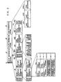
- the data structure of the map data preliminarily stored in the map data storage means 2 includes a header 11 serving as a regional map data identification symbol, a spot information string 12 relating to such spots as the major intersections, a route information string 13 relating to such routes as the national roads and a name information string 14 relating to the various services.
- the spot information string 12 includes a group of prefectural spot information strings for the prefectures belonging to the region concerned, such as, an Aichi Prefecture spot information string 15 relating to Aichi Prefecture and each of the prefectural spot information strings in the group, e.g., the Aichi Prefecture spot information string 15 includes a group of city spot information strings for the cities belonging to the prefecture concerned, such as, a Nagoya City spot information string 16.
- Each of the city spot information strings in the group e.g., the Nagoya City spot information string 16 includes a spot information group including spot information 171, 172,-for the major spots belonging to Nagoya City and each of the spot information 171, 172,-includes such information as the spot number, spot level, spot named/unnamed and X and Y components of geographical coordinates of the spot concerned.
- the spot named/unnamed includes data indicative of presence or absence of a spot name and in the presence of the spot name a name address indicative of a name information having data for display of the spot name (for example, Nagoya Station). Unnamed spots are used only for forming a route.
- the route information string 13 includes 1st to N route information strings 181, 182,-,18N and pointers 191, 192,-, 19N corresponding in one-to-one relation to the former and each of the spot information strings 181, 182,-, 18N, includes the route number, route level, route classification, group of spot numbers for the spots constituting the route and route end.
- the name information string 14 includes a name information 201, a name information 202,-, a name information 20M.
- the pointer as shown in Figure 2 includes a top address of respective information strings and a name address indicating the name information corresponding to the information string.
- the route classification indicates the type of the route concerned, such as, the national road, express-way, ordinary road, railway or seaside
- the spot classification indicates the type of the spot in question, such as, the ordinary intersection, public highway grade separation, interchange, intersection of public highway and expressway or intersection of public highway and railway.
- the control unit 10 receives the command signal from the control panel 7, the heading signal from the heading sensor 8, the distance signal from the distance sensor 9 and the map data from the map data storage means 2 so that the required processing as will be described later with reference to Figure 5 is executed and the desired display control is performed on the display means 1 thereby supplying video signals to-the display means 1.
- the display means 1 uses a CRT (cathode ray tube) and it displays a map, etc., on the screen in accordance with the video signals from the control unit 10.
- CTR cathode ray tube
- the map corresponding for example to the size 3 being displayed currently if the thin key is operated once, instead of the spots and routes which have had any of the levels 0, 1, 2 and 3 and have therefore been made displayable, those routes and spots having any of the levels 0, 1 and 2 are made displayable and thus the routes and spots having the level 3 are excluded from the displayable ones thereby making the displayed map sparse. That is, the density of features displayed on the map is increased.
- the map having the selected size 3 being displayed, if the dense key is operated once, the spots and routes having the level 4 are additionally made displayable and the displayed map is made dense. That is, the density of features displayed on the map is increased.
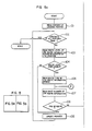
- a step 101 is performed first to read the contents of the leading pointer 191 of the route information string 13 in the map data storage means 2.
- a step 102 is performed to determine whether the contents of all the pointers have been readout.
- the route level information of the ith route information string (the first route information string 181) designated by the ith pointer (the leading pointer 191 at this time) is read out.
- the route level information may be considered as a relative importance assigned to each route.
- a step 104 is performed to determine whether the route level is a display enable one, that is, whether the ith route (the first route) possess an importance which makes it displayable with respect to the size selected in the above-mentioned manner.
- a step 105 is performed so that the pointer is updated, that is, the contents of the next pointer (the second pointer 192) is read out and a return is made to the step 102.
- a step 106 is performed thus reading the route type information of the ith route information string (the first route information string 181).
- a step 107 is performed so that the spot number information (the leading spot number information at this time) of the ith route information string (the first route information string 181) is read out.
- a step 108 is performed to determine whether the end of route information of the ith route information string (the first route information string 181) has been read out.
- the spot level information assigned to that spot number of the spot information string 12 corresponding to the spot number concerned (the leading spot number) is read out and a decision is made as to whether the spot number concerned has an importance which makes it displayable with respect to the size selected in the above-mentioned way.
- this spot is one which needs not be displayed, a return is made to the step 107 so that the next spot number of the ith route information string (the first route information string 181) is read out.
- a step 110 is performed to determine whether the spot is of the spot number extracted for the first time for the ith route information string (the first route information string 181).
- the decision rssults in YES and then steps 111 to 114 are performed.
- the geographical coordinate X and Y components of the spot are read out so that the geographical coordinates (X,Y) are converted to display coordinates (X 1 ,Y 1 ) and then an area A to which the display coordinates (X 1 ,Y 1 ) belong is determined.
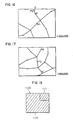
- This coordinate conversion processing is such that, as shown in Figure 6a showing the geographical coordinate system and Figure 6b showing the display coordinate system, (1) the point (MPOS, BPOS) is obtained which corresponds to the geographical coordinates of the geographical coordinate system having one-to-one correspondence to the origin (0,0) of the hatched area of the display coordinate system (corresponding to the map display area of the display means (1), and then (2) in accordance with the obtained point (MPOS, BPOS) the geographical coordinates (LPOS, APOS) of the spot in question are converted to the corresponding spot (X 1 ,Y 1 ) of the display coordinate system.
- the point (MPOS, BPOS) is obtained which corresponds to the geographical coordinates of the geographical coordinate system having one-to-one correspondence to the origin (0,0) of the hatched area of the display coordinate system (corresponding to the map display area of the display means (1)
- the geographical coordinates (LPOS, APOS) of the spot in question are converted to the corresponding spot (X 1 ,Y 1 ) of the display coordinate system.
- the spot (MPOS, BPOS) is obtained in the following way. Firstly, the present position or the center point of an administrative division spot group in the case of an administrative division selection, is determined as the displayed map center coordinates (MAPCENX, MAPCENY) of the geographical coordinate system and then the point (MPOS, BPOS) is obtained from the following equations using as parameters the coordinate information MAPCENX and MAPCENY, the numbers of dots a and b of the map display screen of the display means 1 ( Figure 8) and the number of dots LDOT per unit longitude and the number of dots ADOT per unit latitude which are determined in accordance with the selected size;
- the coordinate of the present position is referred as (MAPCENX, MAPCENY).
- the above-mentioned area determination processing is performed by determining that the display coordinate point (X 1 ,Y 1 ) obtained by the previously mentioned coordinate conversion process belongs to one of the areas 0 to VIII divided as shown in Figure 7a.
- the area IV corresponds to the hatched area shown in Figure 8 or the map display area.
- the step 108 is performed to determine whether the route is ended. If it is not, then the step 109 is performed to determine whether the spot level of this spot number is a display enable level. If it is not, then a return is made to the step 107. If it is the display enable level, then the step 110 is performed to determine whether this spot number is the one extracted for the first time for the ith route information string (the first route information string 181).
- the decision results in NO and then steps 115 to 118 are performed in this order thereby performing a similar process as in the steps 111 to 114.
- the geographical coordinates (X,Y) of this spot number (the jth spot number) are converted to the corresponding display coordinates (X 2 ,Y 2 ) and an area B to which the display coordinates (X 2 ,Y 2 ) belong is determined.
- a step 119 is performed to make a decision as to whether the connection between the point (X 1 ,Y 1 ) and the point (X 2 ,Y 2 ) is to be displayed, that is, whether there is a specified relation between the areas A and B.
- the decision process determines that there is no specified relation (this is indicated by a mark X in Figure 7b).
- steps 120 and 121 are performed so that an area updating process of changing the area A to the area B and a coordinate updating process of changing the coordinates (X 1 ,Y 1 ) to the coordinates (X 2 ,Y 2 ) are performed and a return is made to the step 107.
- a step 122 is performed so that the line connecting the point (X 1 ,Y 1 ) and the point (X 2 ,Y 2 ) is displayed on the display screen in accordance with the type of the route.
- the ith route (the first route) is a national road, the route is displayed with an increased brightness as compared with the other routes.
- the steps 120 and 121 are performed to effect the area updating process and the coordinate updating process and a return is made to the step 107.
- the route including the steps 107, 108 and 109 and the route including the steps 107, 108, 109, 110 and 115 to 122 are selectively performed thus making the required route displays for the ith route (the first route).
- the step 105 is performed and the pointer updating processing is performed.
- the processing for the next route is performed in the like manner as in the case of the first route.
- control unit 10 receives enlargement commands from selecting means, e.g., the control panel 7, those spots having the corresponding levels to the commands are extracted from the routes of the route information strings in the map data storage means 2 which have those levels corresponding to the commands and the extracted spots are subjected to the coordinate conversion thus determining the presence of a specified relation between the adjacent spots and thereby displaying the connection between the spots having the specified relation with a brightness corresponding to the type of the route.
- the spot information of the map data are provided with geographical coordinates and also the spot numbers are each provided with at least a level, with the result that the selection of any desired display mode by the operator results in the display of maps which have the levels corresponding to the selected display mode thus making it possible to ensure a satisfactory freedom for the display patterns even if the data capacity is relatively small.
- the display means 1 is not limited to a CRT and it may be any other display device such as a crystal liquid display or EL display.
- the map data storage means 2 includes an ROM, it may be also a magnetic tape, magnetic disk, magnetic bubbles or the like. In this case, it is needless to say that a reader must be used to read the map data.
- the heading sensor 8 is of the type which detects the earth's magnetic field it is possible to use a heading sensor of the gyro type which detects the relative direction of movement of a vehicle.
- the present invention embraces cases where the coordinates of each spot are given in terms of the spherical coordinates with respect to a specified spot (e.g., Tokyo) in terms of the rectangular coordinates with respect to the specified spot.
- a specified spot e.g., Tokyo
- FIG. 9 is a block diagram showing the overall construction of the second embodiment of the invention.
- numeral 110 designates a heading detector for detecting the direction of movement of a vehicle, 120 a distance sensor for detecting the distance traveled by the vehicle, 130 a command device operable by the operator to set the present position and destination of the vehicle, 140 an electronic control circuit including a CPU 141, a ROM 142, a RAM 143 and an I/0 circuit section, and 190 a display controller for receiving the signals from the electronic control circuit 140 to display a map on a display means 10.
- the heading detector 110 includes a heading sensor having a ring-shaped permalloy core, an excitation coil and a pair of coils arranged perpendicular to each other to detect the X and Y components of the earth's magnetic field corresponding to the direction of movement of a vehicle in accordance with the output voltages of the coils and A-D converters for converting the analog signals detected by the heading sensor 110 to digital signals thereby generating digital signals indicative of the X and Y components of the earth's magnetic field corresponding to the direction of movement of the vehicle.
- the distance sensor 120 indirectly detects the rotation of the speedometer cable or the rotation of the output shaft of the transmission by a reed switch, magnetic sensitive element or photoelectric conversion element to generate a pulse signal for each unit distance traveled by the vehicle.
- a map data storage means 20 includes a ROM (read only memory) package.
- the data structure of the map data preliminarily stored in the map data storage means 20 is the same with that shown in Figure 2.
- the electronic control circuit 140 receives the map data from the map data storage means 20, the heading signal from the heading detector 110, the distance signal from the distance sensor 120 and the command signal from the command device 130 to execute a processing which will be described later and thereby supply control signals to the display controller 190.
- the display controller 190 is responsive to the control signals from the electronic control circuit 140 to perform display controls for the display means, 10 and supply video signals to the display means 10.
- the display means 10 includes for example a cathode ray tube, liquid crystal display or LED display and it is responsive to the video signals from the display controller 190 to display a road map, a vehicle's present position P and a destination Q as shown in the Figure.
- a navigation key 131 shown in Figure 10 is depressed thus displaying a given number of prefectural names on the display means 10. While looking at the list of the prefectural names on the screen of the display means 10, the vehicle occupant depresses a cursor key 132 or 133 so as to display within a specified area of the screen the name of the prefecture to which the present position of the vehicle belongs, e.g., Aichi Prefecture.
- a cursor key 134 is depressed so that the names of a plurality of cities belonging to Aichi Prefecture are displayed on the screen of the display means 10. While looking at the names of the cities, the occupant depresses the cursor key 132 or 133 so that the name of the city to which the present position of the vehicle belongs, e.g., the name of Kariya City is displayed within the specified screen area.
- the cursor 134 is depressed so that the names of a plurality of towns or the like belonging to Kariya City are displayed on the screen of the display means 10. While looking at the names of the towns, the occupant depresses the cursor key 132 or 133 so that the name of the town to which the vehicle's present position belongs, e.g., the name of Showa Town is displayed within the specified screen area. Then, a set key 136 is depressed so that the map of the whole Showa Town is displayed on the screen of the display means 10.
- the map search as mentioned above is realized by the process shown in Figures 26 to 33.
- the destination is set in the like manner as the setting of the present position of the vehicle, that is, a map to which the destination belongs is first displayed on the screen of the display means 10 and then after he operation of a destination key 138 one of the cursor keys 132 to 135 is operated thus setting a destination mark Q on the displayed map.
- the coordinate of a position of the cursor is memorized after the cursor is moved to the destination when the set key 136 is turned on.
- the map for setting the present position or destination of a vehicle needs not be a town-based map as mentioned previously and it may be a city or prefectural map.
- the map may be one on which the driver or the like desires to set the present position or destination of a vehicle.
- the spot names displayed on the display means 10 may be changed to the greater divisions, e.g., from the town names to the city names and from the city names to the prefectural names.
- the processing of the second embodiment will now be described with reference to the flow chart of Figure 11 showing a control program.
- the control program of Figure 11 shows a routine 1000 which is started after the ignition switch has been turned on and the present position and destination of a vehicle have been set by the operation of the command device 130 as mentioned previously and the routine is executed at intervals of a predetermined period (e.g., at intervals of 100 ms).
- the heading signal from the heading detector 110 is read first at a step 1010 and then the heading of the vehicle with respect to the earth's magnetic field is computed at the next step 1020.
- the distance signal from the distance sensor 120 is detected at a step 1030 and the next step 1040 computes the present position of the vehicle from the vehicle heading computed at the step 1020 and the distance signal detected at the step 1030.
- the present position of the vehicle is determined by computing the distance traveled from the vehicle's present position (starting position) set prior to the starting of the processing of the routine 1000 and the heading of the vehicle.
- the separating distance between the destination already set prior to the starting of the processing of the routine and the present position of the vehicle determined at the step 1040 is computed.
- the distance between the destination and the present position is calculated depending on the coordinates of the destination and the present position.
- the processing transfers to a step 1060 so that a reduced scale b of a map to be displayed on the display means 10 is determined in accordance with the separating distance obtained at the step 1050.
- the next step 1070 determines whether the reduced scale b determined at the step 1060 is equal to the reduced scale a of the map actually displayed on the display means 10. If the decision results in NO, a transfer is made to the next step 1080 where a map on the reduced scale b is displayed on the display means 10 thereby ending the execution of the routine 1000.
- step 1070 determines that the reduced scale a of the actually displayed map is equal to the reduced scale b obtained at the step 1060, the execution of the routine 1000 is ended at this state and the map reduced to the scale a and presently displayed on the display means 10 is displayed continuously.
- the flow chart shown in Figure 12 is a control program showing detailed operations performed at the step 1060, and firstly a step 1061 determines whether the separating distance L obtained at the step 1050 of Figure 11 is less than the separating distance L(-1) obtained previously (100 msec before), that is, whether the vehicle is moving toward the destination.
- the step 1061 determines that the separating distance L is less than the previously computed separating distance L(-1) and the next step 1062 determines whether the separating distance L is 5 Km or over.
- step 1062 determines that the separating distance L is 5 Km or over, a transfer is made to a step 1063 thus determining whether the separating distance L is 20 Km or over.
- step 1062 determines that the separating distance L is less than 5 Km, then the reduced scale b of the map is set to 1/25,000 and a transfer is made to the process of the step 1070 shown in Figure 11.
- step 1063 determines that the separating distance L is 20 Km or over, whether the separating distance L is 50 Km or over is determined at a step which is not shown. If the step 1063 determines that the separating distance L is less than 20 Km, then the map scale b is set to 1/50,000 at a step 1065 and a transfer is made to the process of the step 1070 shown in Figure 11.
- the step 1060 of Figure 11 determines the proper reduced scale b corresponding to the separating distance L as shown in the following Table 1: for example, the reduced scale b is set to 1/25,000 when the separating distance L is not less than 0 Km and not greater than 5 Km and it is set to 1/50,000 when the separating distance L is not less than 5 Km and not greater than 20 Km.
- the step 1061 determines that the separating distance L is greater than the previously computed separating distance L(-1) and a step 1066 determines whether the separating distance L is 6 Km or over.
- step 1066 determines that the separating distance L is under 6 Km
- the map scale b is set to 1/25,000 at the step 1064. If the step 1066 determines that the separating distance L is 6 Km or over, a step 1067 determines whether the separating distance L is 24 Km or over.
- the map scale b is set to 1/50,000 at a step 1067. If the step 1067 determines that the separating distance L is 24 Km or over, whether the separating distance L is 60 Km or over is determined at a step which is not shown.
- the step 1060 of Figure 11 determines the reduced scale b in accordance with the separating distance L as shown in the following Table 2: for example, the reduced scale b is set to 1/25,000 when the separating distance L is from 0 to 6 Km and it is set to 1/50,000 when the separating distance L is from 6 to 24 Km.
- a range of the separating distances L with respect to the map scales b has been predetermined as shown in Table 1 for the case where the vehicle is moving toward the destination, and another range of the separating distances L with respect to the map scales b has been predetermined as shown in Table 2 for the case where the vehicle is moving away from the destination.
- the reason for predetermining the enlarging preset values and the reducing preset values to differ in value as will be seen from the above Tables 1 and 2 is that if the enlarging preset values and the reducing preset values are preset to the same values, when the vehicle is driving on a road where the separating distance L tends to attain a value close to one of the preset values, the map is enlarged or reduced each time the vehicle approaches the destination so that the separating distance L becomes less than the preset value or the vehicle moves away from the destination so that the separating distance L exceeds the preset value thus making the displayed map extremely hard to see for the driver, etc.
- the level information of the map data in the map data storage medium 20 have been predetermined in correspondence to the map scales b as shown in the following Table 3 so that as for example, the level information 0 corresponds to the reduced scale of 1/1,000,000 and the level information 0 and 1 correspond to the reduced scale of 1/500,000.
- the maps displayed on the display means, 10 become as shown in Figures 13 to 15 in accordance with the level information corresponding to the map scales.
- Figure 13 shows the picture on the display means 10 showing the map on a scale of 1/1,000,000 and spots a, to a3 and routes of the level 0 are displayed. Also, a spot Q represents the destination and a spot P, represents the present position of the vehicle.
- the picture on the display means 10 is changed to one as shown in Figure 14 since the map scale is 1/500,000 and the level information are 0 and 1 when 200 Km ⁇ L ⁇ 500 Km as mentioned previously.
- the picture of Figure 14 shows in enlarged form the portion A of Figure 13 centering a middle point R 1 between the spot P 2 and the destination Q. Also, the spot a 1 represents a spot of the level 0 and spots b 1 to b 5 represent spots of the level 1. Of course, the displayed routes have the route information of the levels 0 and 1.
- the map displayed on the display means 10 is enlarged to show greater details as the vehicle comes nearer to the destination.
- the present position of the vehicle changing in response to the movement of the vehicle is computed in accordance with the signals from the heading detector 110 and the distance sensor 120 and one of the plurality of predetermined map scales b is selected in accordance with the separating distance L between the computed present position of the vehicle and the destination. If the selected scale b is different from the scale a of the map actually displayed on the display presently, the process of replacing the displayed map on the display means 10 with one having the reduced scale b is performed.
- the maps of the selected scales b are displayed by selecting the proper routes of the preset levels corresponding to the selected scales b from the route information strings stored in the map data storage means 20, extracting the spots of the preset levels from the routes, performing the coordinate conversion on the extracted spots and displaying the connections between the adjacent spots having a specified relation with a brightness corresponding to the route type.
- the method of selecting the proper spot names or spot numbers may be used as the command method for establishing the present position and destination of a vehicle.
- any point on the line connecting the present position and destination of the vehicle or the present position of the vehicle may be used as the center of the map.
- Figure 16 shows a map which is on a reduced scale of 1/200,000 in correspondence to the separating distance Land not including the destination.
- symbol P 1 ' designates the present position of the vehicle and symbol Q designates the destination. Since the destination Q is not included in the map displayed, the destination Q is displayed at one end of the display screen thus indicating the direction of the destination.
- the map becomes as shown in Figure 17 and the displayed map includes the destination Q. In this case, the same effect as the previously mentioned embodiment is also obtained.
- Figure 18 shows display means 1100 including a sub-display area 1111 and a main display area 1112.
- Figure 19 is a block diagram showing the overall construction of the third embodiment, in which numeral 1110 desginates a CRT display serving as the display means, 1300 a map data storage means of the same type as shown in the first and second embodiment, 1500 a manual control panel, 1700 an electronic control unit serving as control means and including a microcomputer having a CPU 1719, a ROM 1721, a RAM 1723 and an I/0 device 1725 and a display controller 1727.
- CPU 1719 describes the code indicating that RAM 1723 is backed up when the unit 1700 is first supplied with power.
- Numeral 2900 designates a heading sensor for detecting the direction of movement of a vehicle or the direction of the earth's magnetic field with respect to the vehicle, and 3100 a distance sensor for detecting the distance traveled by the vehicle.
- the manual control panel 1500 includes at least an auto key 1533, a selection key 1535, a reservation key 1537, a map search key 1539, a name search key 1541, a set key 1543, an upward move cursor key 1545, a downward move cursor key 1547, a left move cursor key 1549 and a right move cursor key 1551 and the depression of each of these keys 1533, 1535, 1537, 1539, 1541, 1543, 1545, 1547, 1549 and 1551 supplies the corresponding command signal to the electronic control unit 1700.
- a step 2101 determines whether the memories (RAM) have been backed up properly on the basis of the code of the RAM 1723 described in the CPU 1729. If it is, then a step 2102 is performed so that the picture data which have already been stored in the RAM 1723, that is, the data relating to the map which was being displayed on the CRT display means 1100 at the time that the ignition switch was turned off lately, are read from the RAM 1723 and the map is displayed on the map display area 1110 of of the CRT display means 1100 and the processing is ended.
- a step 2103 is performed in place of the step 2102 so that a process is performed to display a general map on the main display area 1112 of the CRT display means 1100 and the processing is ended.
- the reduced scale required for displaying the general map on the main display area 1112 is selected and the coordinate conversion from the geographical coordinates (X,Y) to the display coordinates (x,y) is effected in accordance with the scale.
- a present position mark displayed by superimposition on the map displayed by the step 2102 or 2103 has been moved and arranged at the present position on the displayed map through the operation of the cursor keys 1545 to 1551
- the set key 1543 is turned on so that the execution of the processing shown in Figure 22 is started and a step 2201 performs a process of displaying a new map centering the present position on the main display area 1112.
- a step 2202 performs a process of displaying an enlarged map centering the present position on the sub-display area 1111 and the processing shown in Figure 22 is ended.
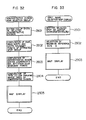
- the new map display process and the enlarged map display process performed at the steps 2201 and 2202, respectively, are as shown by the flow chart of Figure 28 and a step 2301 is performed first to read the contents of the leading address in the route information string of the map data in the ROM package 1300. Then, a step 2302 is performed to determine whether the contents of all the addresses have been read. Since this is just after the reading of the contents of the leading address, the decision results in NO and then a step 2303 is performed. At the step 2303, the route level information of the ith route information string (the first route information string) desginated by the ith address (the leading address at this time) is read out.
- the route level information may be considered as a relative importance assigned to each route.
- a step 2304 is performed to determine whether the route level is a display enable one, that is, whether the ith route (the first route) has an importance which enables its display with respect to the selected size. If the ith route (the first route) needs not be displayed, a step 2305 is performed so that the address is updated, that is, the contents of the next address (the second address) is read out and a return is made to the step 2302. If the ith route (the first route) is to be displayed, then a step 2306 is performed to read the spot number information (the leading spot number information at this time) of the ith route information string (the first route information string).
- a step 2307 is performed to determine whether the end of route information of the ith route information string (the first route information string) has been read out. Since this occurs just after the reading of the leading spot number information, the decision results in NO and then a step 2308 is performed thus reading the spot level information assigned to the spot number of the spot information string corresponding to the spot number concerned (the leading spot number) and thereby determining whether the spot number has an importance which enables its display with respect to the selected size. If this spot is one which needs not be displayed, a return is made to the step 2306 so that the next spot number of the ith route information string (the first route information string) is read out.
- a step 2309 is performed to determine whether the spot is the one extracted for the first time for the ith route information string (the first route information string). Since this is the first spot number thus far, the decision results in YES and steps 2310 to 2313 are performed.
- the geographical coordinate X and Y components of the spot are read out and the coordinate point (X,Y) is then converted to a display coordinate point ( X1 ,v 1 ) thereby determining an area A to which the display coordinate point (x i ,y i ) belongs.
- this coordinate conversion process is effected in such a manner that (1) the point (MPOS, BPOS) is determined which corresponds to the coordinates (X,Y) of the geographical coordinate system having one-to-one correspondence to the origin (0,0) of the hatched area of the display coordinate system (corresponding to the main display area 1112 or the sub-display area 1111 of the CRT display means 1100) and then (2) in accordance with the thus determined point (MPOS, BPOS) the coordinates (LPOS, APOS) of the spot in question are converted to the point (x 1 ,y 1 ) of the display coordinate system.
- the point (MPOS, BPOS) is determined in the following manner.
- the present position is first determined as the displayed map center coordinates (MAPCENX, MAPCENY) on the map coordinate system and the point (MPOS, BPOS) is obtained from the following equations using as parameters the coordinate information MAPCENX and MAPCENY, the numbers of dots a and b in the map display area 1110 of the CRT display means 1100 ( Figure 8) and the number of dots LOOT per unit longitude and the number of dots ADOT per unit latitude which are determined according to the selected size: Then, the point (x 1 ,y 1 ) is obtained from the following equations
- the area determining process is effected by determining whether the display coordinate point (x1N1) obtained by the previously mentioned coordinate conversion process belongs to the main display area 1112 or the sub-display area 1111.
- the area A of the display coordinate point (x 1 ,y 1 ) is determined at the step 2313 as described at the step 114 shown in Figure 5b, a return is made to the step 2306 and the next spot number of the ith route information string (the first route information string) is read out. Then, the step 2307 is performed to determine whether the end of route information has been read out. If it is not, the step 2308 is performed to determine whether the spot level of the spot number is a display enable one. If it is not, a return is made to the step 2306.
- the step 2309 is performed to determine whether the spot number is the one extracted for the first time for the ith route information string (the first route information string). Since the first spot number has already been extracted by this time, the decision result is NO and then steps 2314 to 2317 are performed successively thus perfoming a similar process as the steps 2310 to 2313. More specifically, the spot coordinates (X,Y) of the spot number (the jth spot number) are converted to the corresponding display coordinates (x 2 ,y,) and an area B of the display coordinates ( X2 , Y2 ) is obtained.
- a step 2318 is performed to determine whether the connection between the point (x " y,) and the point ( X2 , Yl ) is to be displayed, that is, whether the areas A and B are both the main display area 1112 or the sub-display area 1111. If at least one of the areas A and B is not the main display area 1112 or the sub-display area 1111, then steps 2319 and 2320 are performed thus effecting an area updating process for changing the area B to the area A and a coordinate updating process for changing the coordinates ( X2 , Y2 ) to the coordinates (x,,v,) and thereby making a return to the step 2306.
- a step 2321 is performed so that the connection between the point (x i ,y i ) and the point ( X2 , Y2 ) is displayed on the display screen. Then, the steps 2319 and 2320 are performed so that the area updating process and the coordinate updating process are performed and a return is made to the step 2306. Thereafter, the route including the steps 2306, 2307 and 2308 and the route including the steps 2306, 2307, 2308, 2309 and 2314 to 2321 (the step 2321 is eliminated as occasion demands) are selectively performed thus making route displays until the end of route for the ith route (the first route) is read.
- the step 2307 when the end of the route for the ith route (the first route) is read out, the result of the decision of the step 2307 changes to YES and then the step 2305 is performed thereby performing an address updating process.
- the processing of the next route (the second route) is performed in the like manner as the processing of the first route.
- the similar processing is successively performed on each of the route information strings so that when the processing of the Nth route information string is completed, the step 2302 determines that the contents of all the addresses have been read out and the map display processing is ended.
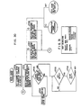
- a step 2401 When the name search key 1541 of the manual control panel 1500 is turned on, the execution of the processing shown in Figure 24 is started and a step 2401 first performs a process of displaying such a message as shown in Figure 25 on the display area of the CRT display means 1100. Then, a prefectural name processing as shown in Figure 26 is performed. In this prefectural name processing, a step 2501 is performed first and the leading prefecture address is set in the pointer. Then, a step 2502 is performed so that the administrative division name information is read from the precectural information and this name and the cursor are displayed altogether on the screen of the CRT display means 1100.
- a step 2503 is performed to determine whether a predetermined number (the total number of prefectures which can be displayed by the map data) of prefectural names have been displayed. If the predetermined number of prefectural names have not been displayed as yet, then a step 2504 is performed so that the prefectural name of the next address is read out and displayed on the CRT display means 1100. When the predetermined number of prefectural names have been displayed on the CRT display means 1100 in this way, the result of the decision of the step 2503 changes to YES and then a step 2505 is performed. At the step 2505, a decision is made as to whether there is any key input from the manual control panel 1500.
- a step 2506 is performed to determine whether the operated key is the upward move cursor key 1545 for moving the cursor position upward, the downward move cursor key 1547 for moving the cursor position downward, the left move cursor key 1549 for moving the cursor position to the left, the set key 1543 for displaying a map or any other key operated by mistake. If it is the upward move cursor key 1545, then a step 2507 is performed to newly set in the pointer the prefectural address which corresponds to the prefecture following the name of the prefecture corresponding to the present cursor position and a return is made to the step 2502.
- a step 2508 is performed to set in the pointer the prefectural information address of the prefecture which had previously corresponded to the cursor position and a return is made to the step 2502. If it is the left move cursor key 1549, then a municipalities process is started. On the other hand, if it is the set key 1543, then an administrative division name selection map display which will be described later with reference to Figure 22 is performed. Thus, in accordance with the prefectural name processing the names of the prefectures belonging to the whole map displayed by the map data storage means 1300 are displayed on the CRT display means 1100 and also the cursor is displayed.
- steps 2601 to 2608 respectively correspond to the steps 2501 to 2508 of the prefectural name processing shown in Figure 26.
- the cursor position corresponds for example to Aichi Prefecture during the execution of the prefectural name processing
- the left move cursor key 1545 is operated, the names of the municipalities belonging to Aichi Prefecture are displayed.
- the right move cursor key 1531 is operated, then the previously mentioned prefectural name processing is started again.
- the left move cursor key 1549 is operated, a spot name
- FIG 30 shows a flow chart of the spot name processing.
- steps 2701 to 2708 respectively correspond to the steps 2501 to 2508 of Figure 26.
- the top address of the name information of the pointer mentioned earlier causes the name to be displayed by using the data of the name information corresponding to the top address.
- the cursor position corresponds for example to Nagoya City as shown in Figure 29
- the operation of the left move cursor key 1549 causes the display pattern on the CRT display means 1100 to change as shown in Figure 31.
- a spot name selection map display processing is performed as will be described later with reference to Figure 33.
- an administrative division name selection map display processing as shown in Figure 32 is started.
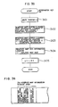
- a step 2801 is performed first to extract the spot information of the spots belonging to the selected administrative division.
- a step 2802 is performed to compute the four boundary points or the four points of the extracted spots which are respectively positioned at the eastern, western, northern and southern ends.
- a step 2803 is performed so that the coordinates (MX, MY) of the center point of the administrative division are obtained from the four boundary points.
- a step 2804 is performed to compute the size required to permit the display of the whole area of the administrative division.
- a step 2805 is performed so that the map of the administrative division is displayed on the CRT display means 1100.
- This map display processing is the same as described in connection with Figure 23.
- the spot name selection map display processing as shown in Figure 33 is started.
- a step 2901 is performed first to set the selected spot as the center coordinates (Mx,My).
- a step 2902 is performed to select a maximum reference size S which can be displayed centering the selected spot on the CRT display means 1100.
- a step 2903 is performed so that a map corresponding to the selected scale S is displayed.
- This map display processing is the same as described in connection with Figure 23.
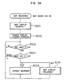
- a map search processing as shown in Figure 34 is started.
- a step 3001 is performed first to make a map display of the whole map area which can be displayed on the CRT display means 1100 in accordance with the map data in the ROM package 1300.
- a step 3002 is performed so that the cursor is displayed at the center position of the map displayed.
- a step 3003 is performed to determine whether there is any key input from the manual control panel 1500. If it is, a step 3004 is performed so as to determine the inputting key.
- a step 3005 is performed so that the cursor is moved in accordance with the operated cursor key.
- a step 3006 is performed so that an enlarged map is now displayed.
- a processing as shown in Figure 35 is started.
- a step 3101 is performed first so that the contents of a write pointer for addressing the reserved map information storage area of the RAM 1723 is set to j.
- a step 3102 is performed so that the X coordinate information of the center of the presently displayed map is written in the jth reserved map center X coordinate information storage location in the jth reserved map information storage area.
- a step 3103 is performed so that the Y coordinate information of the said center is written in the reserved map center Y coordinate information storage location of the jth reserved map information storage location of the jth reserved map information storage area.
- a step 3104 is performed so that displayed map size information is written in the reserved map information storage area.
- a step 3105 is performed so that the content of j is incremented.
- a processing of Figure 35 is ended.
- the information as shown in Figure 36 is stored in the jth reserved map information storage area.
- the processing of Figure 35 is performed and a reservation is made on the desired map.
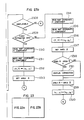
- FIG 37 shows the processing which is started each time the selection key 1535 is turned on.
- a step 3200 is performed first to determine whether the map display system is in an automatic mode, that is, whether an enlarged map centering the present position is currently displayed on the sub-display area 1111. If it is so determined, then a step 3202 is performed so that the enlarged map displayed on the sub-display area 1111 is erased after the step 3201 which is performed so that the automatic mode is off. Then, a step 3203 is performed to read the kth reserved map information designated by the display pointer as shown in Figure 38, for example. Then, a step 3204 is performed so that the new map or the kth reserved map is displayed on the sub-display area 1111 and this processing is ended.
- a step 3205 is performed to determine whether the value of k is (j-1) or greater (where j corresponds to the number of the reserved map information storage area designated by the write pointer as shown in Figure 38). If it is not, then a step 3206 is performed so that the value of k is incremented first and the steps 3203 and 3204 are successively performed thus ending the processing. On the contrary, if the step 3205 determines that k?(j-1 then a step 3207 is performed so that the value of k is set to 1 first and the steps 3203 and 3204 are successively performed thus ending the processing.
- the map display system is in the automatic mode at the time the selection key 1535 is turned on, the presently displayed enlarged map centering the present position is erased and instead the reserved map is displayed. On the contrary, if the map display system is not in the automatic mode at the time the selection key 1535 is turned on, the next reserved map is displayed.
- FIG 39 shows the processing which is started each time the auto key 1533 is turned on.
- a step 3301 is performed first to determine whether the map display system is presently in the automatic mode. If it is, the processing is ended without performing any operation. On the contrary, if it is not, then a step 3302 is performed so that the reserved map presently displayed on the sub-display area 1111 is erased. Then, a step 3303 is performed so that the present position on the map displayed on the main display area 1112 is set as the center of the sub-display area 1111.
- the step 3304 is performed so that the size of the map displayed on the main display area 1112 is multiplied by a (a is greater than 1) and the size of a map to be displayed on the sub-display area 1111 is determined.
- a step 3305 is performed thus displaying on the sub-display area 1111 a map which centers the present position and is enlarged to the new size obtained by multiplying the size of the main display map by a.
- a step 3306 is performed so that the automatic mode is on and the processing is ended.
- a processing is performed so that an enlarged map centering the present position of the vehicle at that point is displayed anew.
- This map display processing is similar to the above-mentioned enlarged map display processing.
- the decision can be made by making a comparison between the display coordinates of the sub-display area 1111 corresponding to the map display selection limit and the display coordinates of the vehicle's present position on the sub-display area 1111 and thereby determining whether the present position of the vehicle has reached the map display selection limit.
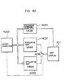
- FIG 40 is a block diagram showing schematically a modification of the third embodiment of the invention.
- numeral 4053 designates a microcomputer
- 4055 a video RAM (VRAM) used exclusively to store the data for displaying messages, marks, etc., on a CRT display means 4011
- 4057 a video RAM (VRAM) for storing the picture data of maps to be displayed on the CRT display means (4011, 4059 an exclusive map video RAM (VRAM) used in the like manner as the exclusive map VRAM 4057
- VRAM exclusive map video RAM
- switch means for switching the connections between the CRT display means 4011 and the exclusive map VRAMs 4057 and 4059, respectively.
- This embodiment is operable in two display modes, i.e., a VRAM 1 display mode and VRAM 2 display mode.
- the switch means 4061 in the VRAM 1 display mode, the switch means 4061 is in the position shown and thus the map data from the exclusive map VRAM 4057 is sent to the CRT display means 4011 thereby displaying the main display map on the screen of the CRT display means 4011.
- change map data is written in the other exclusive map VRAM 4059 so that upon completion of the writing the switch means 4061 changes its position and the change map is displayed on the sub-display area of the CRT display means 4011.
- the map data from the exclusive map VRAM 4059 is sent to the CRT display means 4011 and a map is displayed on the main display area of the CRT display means 4011.
- change map data is written in the exclusive map VRAM 4057 so that upon completion of the writing the switch means 4061 is returned to the illustrated position and a change map is displayed on the sub-display area of the CRT display means 4011.
- VRAM 4055 is one which displays function messages, marks such as present position and destination and travel paths, and the VRAM 4055 is always connected to the CRT display means 4011 so as to superimpose a message, marks or the like on the map displayed on the CRT display means 4011. Since the present embodiment includes the two exclusive map VRAMs which are switched to alternately display a map on the CRT display means 4011, it is possible to reduce the required map displaying time.
Description
- The present invention relates to a map display system including display means for displaying a map, map data storage means for storing at least spot coordinate data to provide a coordinate spot relative to a predetermined coordinate origin spot, extraction means for extracting from said map data storage means the spot coordinate data indicative of the spot located to be displayed by said display means, and display control means responsive to the spot coordinate data of each spot extracted by said extraction means for forming display data which are provided to said display means to display a map with a variable scale.
- Recently, systems have been developed in which a map is displayed to direct the movement of a vehicle such as an automobile. This type of map display system has been usually provided with separate map data for each map to be displayed and therefore it tends to give rise to disadvantages that in order to ensure a wide setting of the area of each map to be displayed while retaining their details and that the displayed map may for example be enlarged or reduced as occasion demands thus providing a freedom of display pattern, the capacity of the map data as a whole will be increased with a resulting increase in the capacity of the map data storage means, while on the other hand a limitation to the map data capacity tends to reduce the area on the whole of each map to be displayed or cause the displayed map to lose its details.
- Thus from GB-A-2 100 001 a road map display system for an automotive vehicle is known, comprising a first memory for storing road map data defined on first coordinates of a map, a scale selector for varying a scale of the map, a transforming unit responsive to the scale selector for transforming the map data of the first memory into map data defined on second coordinates, a second memory for storing the transformed map data, and a display unit for displaying the road map which is expanded or contracted depending on the selected map scale.
- Furthermore from EP-A-0 066 877 a navigator for automotive vehicles is known, comprising display means, memory means for storing map data to display a particular road map on the display means and other map data to display related road maps thereon with a different scale from that of the particular road map, alternation means for alternating the scale of a road map, and control means for reading the map data indicative of the particular road map and the other map data indicative of the related road maps from the memory means.
- Although it is desirable that the displayed map is automatically enlarged as a vehicle comes near to its destination and contrary the displayed map is automatically reduced as the vehicle moves far away from the destination, such known map display systems for vehicles have a limit to the display patterns of maps to be dispalyed and thus are incapable of changing the displayed map in accordance with the separating distance between the present position of a vehicle and its destination.
- This type of known systems is also so designed that only a single map is displayed on the map display area of display means and thus the display system tends to give rise to disadvantages that in order that the present position of a vehicle may be recognized as a spot on a wide map as well as a spot on a map which is a detailed one but showing a limited area in the vicinity of the present position of the vehicle, it is necessary to provide a plurality of map patterns drawn on different reduced scales and covering the same spot thus inevitably increasing the required data storage capacity.
- With a view to overcoming the above referenced deficiencies of this prior art, it is an object of the invention to provide a map display system enabling enlargement of the area of each map to be displayed and a reduction in the required map data capacity while being able to automatically displaying on a display means a map with a variable scale corresponding to the separating distance between the present position of a vehicle and its destination thus serving as a readily usable road guide to the driver.
- To accomplish this object of the invention, there is provided a map display system of the above mentioned type comprising map data storage means for storing, in addition to spot coordinate data, spot level data indicative of each spot relative to all of said spots constituting the map and indicative of the level corresponding to the importance of the spot. Designation means is provided to designate at least one of said various scales of the map or a density of features to be displayed on the map while said extraction means is responsive to the scale or the density designated by the designation means to extract from the map data storage means the spot coordinate data of the spot having the spot level data of importance relative to the scale or the density.
- The present invention will be apparent from the following detailed description taken in conjunction with the accompanying drawings, in which:
-
- Figure 1 is a block diagram showing a first embodiment of the invention;
- Figure 2 is a diagram showing a map data structure according to the invention;
- Figures 3a to 3c are diagrams showing display patterns used in the case where a display mode is a reduction mode;
- Figures 4a to 4c are diagrams showing other display patterns used in the case where the display mode is a dense mode;
- Figure 5 is a flow chart for explaining the processing operations according to the invention;
- Figures 6a and 6b are diagrams for explaining the coordinate conversion from a geographical coordinate system to a display coordinate system;
- Figures 7a and 7b are diagrams for explaining the connection conditions between the points on the display coordinate system;
- Figure 8 is a diagram for explaining the method of obtaining the geographical coordinates (MPOS, BPOS) corresponding to the origin (0,0) on a map display screen;
- Figure 9 is a block diagram showing the simplified construction of a second embodiment of the invention;
- Figure 10 is a diagram showing the arrangement of principal keys in the command device of Figure 10;
- Figure 11 is a flow chart showing a control program for the second embodiment;
- Figure 12 is a flow chart showing the processing of the
step 1060 in Figure 11; - Figures 13 to 15 are diagrams showing display patterns displayed on the display means in accordance with the second embodiment;
- Figures 16 and 17 are diagrams showing other display patterns displayed on the display means in accordance with the second embodiment;
- Figure 18 is a diagram showing an example of display areas according to a third embodiment of the invention;
- Figure 19 is a block diagram showing the overall construction of the third embodiment;
- Figure 20 is a diagram showing an example of the arrangement of operating keys on a control panel;
- Figure 21 is a flow chart showing the processing executed when an ignition switch is turned on;
- Figure 22 is a flow chart executed when a set key is turned on;
- Figure 23 is a flow chart showing the map display processing;
- Figure 24 is a flow chart showing the processing executed when a name search key is turned on;
- Figure 25 is a diagram showing a display pattern on a CRT display means made when the searching message display processing of Figure 24 is performed.
- Figure 26 is a flow chart showing the prefectural name processing of Figure 24;
- Figure 27 is a diagram showing a display pattern made on the CRT display means when the prefectural name processing of Figure 26 is performed;
- Figure 28 is a flow chart showing the municipalities name processing of the prefectural name processing;
- Figure 29 is a diagram showing a display pattern made on the CRT display means when the municipalities name processing is performed;
- Figure 30 is a flow chart showing a spot name processing of the municipalities name processing;
- Figure 31 is a diagram showing a display pattern made on the CRT display means when the spot name processing is performed;
- Figure 32 is a flow chart showing an administrative division name selection map display processing of the municipalities name processing;
- Figure 33 is a flow chart showing a spot name selection map display processing of the spot name processing;
- Figure 34 is a flow chart showing the processing performed when a map search key is turned on;
- Figure 35 is a flow chart showing the processing performed when a reservation key is turned on;
- Figure 36 is a diagram showing the arrangement of data stored in the jth reserved map information storage area by the processing of Figure 35;
- Figure 37 is a flow chart showing the processing performed when a selection key is turned on;
- Figure 38 is a diagram showing the relationship between the reserved map storage area and a display pointer and a write pointer;
- Figure 39 is a flow chart showing the processing performed when an auto key is turned on; and
- Figure 40 is a block diagram showing the construction of still another embodiment of the invention.
- A first embodiment of the invention will now be described with reference to Figures 1 to 8. Figure 1 is a block diagram of the first embodiment of the invention. In the Figure,
numeral 7 designates a control panel which functions as selection means and is operated by the driver or the like upon operating a travel guidance system. Numeral 8 designates a heading sensor for detecting the direction of movement of the vehicle or the direction of the earth's magnetic field with respect to the vehicle, 9 a distance sensor for detecting the distance traveled by the vehicle, 2 a map data storage means preliminarily storing given map data, 10 a control unit comprising a microcomputer 11 including a CPU, a ROM, a RAM and an I/O device and adisplay controller 12 and functionally adapted to perform computational operations and display controls, and 1 a display means adapted to display at least a map. - The
control panel 7 includes an enlargement key for commanding the charge of the map being displayed or the presently displayed map to a higher magnification, a reduction key for changing the presently displayed map to a lower reduced scale, a thin key for changing the presently displayed map to a lower density, and a dense key for changing the presently displayed map to a higher density. - The
heading sensor 8 includes a ring-shaped permalloy core, an excitation coil and two coils arranged perpendicular to each other and it supplies to the control unit 10 a heading signal for detecting the direction of movement of the vehicle with respect to the earth's magnetic field in accordance with the output voltages of the two coils. - The
distance sensor 9 indirectly detects the rotation of the speedometer cable as an electric signal by a reed switch, a magnetic sensitive element or a photoelectric conversion element or detects the rotation of the output shaft of the transmission as an electric signal by similar means as mentioned previously and supplies to the control unit 10 a distance signal which is used in the computation of the distance traveled by the vehicle. - The map data storage means 2 includes a ROM (read only memory) package. As shown in Figure 2, for example, the data structure of the map data preliminarily stored in the map data storage means 2 includes a header 11 serving as a regional map data identification symbol, a
spot information string 12 relating to such spots as the major intersections, aroute information string 13 relating to such routes as the national roads and aname information string 14 relating to the various services. Thespot information string 12 includes a group of prefectural spot information strings for the prefectures belonging to the region concerned, such as, an Aichi Prefecturespot information string 15 relating to Aichi Prefecture and each of the prefectural spot information strings in the group, e.g., the Aichi Prefecturespot information string 15 includes a group of city spot information strings for the cities belonging to the prefecture concerned, such as, a Nagoya Cityspot information string 16. Each of the city spot information strings in the group, e.g., the Nagoya Cityspot information string 16 includes a spot information group includingspot information spot information route information string 13 includes 1st to Nroute information strings pointers spot information strings name information string 14 includes aname information 201, aname information 202,-, aname information 20M. The pointer as shown in Figure 2 includes a top address of respective information strings and a name address indicating the name information corresponding to the information string. - The route classification indicates the type of the route concerned, such as, the national road, express-way, ordinary road, railway or seaside, and the spot classification indicates the type of the spot in question, such as, the ordinary intersection, public highway grade separation, interchange, intersection of public highway and expressway or intersection of public highway and railway.
- The
control unit 10 receives the command signal from thecontrol panel 7, the heading signal from the headingsensor 8, the distance signal from thedistance sensor 9 and the map data from the map data storage means 2 so that the required processing as will be described later with reference to Figure 5 is executed and the desired display control is performed on the display means 1 thereby supplying video signals to-the display means 1. - The display means 1 uses a CRT (cathode ray tube) and it displays a map, etc., on the screen in accordance with the video signals from the
control unit 10. - With the construction described above, the relationship between the level information of the map data in the map data storage means 2 and the sizes selectable by the operation of the keys becomes as shown in the following Table I.

- More specifically, when the size 0 corresponding to the scale of 1/1,000,000 is selected by the operation of the enlargement key or the reduction key, only those routes and spots having the predetermined level information of 0 are enabled for display on the display means 1. On the other hand, when the
size 1 corresponding to the scale of 1/500,000 is selected, only those routes and spots having the level information of 0 or 1 are made displayable and the same is applicable to the relationship between the selection of the other sizes and the corresponding objects to be displayed. - While the relationship between the sizes and the levels usually becomes as indicated in the above Table I, when the thin key or the dense key is operated, the relationship between the two is updated as shown in the following Table II or III each time the thin key or the dense key is operated. The Table II corresponds to the relationship obtained when the thin key is operated once.


- More specifically, with the map corresponding for example to the
size 3 being displayed currently, if the thin key is operated once, instead of the spots and routes which have had any of thelevels levels level 3 are excluded from the displayable ones thereby making the displayed map sparse. That is, the density of features displayed on the map is increased. On the other hand, with the map having the selectedsize 3 being displayed, if the dense key is operated once, the spots and routes having thelevel 4 are additionally made displayable and the displayed map is made dense. That is, the density of features displayed on the map is increased. - Next, changes of the display pattern on the display means 1 will be explained by way of examples with reference to Figure 3a to 3c and Figures 4a to 4c.
- When the enlargement of the displayed map is commanded by a key operation of the operator or as a result of the internal processing of the
control unit 10, assuming for example, that the displayed map is as shown in Figure 3a, thecontrol unit 10 performs an enlarging process on an area A enclosed by the broken line in Figure 3a and thus the map on the screen of the display means 1 is changed to a relatively detailed one as shown in Figure 3b. Then, if a further enlargement is commanded, the enlarging process is now performed on an area B enclosed by the broken line in Figure 3b and therefore a more detailed map is displayed on the screen of the display means 1 as shown in Figure 3c. Note that points a and b of Figure 3a indicate the same spots as points and b in Figure 3b and the points a to h of Figure 3b represent the same spots as points a to h in Figure 3c. - On the other hand, when commands are given to reduce the displayed map, changes take place which are reverse to those occurring in the display pattern as the result of the above-mentioned enlarging processing. In other words, the displayed map shown in Figure 3c is changed to the displayed map of Figure 3b and then to the displayed map of Figure 3a.
- Also, when a command for making the displayed map dense is generated by a key operation of the operator or as a result of the internal processing of the
control unit 10, assuming for example that the map displayed presently is as shown in Figure 4a, then thecontrol unit 10 performs a densifying process and thus a relatively detailed map as shown in Figure 4b, for example, is displayed on the screen of the display means 1. Then, if a further densification is commanded, a further densifying process is performed and therefore a more detailed map is displayed as shown in Figure 4c, for example. Note that points a' to g' of Figure 4a show the same spots as points a' to g' in Figure 4b and the points a' to o' of Figure 4b represent the same spots as points a' to o' in Figure 4c. - On the other hand, if commands are generated to thin out the displayed map, changes take place which are reverse to the changes made in the display pattern by the above-mentioned densifying process. In other words, the displayed map shown in Figure 4c is changed to the displayed map of Figure 4b and then to the displayed map of Figure 4a.
- The processing operations of the first embodiment of the invention will now be described with reference to the simplified flow chart shown in Figure 5. The following description will be made with reference to a case where enlarging commands are generated by the key operations of the operator.
- When the operator operates the enlarging key on the
control panel 7, the microcomputer 11 of thecontrol unit 10 starts the execution of such a processing as shown in Figure 5. - A
step 101 is performed first to read the contents of the leadingpointer 191 of theroute information string 13 in the map data storage means 2. - Then, a step 102 is performed to determine whether the contents of all the pointers have been readout.
- Since this occurs just after the reading of the contents of the leading
pointer 191, the decision results in NO and then a step 103 is performed. - At the step 103, the route level information of the ith route information string (the first route information string 181) designated by the ith pointer (the leading
pointer 191 at this time) is read out. Here, the route level information may be considered as a relative importance assigned to each route. - Then, a
step 104 is performed to determine whether the route level is a display enable one, that is, whether the ith route (the first route) possess an importance which makes it displayable with respect to the size selected in the above-mentioned manner. - If the ith route (the first route) is one which needs not be displayed, a
step 105 is performed so that the pointer is updated, that is, the contents of the next pointer (the second pointer 192) is read out and a return is made to the step 102. - On the other hand, if the ith route (the first route) is to be displayed, then a step 106 is performed thus reading the route type information of the ith route information string (the first route information string 181).
- Then, a
step 107 is performed so that the spot number information (the leading spot number information at this time) of the ith route information string (the first route information string 181) is read out. - Then, a
step 108 is performed to determine whether the end of route information of the ith route information string (the first route information string 181) has been read out. - Since this happens just afterthe reading of the leading spot number information, the decision results in NO and a
step 109 is performed. Thus, the spot level information assigned to that spot number of thespot information string 12 corresponding to the spot number concerned (the leading spot number) is read out and a decision is made as to whether the spot number concerned has an importance which makes it displayable with respect to the size selected in the above-mentioned way. - If this spot is one which needs not be displayed, a return is made to the
step 107 so that the next spot number of the ith route information string (the first route information string 181) is read out. - On the other hand, if the spot is to be displayed, a
step 110 is performed to determine whether the spot is of the spot number extracted for the first time for the ith route information string (the first route information string 181). - Since this is the first spot number at this time, the decision rssults in YES and then steps 111 to 114 are performed. Thus, the geographical coordinate X and Y components of the spot are read out so that the geographical coordinates (X,Y) are converted to display coordinates (X1,Y1) and then an area A to which the display coordinates (X1,Y1) belong is determined.
- This coordinate conversion processing is such that, as shown in Figure 6a showing the geographical coordinate system and Figure 6b showing the display coordinate system, (1) the point (MPOS, BPOS) is obtained which corresponds to the geographical coordinates of the geographical coordinate system having one-to-one correspondence to the origin (0,0) of the hatched area of the display coordinate system (corresponding to the map display area of the display means (1), and then (2) in accordance with the obtained point (MPOS, BPOS) the geographical coordinates (LPOS, APOS) of the spot in question are converted to the corresponding spot (X1,Y1) of the display coordinate system.
- In this case, the spot (MPOS, BPOS) is obtained in the following way. Firstly, the present position or the center point of an administrative division spot group in the case of an administrative division selection, is determined as the displayed map center coordinates (MAPCENX, MAPCENY) of the geographical coordinate system and then the point (MPOS, BPOS) is obtained from the following equations using as parameters the coordinate information MAPCENX and MAPCENY, the numbers of dots a and b of the map display screen of the display means 1 (Figure 8) and the number of dots LDOT per unit longitude and the number of dots ADOT per unit latitude which are determined in accordance with the selected size;
-


- The coordinate of the present position is referred as (MAPCENX, MAPCENY).
- On the other hand, the above-mentioned area determination processing is performed by determining that the display coordinate point (X1,Y1) obtained by the previously mentioned coordinate conversion process belongs to one of the areas 0 to VIII divided as shown in Figure 7a. In the case of Figure 7a, the area IV corresponds to the hatched area shown in Figure 8 or the map display area.
- When the area A to which the display coordinate point (X1,Y1) belongs is obtained at the
step 114, a return is made to thestep 107 and the next spot number of the ith route information string (the first route information 181) is read out. - Then, the
step 108 is performed to determine whether the route is ended. If it is not, then thestep 109 is performed to determine whether the spot level of this spot number is a display enable level. If it is not, then a return is made to thestep 107. If it is the display enable level, then thestep 110 is performed to determine whether this spot number is the one extracted for the first time for the ith route information string (the first route information string 181). - Since the first spot number has already been extracted by this time, the decision results in NO and then steps 115 to 118 are performed in this order thereby performing a similar process as in the steps 111 to 114. In other words, the geographical coordinates (X,Y) of this spot number (the jth spot number) are converted to the corresponding display coordinates (X2,Y2) and an area B to which the display coordinates (X2,Y2) belong is determined.
- Then, a
step 119 is performed to make a decision as to whether the connection between the point (X1,Y1) and the point (X2,Y2) is to be displayed, that is, whether there is a specified relation between the areas A and B. As will be seen from Figures 7a and 7b, if, for example, the display coordinates (X1,Y1) belong to the area 0 and the other display coordinates (X2,Y2) belong to any one of the areas 0, I, II and III, the decision process determines that there is no specified relation (this is indicated by a mark X in Figure 7b). If the display coordinates (X1,Y1) belong to the area 0 and the other display coordinates (X2,y 2) belong to any one of the areas IV, V, VII and VIII, then it is determined that there is the specified relation (this is indicated by a mark 0 in Figure 7b). The decisions on the other combinations become as shown in Figure 7b. - If there is no specified relation between the areas A and B, then steps 120 and 121 are performed so that an area updating process of changing the area A to the area B and a coordinate updating process of changing the coordinates (X1,Y1) to the coordinates (X2,Y2) are performed and a return is made to the
step 107. - On the other hand, if there is the specified relation, then a
step 122 is performed so that the line connecting the point (X1,Y1) and the point (X2,Y2) is displayed on the display screen in accordance with the type of the route. In other words, if the ith route (the first route) is a national road, the route is displayed with an increased brightness as compared with the other routes. Then, thesteps step 107. - Thereafter, so long as the end of route is not read out, the route including the
steps steps step 122 is omitted as occasion demands) are selectively performed thus making the required route displays for the ith route (the first route). - When the end of route is read out for the ith route (the first route) so that the decision of the
step 108 changes to YES, thestep 105 is performed and the pointer updating processing is performed. Thus, the processing for the next route (the second route) is performed in the like manner as in the case of the first route. - Thereafter, the same processing as mentioned above is successively performed for each of the route information strings so that when the processing of the
Nth information string 18N is completed, it is determined at the step 102 that the contents of all the pointers have been read out and the processing shown in Figure 5 is ended. - From the foregoing description it will be seen that when the
control unit 10 receives enlargement commands from selecting means, e.g., thecontrol panel 7, those spots having the corresponding levels to the commands are extracted from the routes of the route information strings in the map data storage means 2 which have those levels corresponding to the commands and the extracted spots are subjected to the coordinate conversion thus determining the presence of a specified relation between the adjacent spots and thereby displaying the connection between the spots having the specified relation with a brightness corresponding to the type of the route. - As a result, such patterns as shown in Figures 3a to 3c will be obtained when the display mode is the reduction mode for enlargement or size reduction purposes and such display patterns as shown in Figures 4a to 4c will be obtained when the display mode is the thin or dense mode.
- As described hereinabove, in accordance with the present invention the spot information of the map data are provided with geographical coordinates and also the spot numbers are each provided with at least a level, with the result that the selection of any desired display mode by the operator results in the display of maps which have the levels corresponding to the selected display mode thus making it possible to ensure a satisfactory freedom for the display patterns even if the data capacity is relatively small.
- Note that the display means 1 is not limited to a CRT and it may be any other display device such as a crystal liquid display or EL display. Also, while the map data storage means 2 includes an ROM, it may be also a magnetic tape, magnetic disk, magnetic bubbles or the like. In this case, it is needless to say that a reader must be used to read the map data. Further, while the heading
sensor 8 is of the type which detects the earth's magnetic field it is possible to use a heading sensor of the gyro type which detects the relative direction of movement of a vehicle. - Further, while, in the above-described embodiment, the geographical coordinates are given in terms of the absolute longitude and latitude, the present invention embraces cases where the coordinates of each spot are given in terms of the spherical coordinates with respect to a specified spot (e.g., Tokyo) in terms of the rectangular coordinates with respect to the specified spot.
- A second embodiment of the invention will now be described with reference to Figures 9 to 17. Figure 9 is a block diagram showing the overall construction of the second embodiment of the invention. In the Figure, numeral 110 designates a heading detector for detecting the direction of movement of a vehicle, 120 a distance sensor for detecting the distance traveled by the vehicle, 130 a command device operable by the operator to set the present position and destination of the vehicle, 140 an electronic control circuit including a
CPU 141, aROM 142, aRAM 143 and an I/0 circuit section, and 190 a display controller for receiving the signals from theelectronic control circuit 140 to display a map on a display means 10. - The heading
detector 110 includes a heading sensor having a ring-shaped permalloy core, an excitation coil and a pair of coils arranged perpendicular to each other to detect the X and Y components of the earth's magnetic field corresponding to the direction of movement of a vehicle in accordance with the output voltages of the coils and A-D converters for converting the analog signals detected by the headingsensor 110 to digital signals thereby generating digital signals indicative of the X and Y components of the earth's magnetic field corresponding to the direction of movement of the vehicle. - The
distance sensor 120 indirectly detects the rotation of the speedometer cable or the rotation of the output shaft of the transmission by a reed switch, magnetic sensitive element or photoelectric conversion element to generate a pulse signal for each unit distance traveled by the vehicle. - A map data storage means 20 includes a ROM (read only memory) package. The data structure of the map data preliminarily stored in the map data storage means 20 is the same with that shown in Figure 2.
- The
electronic control circuit 140 receives the map data from the map data storage means 20, the heading signal from the headingdetector 110, the distance signal from thedistance sensor 120 and the command signal from thecommand device 130 to execute a processing which will be described later and thereby supply control signals to thedisplay controller 190. - The
display controller 190 is responsive to the control signals from theelectronic control circuit 140 to perform display controls for the display means, 10 and supply video signals to the display means 10. - The display means 10 includes for example a cathode ray tube, liquid crystal display or LED display and it is responsive to the video signals from the
display controller 190 to display a road map, a vehicle's present position P and a destination Q as shown in the Figure. - Next, an example of the operating procedure of the
command device 130 for setting the present position and destination of a vehicle will be described with reference to Figures 10 and 11. - After the ignition switch has been turned on, a
navigation key 131 shown in Figure 10 is depressed thus displaying a given number of prefectural names on the display means 10. While looking at the list of the prefectural names on the screen of the display means 10, the vehicle occupant depresses acursor key 132 or 133 so as to display within a specified area of the screen the name of the prefecture to which the present position of the vehicle belongs, e.g., Aichi Prefecture. - Then, a cursor key 134 is depressed so that the names of a plurality of cities belonging to Aichi Prefecture are displayed on the screen of the display means 10. While looking at the names of the cities, the occupant depresses the
cursor key 132 or 133 so that the name of the city to which the present position of the vehicle belongs, e.g., the name of Kariya City is displayed within the specified screen area. - Then, the cursor 134 is depressed so that the names of a plurality of towns or the like belonging to Kariya City are displayed on the screen of the display means 10. While looking at the names of the towns, the occupant depresses the
cursor key 132 or 133 so that the name of the town to which the vehicle's present position belongs, e.g., the name of Showa Town is displayed within the specified screen area. Then, aset key 136 is depressed so that the map of the whole Showa Town is displayed on the screen of the display means 10. The map search as mentioned above is realized by the process shown in Figures 26 to 33. - By operating the
command device 130 in this way, the map covering the present position of the vehicle is displayed on the screen of the display means 10. - Then, after a present position key 137 has been operated, while looking at the displayed map, one of the
cursor keys 132 to 135 is operated and thus a present position mark P is set or arranged on the map. - The destination is set in the like manner as the setting of the present position of the vehicle, that is, a map to which the destination belongs is first displayed on the screen of the display means 10 and then after he operation of a
destination key 138 one of thecursor keys 132 to 135 is operated thus setting a destination mark Q on the displayed map. In the setting of the destination, the coordinate of a position of the cursor is memorized after the cursor is moved to the destination when theset key 136 is turned on. - Note that the map for setting the present position or destination of a vehicle needs not be a town-based map as mentioned previously and it may be a city or prefectural map. In other words, the map may be one on which the driver or the like desires to set the present position or destination of a vehicle. Also, contrary to the operation of the
cursors 135 and 134, the spot names displayed on the display means 10 may be changed to the greater divisions, e.g., from the town names to the city names and from the city names to the prefectural names. - The processing of the second embodiment will now be described with reference to the flow chart of Figure 11 showing a control program. The control program of Figure 11 shows a routine 1000 which is started after the ignition switch has been turned on and the present position and destination of a vehicle have been set by the operation of the
command device 130 as mentioned previously and the routine is executed at intervals of a predetermined period (e.g., at intervals of 100 ms). - When the processing of the routine 1000 is started, the heading signal from the heading
detector 110 is read first at a step 1010 and then the heading of the vehicle with respect to the earth's magnetic field is computed at thenext step 1020. - Then, the distance signal from the
distance sensor 120 is detected at astep 1030 and thenext step 1040 computes the present position of the vehicle from the vehicle heading computed at thestep 1020 and the distance signal detected at thestep 1030. - In other words, the present position of the vehicle is determined by computing the distance traveled from the vehicle's present position (starting position) set prior to the starting of the processing of the routine 1000 and the heading of the vehicle.
- At the
next step 1050, the separating distance between the destination already set prior to the starting of the processing of the routine and the present position of the vehicle determined at thestep 1040 is computed. In thestep 1050, the distance between the destination and the present position is calculated depending on the coordinates of the destination and the present position. - Then, the processing transfers to a
step 1060 so that a reduced scale b of a map to be displayed on the display means 10 is determined in accordance with the separating distance obtained at thestep 1050. - The
next step 1070 determines whether the reduced scale b determined at thestep 1060 is equal to the reduced scale a of the map actually displayed on the display means 10. If the decision results in NO, a transfer is made to thenext step 1080 where a map on the reduced scale b is displayed on the display means 10 thereby ending the execution of the routine 1000. - On the contrary, if the
step 1070 determines that the reduced scale a of the actually displayed map is equal to the reduced scale b obtained at thestep 1060, the execution of the routine 1000 is ended at this state and the map reduced to the scale a and presently displayed on the display means 10 is displayed continuously. - The process effected to obtain the desired reduced scale according to the separating distance between the present position of the vehicle and the destination at the
step 1060 of the routine 1000 will now be described in a greater detail with reference to Figure 12. - The flow chart shown in Figure 12 is a control program showing detailed operations performed at the
step 1060, and firstly astep 1061 determines whether the separating distance L obtained at thestep 1050 of Figure 11 is less than the separating distance L(-1) obtained previously (100 msec before), that is, whether the vehicle is moving toward the destination. - Continuing the description on the assumption that the vehicle is moving toward the destination, the
step 1061 determines that the separating distance L is less than the previously computed separating distance L(-1) and thenext step 1062 determines whether the separating distance L is 5 Km or over. - If the
step 1062 determines that the separating distance L is 5 Km or over, a transfer is made to astep 1063 thus determining whether the separating distance L is 20 Km or over. - On the contrary, if the
step 1062 determines that the separating distance L is less than 5 Km, then the reduced scale b of the map is set to 1/25,000 and a transfer is made to the process of thestep 1070 shown in Figure 11. - If the
step 1063 determines that the separating distance L is 20 Km or over, whether the separating distance L is 50 Km or over is determined at a step which is not shown. If thestep 1063 determines that the separating distance L is less than 20 Km, then the map scale b is set to 1/50,000 at astep 1065 and a transfer is made to the process of thestep 1070 shown in Figure 11. - In this way, where the vehicle is moving toward the destination, the
step 1060 of Figure 11 determines the proper reduced scale b corresponding to the separating distance L as shown in the following Table 1: for example, the reduced scale b is set to 1/25,000 when the separating distance L is not less than 0 Km and not greater than 5 Km and it is set to 1/50,000 when the separating distance L is not less than 5 Km and not greater than 20 Km.
- Referring to the case where the vehicle is moving away from the destination, the
step 1061 determines that the separating distance L is greater than the previously computed separating distance L(-1) and astep 1066 determines whether the separating distance L is 6 Km or over. - If the
step 1066 determines that the separating distance L is under 6 Km, the map scale b is set to 1/25,000 at thestep 1064. If thestep 1066 determines that the separating distance L is 6 Km or over, astep 1067 determines whether the separating distance L is 24 Km or over. - If the
step 1067 determines that the separating distance L is under 24 Km, the map scale b is set to 1/50,000 at astep 1067. If thestep 1067 determines that the separating distance L is 24 Km or over, whether the separating distance L is 60 Km or over is determined at a step which is not shown. - In this way, where the vehicle is moving away from the destination, the
step 1060 of Figure 11 determines the reduced scale b in accordance with the separating distance L as shown in the following Table 2: for example, the reduced scale b is set to 1/25,000 when the separating distance L is from 0 to 6 Km and it is set to 1/50,000 when the separating distance L is from 6 to 24 Km.
- As described above, a range of the separating distances L with respect to the map scales b has been predetermined as shown in Table 1 for the case where the vehicle is moving toward the destination, and another range of the separating distances L with respect to the map scales b has been predetermined as shown in Table 2 for the case where the vehicle is moving away from the destination. This means that when the vehicle is moving toward the destination, the map is enlarged as the separating distance L becomes less than any one of the lower limit values (hereinafter referred to as enlarging preset values) in the predetermined range shown in Table 1, whereas when the vehicle is moving away from the destination, the map is reduced as the separating distance L becomes greater than any one of the upper limit values (hereinafter referred to as reducing preset values) in the predetermined range shown in Table 2.
- In this connection, the reason for predetermining the enlarging preset values and the reducing preset values to differ in value as will be seen from the above Tables 1 and 2 is that if the enlarging preset values and the reducing preset values are preset to the same values, when the vehicle is driving on a road where the separating distance L tends to attain a value close to one of the preset values, the map is enlarged or reduced each time the vehicle approaches the destination so that the separating distance L becomes less than the preset value or the vehicle moves away from the destination so that the separating distance L exceeds the preset value thus making the displayed map extremely hard to see for the driver, etc.
- Also, the level information of the map data in the map
data storage medium 20 have been predetermined in correspondence to the map scales b as shown in the following Table 3 so that as for example, the level information 0 corresponds to the reduced scale of 1/1,000,000 and thelevel information 0 and 1 correspond to the reduced scale of 1/500,000. This means that the extent of detailedness has been predetermined for each map to be displayed on thedisplay 10 such that only the spots and routes having the level 0 are displayed when the scale of the displayed map is 1/1,000,000 and the spots and routes of the level 0 as well as the spots and routes of thelevel 1 are displayed when the scale of the displayed map is 1/500,000.
- Thus, the maps displayed on the display means, 10 become as shown in Figures 13 to 15 in accordance with the level information corresponding to the map scales.
- Figure 13 shows the picture on the display means 10 showing the map on a scale of 1/1,000,000 and spots a, to a3 and routes of the level 0 are displayed. Also, a spot Q represents the destination and a spot P, represents the present position of the vehicle.
- When the vehicle moves from the spot P, to a spot P2 in the direction of the destination so that the separating distance between the spot P2 and the destination Q becomes below 500 Km, the picture on the display means 10 is changed to one as shown in Figure 14 since the map scale is 1/500,000 and the level information are 0 and 1 when 200 Km≦L<500 Km as mentioned previously.
- The picture of Figure 14 shows in enlarged form the portion A of Figure 13 centering a middle point R1 between the spot P2 and the destination Q. Also, the spot a1 represents a spot of the level 0 and spots b1 to b5 represent spots of the
level 1. Of course, the displayed routes have the route information of thelevels 0 and 1. - Then, when the vehicle moves from the spot P2 to a spot P3 so that the separating distance L becomes below 200 Km, in the like manner the picture on the display means 10 is changed to one as shown in Figure 15 since the map scale is 1/200,000 and the level information are 0, and 2 when 50 Km:-5L<200 Km. Also, in this case the portion B of Figure 15 centering a middle point R2 between the spot P3 and the destination Q is similarly displayed in enlarged form.
- In this way, the map displayed on the display means 10 is enlarged to show greater details as the vehicle comes nearer to the destination.
- The process performed at the
step 1080 of Figure 11 to display the map of the reduced scale b or the process of displaying the map of the reduced scale corresponding to the separating distance is the same with the control program shown in Figure 5. - Thus, in accordance with the control programs of the second embodiment shown in Figures 11 and 12, when the driver or the like operates the command device so that the present position of a vehicle serving as a starting point and a destination are preset thus starting the processing, the present position of the vehicle changing in response to the movement of the vehicle is computed in accordance with the signals from the heading
detector 110 and thedistance sensor 120 and one of the plurality of predetermined map scales b is selected in accordance with the separating distance L between the computed present position of the vehicle and the destination. If the selected scale b is different from the scale a of the map actually displayed on the display presently, the process of replacing the displayed map on the display means 10 with one having the reduced scale b is performed. The maps of the selected scales b are displayed by selecting the proper routes of the preset levels corresponding to the selected scales b from the route information strings stored in the map data storage means 20, extracting the spots of the preset levels from the routes, performing the coordinate conversion on the extracted spots and displaying the connections between the adjacent spots having a specified relation with a brightness corresponding to the route type. - Also, the method of selecting the proper spot names or spot numbers may be used as the command method for establishing the present position and destination of a vehicle.
- Further, while, in the above-described embodiment, the middle point between the present position and destination of a vehicle is used as the center of the map displayed on the display to change the displayed map, any point on the line connecting the present position and destination of the vehicle or the present position of the vehicle may be used as the center of the map. In this case, it is possible to arrange so that a map not including the destination is displayed when the present position of the vehicle is far apart from the destination thus necessitating the display of a map of a relatively wide extent and a map including the destination is displayed when the vehicle comes nearer to the destination thus changing the reduced scale to 1/50,000, for example.
- Next, a description will be made of maps displayed on the display means in a case where the present position of a vehicle is used as the center of a displayed map and a map not including the destination is displayed until the vehicle comes near to the destination with reference to Figures 16 and 17.
- Figure 16 shows a map which is on a reduced scale of 1/200,000 in correspondence to the separating distance Land not including the destination. In the Figure, symbol P1' designates the present position of the vehicle and symbol Q designates the destination. Since the destination Q is not included in the map displayed, the destination Q is displayed at one end of the display screen thus indicating the direction of the destination. When the vehicle moves to a position P2' in the direction of the destination so that a map on a scale of 1/50,000 is displayed, the map becomes as shown in Figure 17 and the displayed map includes the destination Q. In this case, the same effect as the previously mentioned embodiment is also obtained.
- A third embodiment of the invention will now be described with reference to Figures 18 to 40.
- Figure 18 shows display means 1100 including a
sub-display area 1111 and amain display area 1112. - Figure 19 is a block diagram showing the overall construction of the third embodiment, in which numeral 1110 desginates a CRT display serving as the display means, 1300 a map data storage means of the same type as shown in the first and second embodiment, 1500 a manual control panel, 1700 an electronic control unit serving as control means and including a microcomputer having a
CPU 1719, aROM 1721, aRAM 1723 and an I/0device 1725 and adisplay controller 1727.CPU 1719 describes the code indicating thatRAM 1723 is backed up when theunit 1700 is first supplied with power. At least the command signals from themanual control panel 1500 are received and the required computational operations and display controls are performed in accordance with the command signals thereby making list displays, cursor displays and map displays on the CRT display means 1100.Numeral 2900 designates a heading sensor for detecting the direction of movement of a vehicle or the direction of the earth's magnetic field with respect to the vehicle, and 3100 a distance sensor for detecting the distance traveled by the vehicle. - As shown in Figure 20, the
manual control panel 1500 includes at least anauto key 1533, aselection key 1535, areservation key 1537, amap search key 1539, aname search key 1541, aset key 1543, an upwardmove cursor key 1545, a downwardmove cursor key 1547, a leftmove cursor key 1549 and a rightmove cursor key 1551 and the depression of each of thesekeys electronic control unit 1700. - Next, the processing of the
electronic control unit 1700 will be described with reference to Figures 21 to 39. - When the ignition switch (not shown) is turned on, the execution of the processing shown in Figure 21 is started and then a
step 2101 determines whether the memories (RAM) have been backed up properly on the basis of the code of theRAM 1723 described in the CPU 1729. If it is, then astep 2102 is performed so that the picture data which have already been stored in theRAM 1723, that is, the data relating to the map which was being displayed on the CRT display means 1100 at the time that the ignition switch was turned off lately, are read from theRAM 1723 and the map is displayed on themap display area 1110 of of the CRT display means 1100 and the processing is ended. On the other hand, if the memories have not been backed up, astep 2103 is performed in place of thestep 2102 so that a process is performed to display a general map on themain display area 1112 of the CRT display means 1100 and the processing is ended. In this display process of the general map, the reduced scale required for displaying the general map on themain display area 1112 is selected and the coordinate conversion from the geographical coordinates (X,Y) to the display coordinates (x,y) is effected in accordance with the scale. - Then, after a present position mark displayed by superimposition on the map displayed by the
step cursor keys 1545 to 1551, theset key 1543 is turned on so that the execution of the processing shown in Figure 22 is started and astep 2201 performs a process of displaying a new map centering the present position on themain display area 1112. Then, astep 2202 performs a process of displaying an enlarged map centering the present position on thesub-display area 1111 and the processing shown in Figure 22 is ended. - The new map display process and the enlarged map display process performed at the
steps step 2301 is performed first to read the contents of the leading address in the route information string of the map data in theROM package 1300. Then, astep 2302 is performed to determine whether the contents of all the addresses have been read. Since this is just after the reading of the contents of the leading address, the decision results in NO and then astep 2303 is performed. At thestep 2303, the route level information of the ith route information string (the first route information string) desginated by the ith address (the leading address at this time) is read out. Here, the route level information may be considered as a relative importance assigned to each route. Then, astep 2304 is performed to determine whether the route level is a display enable one, that is, whether the ith route (the first route) has an importance which enables its display with respect to the selected size. If the ith route (the first route) needs not be displayed, astep 2305 is performed so that the address is updated, that is, the contents of the next address (the second address) is read out and a return is made to thestep 2302. If the ith route (the first route) is to be displayed, then astep 2306 is performed to read the spot number information (the leading spot number information at this time) of the ith route information string (the first route information string). Then, astep 2307 is performed to determine whether the end of route information of the ith route information string (the first route information string) has been read out. Since this occurs just after the reading of the leading spot number information, the decision results in NO and then astep 2308 is performed thus reading the spot level information assigned to the spot number of the spot information string corresponding to the spot number concerned (the leading spot number) and thereby determining whether the spot number has an importance which enables its display with respect to the selected size. If this spot is one which needs not be displayed, a return is made to thestep 2306 so that the next spot number of the ith route information string (the first route information string) is read out. On the contrary, if the spot is to be displayed, then astep 2309 is performed to determine whether the spot is the one extracted for the first time for the ith route information string (the first route information string). Since this is the first spot number thus far, the decision results in YES andsteps 2310 to 2313 are performed. Thus, the geographical coordinate X and Y components of the spot are read out and the coordinate point (X,Y) is then converted to a display coordinate point (X1,v1) thereby determining an area A to which the display coordinate point (xi,yi) belongs. As shown in Figure 6a showing the geographical coordinate system and Figure 6b showing the display coordinate system, this coordinate conversion process is effected in such a manner that (1) the point (MPOS, BPOS) is determined which corresponds to the coordinates (X,Y) of the geographical coordinate system having one-to-one correspondence to the origin (0,0) of the hatched area of the display coordinate system (corresponding to themain display area 1112 or thesub-display area 1111 of the CRT display means 1100) and then (2) in accordance with the thus determined point (MPOS, BPOS) the coordinates (LPOS, APOS) of the spot in question are converted to the point (x1,y1) of the display coordinate system. In this case, the point (MPOS, BPOS) is determined in the following manner. The present position is first determined as the displayed map center coordinates (MAPCENX, MAPCENY) on the map coordinate system and the point (MPOS, BPOS) is obtained from the following equations using as parameters the coordinate information MAPCENX and MAPCENY, the numbers of dots a and b in themap display area 1110 of the CRT display means 1100 (Figure 8) and the number of dots LOOT per unit longitude and the number of dots ADOT per unit latitude which are determined according to the selected size:


- On the other hand, the area determining process is effected by determining whether the display coordinate point (x1N1) obtained by the previously mentioned coordinate conversion process belongs to the
main display area 1112 or thesub-display area 1111. When the area A of the display coordinate point (x1,y1) is determined at thestep 2313 as described at thestep 114 shown in Figure 5b, a return is made to thestep 2306 and the next spot number of the ith route information string (the first route information string) is read out. Then, thestep 2307 is performed to determine whether the end of route information has been read out. If it is not, thestep 2308 is performed to determine whether the spot level of the spot number is a display enable one. If it is not, a return is made to thestep 2306. If it is, then thestep 2309 is performed to determine whether the spot number is the one extracted for the first time for the ith route information string (the first route information string). Since the first spot number has already been extracted by this time, the decision result is NO and then steps 2314 to 2317 are performed successively thus perfoming a similar process as thesteps 2310 to 2313. More specifically, the spot coordinates (X,Y) of the spot number (the jth spot number) are converted to the corresponding display coordinates (x2,y,) and an area B of the display coordinates (X2,Y2) is obtained. Then, astep 2318 is performed to determine whether the connection between the point (x"y,) and the point (X2,Yl) is to be displayed, that is, whether the areas A and B are both themain display area 1112 or thesub-display area 1111. If at least one of the areas A and B is not themain display area 1112 or thesub-display area 1111, then steps 2319 and 2320 are performed thus effecting an area updating process for changing the area B to the area A and a coordinate updating process for changing the coordinates (X2,Y2) to the coordinates (x,,v,) and thereby making a return to thestep 2306. On the other hand, if there is the above-mentioned particular relation, then astep 2321 is performed so that the connection between the point (xi,yi) and the point (X2,Y2) is displayed on the display screen. Then, thesteps step 2306. Thereafter, the route including thesteps steps step 2321 is eliminated as occasion demands) are selectively performed thus making route displays until the end of route for the ith route (the first route) is read. Then, when the end of the route for the ith route (the first route) is read out, the result of the decision of thestep 2307 changes to YES and then thestep 2305 is performed thereby performing an address updating process. Thus, the processing of the next route (the second route) is performed in the like manner as the processing of the first route. Thereafter, the similar processing is successively performed on each of the route information strings so that when the processing of the Nth route information string is completed, thestep 2302 determines that the contents of all the addresses have been read out and the map display processing is ended. - Next, a searching method effected prior to the registration of a reserved map will be described with reference to Figures 24 to 34.
- When the
name search key 1541 of themanual control panel 1500 is turned on, the execution of the processing shown in Figure 24 is started and astep 2401 first performs a process of displaying such a message as shown in Figure 25 on the display area of the CRT display means 1100. Then, a prefectural name processing as shown in Figure 26 is performed. In this prefectural name processing, astep 2501 is performed first and the leading prefecture address is set in the pointer. Then, astep 2502 is performed so that the administrative division name information is read from the precectural information and this name and the cursor are displayed altogether on the screen of the CRT display means 1100. Then, astep 2503 is performed to determine whether a predetermined number (the total number of prefectures which can be displayed by the map data) of prefectural names have been displayed. If the predetermined number of prefectural names have not been displayed as yet, then astep 2504 is performed so that the prefectural name of the next address is read out and displayed on the CRT display means 1100. When the predetermined number of prefectural names have been displayed on the CRT display means 1100 in this way, the result of the decision of thestep 2503 changes to YES and then astep 2505 is performed. At thestep 2505, a decision is made as to whether there is any key input from themanual control panel 1500. If it is, then astep 2506 is performed to determine whether the operated key is the upwardmove cursor key 1545 for moving the cursor position upward, the downwardmove cursor key 1547 for moving the cursor position downward, the leftmove cursor key 1549 for moving the cursor position to the left, theset key 1543 for displaying a map or any other key operated by mistake. If it is the upwardmove cursor key 1545, then astep 2507 is performed to newly set in the pointer the prefectural address which corresponds to the prefecture following the name of the prefecture corresponding to the present cursor position and a return is made to thestep 2502. On the other hand, if it is determined that the downwardmove cursor key 1547 has been operated, then a step 2508 is performed to set in the pointer the prefectural information address of the prefecture which had previously corresponded to the cursor position and a return is made to thestep 2502. If it is the leftmove cursor key 1549, then a municipalities process is started. On the other hand, if it is the set key 1543, then an administrative division name selection map display which will be described later with reference to Figure 22 is performed. Thus, in accordance with the prefectural name processing the names of the prefectures belonging to the whole map displayed by the map data storage means 1300 are displayed on the CRT display means 1100 and also the cursor is displayed. In other words, such a picture as shown in Figure 27 is displayed on the CRT display means 1100. Next, the municipalities process will be described with reference to the flow chart of Figure 28. In the Figure, steps 2601 to 2608 respectively correspond to thesteps 2501 to 2508 of the prefectural name processing shown in Figure 26. Thus, in the condition where the cursor position corresponds for example to Aichi Prefecture during the execution of the prefectural name processing, if the leftmove cursor key 1545 is operated, the names of the municipalities belonging to Aichi Prefecture are displayed. During the execution of the municipalities name process, if the right move cursor key 1531 is operated, then the previously mentioned prefectural name processing is started again. On the other hand, if the leftmove cursor key 1549 is operated, a spot name - processing is started. Figure 30 shows a flow chart of the spot name processing. In the Figure, steps 2701 to 2708 respectively correspond to the
steps 2501 to 2508 of Figure 26. In displaying the name in thestep 2504 of Figure 26, thestep 2604 of Figure 28 and thestep 2704 of Figure 30, the top address of the name information of the pointer mentioned earlier causes the name to be displayed by using the data of the name information corresponding to the top address. Thus, where the cursor position corresponds for example to Nagoya City as shown in Figure 29, the operation of the leftmove cursor key 1549 causes the display pattern on the CRT display means 1100 to change as shown in Figure 31. Then, if theset key 1543 is operated during the spot name processing, a spot name selection map display processing is performed as will be described later with reference to Figure 33. On the other hand, if theset key 1543 is operated during the execution of the prefectural name processing or the municipalities processing, an administrative division name selection map display processing as shown in Figure 32 is started. In this processing, astep 2801 is performed first to extract the spot information of the spots belonging to the selected administrative division. Then, astep 2802 is performed to compute the four boundary points or the four points of the extracted spots which are respectively positioned at the eastern, western, northern and southern ends. Then, astep 2803 is performed so that the coordinates (MX, MY) of the center point of the administrative division are obtained from the four boundary points. This is obtained by performing the following calculations

step 2804 is performed to compute the size required to permit the display of the whole area of the administrative division. Then, astep 2805 is performed so that the map of the administrative division is displayed on the CRT display means 1100. This map display processing is the same as described in connection with Figure 23. On the other hand, if theset key 1543 is operated during the execution of the spot name processing, the spot name selection map display processing as shown in Figure 33 is started. In this map display processing, astep 2901 is performed first to set the selected spot as the center coordinates (Mx,My). Then, astep 2902 is performed to select a maximum reference size S which can be displayed centering the selected spot on the CRT display means 1100. Then, astep 2903 is performed so that a map corresponding to the selected scale S is displayed. This map display processing is the same as described in connection with Figure 23. - On the other hand, when the
map search key 1539 of themanual control panel 1500 is turned on, a map search processing as shown in Figure 34 is started. In this search processing, astep 3001 is performed first to make a map display of the whole map area which can be displayed on the CRT display means 1100 in accordance with the map data in theROM package 1300. Then, astep 3002 is performed so that the cursor is displayed at the center position of the map displayed. Then, astep 3003 is performed to determine whether there is any key input from themanual control panel 1500. If it is, astep 3004 is performed so as to determine the inputting key. If the inputting key is thecursor key step 3005 is performed so that the cursor is moved in accordance with the operated cursor key. On the other hand, if it is the set key 1543, astep 3006 is performed so that an enlarged map is now displayed. - After the desired map has been displayed on the CRT display means 1100 as the result of the name search processing or the map search processing, if the
reservation key 1537 is turned on, a processing as shown in Figure 35 is started. In this processing, astep 3101 is performed first so that the contents of a write pointer for addressing the reserved map information storage area of theRAM 1723 is set to j. Then, astep 3102 is performed so that the X coordinate information of the center of the presently displayed map is written in the jth reserved map center X coordinate information storage location in the jth reserved map information storage area. Then, astep 3103 is performed so that the Y coordinate information of the said center is written in the reserved map center Y coordinate information storage location of the jth reserved map information storage location of the jth reserved map information storage area. Then, astep 3104 is performed so that displayed map size information is written in the reserved map information storage area. Then, astep 3105 is performed so that the content of j is incremented. Thus, a processing of Figure 35 is ended. As a result, the information as shown in Figure 36 is stored in the jth reserved map information storage area. Thus, each time thereservation key 1537 is turned on, the processing of Figure 35 is performed and a reservation is made on the desired map. - Figure 37 shows the processing which is started each time the
selection key 1535 is turned on. In this processing, astep 3200 is performed first to determine whether the map display system is in an automatic mode, that is, whether an enlarged map centering the present position is currently displayed on thesub-display area 1111. If it is so determined, then astep 3202 is performed so that the enlarged map displayed on thesub-display area 1111 is erased after thestep 3201 which is performed so that the automatic mode is off. Then, astep 3203 is performed to read the kth reserved map information designated by the display pointer as shown in Figure 38, for example. Then, astep 3204 is performed so that the new map or the kth reserved map is displayed on thesub-display area 1111 and this processing is ended. On the other hand, if thestep 3200 determines that the map display system is not in the automatic mode, then astep 3205 is performed to determine whether the value of k is (j-1) or greater (where j corresponds to the number of the reserved map information storage area designated by the write pointer as shown in Figure 38). If it is not, then astep 3206 is performed so that the value of k is incremented first and thesteps step 3205 determines that k?(j-1 then astep 3207 is performed so that the value of k is set to 1 first and thesteps selection key 1535 is turned on, the presently displayed enlarged map centering the present position is erased and instead the reserved map is displayed. On the contrary, if the map display system is not in the automatic mode at the time theselection key 1535 is turned on, the next reserved map is displayed. - Figure 39 shows the processing which is started each time the
auto key 1533 is turned on. In this processing, astep 3301 is performed first to determine whether the map display system is presently in the automatic mode. If it is, the processing is ended without performing any operation. On the contrary, if it is not, then astep 3302 is performed so that the reserved map presently displayed on thesub-display area 1111 is erased. Then, astep 3303 is performed so that the present position on the map displayed on themain display area 1112 is set as the center of thesub-display area 1111. Then, thestep 3304 is performed so that the size of the map displayed on themain display area 1112 is multiplied by a (a is greater than 1) and the size of a map to be displayed on thesub-display area 1111 is determined. Then, astep 3305 is performed thus displaying on the sub-display area 1111 a map which centers the present position and is enlarged to the new size obtained by multiplying the size of the main display map by a. Astep 3306 is performed so that the automatic mode is on and the processing is ended. - After the enlarged map centering the present position has been displayed on the
sub-display area 1111, if the vehicle advances and it is determined that the present position of the vehicle has reached a predetermined map is display selection limit within thesub-display area 1111, a processing is performed so that an enlarged map centering the present position of the vehicle at that point is displayed anew. This map display processing is similar to the above-mentioned enlarged map display processing. In this case, the decision can be made by making a comparison between the display coordinates of thesub-display area 1111 corresponding to the map display selection limit and the display coordinates of the vehicle's present position on thesub-display area 1111 and thereby determining whether the present position of the vehicle has reached the map display selection limit. - Figure 40 is a block diagram showing schematically a modification of the third embodiment of the invention. In the Figure, numeral 4053 designates a microcomputer, 4055 a video RAM (VRAM) used exclusively to store the data for displaying messages, marks, etc., on a CRT display means 4011, 4057 a video RAM (VRAM) for storing the picture data of maps to be displayed on the CRT display means (4011, 4059 an exclusive map video RAM (VRAM) used in the like manner as the
exclusive map VRAM exclusive map VRAMs microcomputer 4053. This embodiment is operable in two display modes, i.e., aVRAM 1 display mode andVRAM 2 display mode. Thus, in theVRAM 1 display mode, the switch means 4061 is in the position shown and thus the map data from theexclusive map VRAM 4057 is sent to the CRT display means 4011 thereby displaying the main display map on the screen of the CRT display means 4011. In the interval, change map data is written in the otherexclusive map VRAM 4059 so that upon completion of the writing the switch means 4061 changes its position and the change map is displayed on the sub-display area of the CRT display means 4011. Also, in theVRAM 2 display mode, the map data from theexclusive map VRAM 4059 is sent to the CRT display means 4011 and a map is displayed on the main display area of the CRT display means 4011. In the interval, change map data is written in theexclusive map VRAM 4057 so that upon completion of the writing the switch means 4061 is returned to the illustrated position and a change map is displayed on the sub-display area of the CRT display means 4011. Note that as to the exclusive message, mark, etc.,VRAM 4055 is one which displays function messages, marks such as present position and destination and travel paths, and theVRAM 4055 is always connected to the CRT display means 4011 so as to superimpose a message, marks or the like on the map displayed on the CRT display means 4011. Since the present embodiment includes the two exclusive map VRAMs which are switched to alternately display a map on the CRT display means 4011, it is possible to reduce the required map displaying time.
Claims (10)
Applications Claiming Priority (6)
| Application Number | Priority Date | Filing Date | Title |
|---|---|---|---|
| JP38425/83 | 1983-03-09 | ||
| JP3842583A JPS59164583A (en) | 1983-03-09 | 1983-03-09 | Map display unit |
| JP58082385A JPH0613973B2 (en) | 1983-05-11 | 1983-05-11 | In-vehicle map display device |
| JP82385/83 | 1983-05-11 | ||
| JP58091336A JPS59216016A (en) | 1983-05-24 | 1983-05-24 | On-vehicle map display device |
| JP91336/83 | 1983-05-24 |
Publications (3)
| Publication Number | Publication Date |
|---|---|
| EP0118886A2 EP0118886A2 (en) | 1984-09-19 |
| EP0118886A3 EP0118886A3 (en) | 1984-11-07 |
| EP0118886B1 true EP0118886B1 (en) | 1988-10-12 |
Family
ID=27289823
Family Applications (1)
| Application Number | Title | Priority Date | Filing Date |
|---|---|---|---|
| EP84102504A Expired EP0118886B1 (en) | 1983-03-09 | 1984-03-08 | Map display system |
Country Status (3)
| Country | Link |
|---|---|
| US (1) | US4675676A (en) |
| EP (1) | EP0118886B1 (en) |
| DE (1) | DE3474607D1 (en) |
Cited By (1)
| Publication number | Priority date | Publication date | Assignee | Title |
|---|---|---|---|---|
| DE4236415B4 (en) * | 1991-10-29 | 2008-10-09 | Clarion Co., Ltd. | Device and method for displaying a car navigation map |
Families Citing this family (100)
| Publication number | Priority date | Publication date | Assignee | Title |
|---|---|---|---|---|
| US5019828A (en) * | 1982-02-24 | 1991-05-28 | Schoolman Scientific Corp. | High resolution navigation and mapping system |
| EP0118886B1 (en) * | 1983-03-09 | 1988-10-12 | Nippondenso Co., Ltd. | Map display system |
| JPS59174714A (en) * | 1983-03-25 | 1984-10-03 | Nippon Denso Co Ltd | Vehicle mounted electronic map display device |
| NL8403193A (en) * | 1984-10-19 | 1986-05-16 | Ambridge Ltd | DEVICE FOR PROJECTING SLIDES WITH MULTIPLE SCALE MAP INFORMATION. |
| WO1986002764A1 (en) * | 1984-10-22 | 1986-05-09 | Etak, Inc. | Apparatus and method for displaying a map |
| JPH0650559B2 (en) * | 1985-04-03 | 1994-06-29 | 日産自動車株式会社 | Vehicle route guidance device |
| JPH0644185B2 (en) * | 1985-04-26 | 1994-06-08 | 日本電装株式会社 | Vehicle guide device |
| JPS61251889A (en) * | 1985-04-30 | 1986-11-08 | 株式会社デンソー | Electronic map display unit |
| JPH0627973B2 (en) * | 1985-05-16 | 1994-04-13 | 日本電装株式会社 | Map display |
| JPS61261772A (en) * | 1985-05-16 | 1986-11-19 | 株式会社デンソー | Map display unit |
| US4815012A (en) * | 1986-02-05 | 1989-03-21 | Allied-Signal Inc. | Apparatus and method for real time reconstruction of digital map data |
| DE3719017A1 (en) * | 1987-06-06 | 1988-12-15 | Bosch Gmbh Robert | METHOD AND DEVICE FOR DETERMINING A DRIVING ROUTE BETWEEN A START POINT AND A DESTINATION POINT |
| US4873513A (en) * | 1987-08-26 | 1989-10-10 | Geodisplay Technology Limited Partnership | Automated map display system |
| DE3828745A1 (en) * | 1987-09-29 | 1989-04-13 | Pioneer Electronic Corp | NAVIGATION DEVICE FOR A MOTOR VEHICLE |
| US5418621A (en) * | 1987-09-29 | 1995-05-23 | Goldstar Co., Ltd. | Circuit for detecting TV/radio broadcasting program, auto-tuning to channel selection and controlling VCR tape in recording operation |
| US4896154A (en) * | 1987-10-28 | 1990-01-23 | Eventide Inc. | Map display system for vehicle navigation |
| US5084822A (en) * | 1987-12-15 | 1992-01-28 | Mitsubishi Denki Kabushiki Kaisha | Navigation apparatus for moving object |
| EP0346491A4 (en) * | 1987-12-28 | 1992-08-19 | Aisin Aw Co., Ltd. | A display unit of navigation system |
| DE3853719T2 (en) * | 1987-12-28 | 1995-10-05 | Aisin Aw Co | SEARCH PROCEDURE FOR NAVIGATION SYSTEM. |
| US4974170A (en) * | 1988-01-21 | 1990-11-27 | Directional Data, Inc. | Electronic directory for identifying a selected group of subscribers |
| US5027296A (en) * | 1988-07-04 | 1991-06-25 | Casio Computer Co., Ltd. | Length measuring apparatus |
| US5031104A (en) * | 1988-12-05 | 1991-07-09 | Sumitomo Electric Industries, Ltd. | Adaptive in-vehicle route guidance system |
| US5041982A (en) * | 1988-12-12 | 1991-08-20 | Honeywell Inc. | Edit area algorithm for navigation display of an electronic flight instrument system |
| US6978277B2 (en) | 1989-10-26 | 2005-12-20 | Encyclopaedia Britannica, Inc. | Multimedia search system |
| US5025382A (en) * | 1989-12-12 | 1991-06-18 | The Mitre Corporation | Datalink controller interface |
| US4987357A (en) * | 1989-12-18 | 1991-01-22 | General Motors Corporation | Adaptive motor vehicle cruise control |
| JPH04270373A (en) * | 1991-01-17 | 1992-09-25 | Mitsubishi Electric Corp | On-vehicle navigation device |
| JPH0520365A (en) * | 1991-07-12 | 1993-01-29 | Fujitsu Ltd | Managing system for plural drawings in geographical information managing system |
| US5285391A (en) * | 1991-08-05 | 1994-02-08 | Motorola, Inc. | Multiple layer road memory storage device and route planning system |
| JP2611592B2 (en) * | 1991-12-09 | 1997-05-21 | 三菱電機株式会社 | Navigation apparatus for mobile object and display method thereof |
| US5452217A (en) * | 1992-07-20 | 1995-09-19 | Aisin Aw Co., Ltd. | Navigation system for guiding vehicle orally |
| US5758313A (en) * | 1992-10-16 | 1998-05-26 | Mobile Information Systems, Inc. | Method and apparatus for tracking vehicle location |
| US5428546A (en) * | 1992-10-16 | 1995-06-27 | Mobile Information Systems | Method and apparatus for tracking vehicle location |
| JPH06137882A (en) * | 1992-10-28 | 1994-05-20 | Toyota Motor Corp | Route guiding device for vehicle |
| DE4304838C2 (en) * | 1993-02-17 | 1996-01-25 | Daimler Benz Ag | Device for determining the usage fees of the web |
| JP2868393B2 (en) * | 1993-07-27 | 1999-03-10 | アイシン・エィ・ダブリュ株式会社 | Navigation device |
| US5729731A (en) * | 1994-03-18 | 1998-03-17 | Hitachi, Ltd. | Method of retrieving in a database through image information |
| TW371334B (en) | 1994-03-18 | 1999-10-01 | Hitachi Ltd | Method for retrieving database with image information |
| US5576973A (en) * | 1994-04-18 | 1996-11-19 | Radiodetection Limited | Apparatus and method for obtaining geographical positional data for an object located underground |
| US5848373A (en) * | 1994-06-24 | 1998-12-08 | Delorme Publishing Company | Computer aided map location system |
| DE69523553T2 (en) * | 1994-07-29 | 2002-06-20 | Tokyo Gas Co Ltd | FIGURES DATA TRANSFER SYSTEM |
| US5648768A (en) * | 1994-12-30 | 1997-07-15 | Mapsys, Inc. | System and method for identifying, tabulating and presenting information of interest along a travel route |
| US5682525A (en) | 1995-01-11 | 1997-10-28 | Civix Corporation | System and methods for remotely accessing a selected group of items of interest from a database |
| JP3781795B2 (en) * | 1995-01-20 | 2006-05-31 | 三菱電機株式会社 | Mobile navigation device |
| US5640146A (en) * | 1995-02-24 | 1997-06-17 | Ntp Incorporated | Radio tracking system and method of operation thereof |
| JPH08271278A (en) * | 1995-03-28 | 1996-10-18 | Matsushita Electric Works Ltd | Navigation apparatus |
| US5922040A (en) * | 1995-05-17 | 1999-07-13 | Mobile Information System, Inc. | Method and apparatus for fleet management |
| US5904727A (en) * | 1995-05-17 | 1999-05-18 | Mobile Information Systems, Inc. | Graphical fleet management methods |
| US5862511A (en) * | 1995-12-28 | 1999-01-19 | Magellan Dis, Inc. | Vehicle navigation system and method |
| US6029111A (en) * | 1995-12-28 | 2000-02-22 | Magellan Dis, Inc. | Vehicle navigation system and method using GPS velocities |
| US5991692A (en) * | 1995-12-28 | 1999-11-23 | Magellan Dis, Inc. | Zero motion detection system for improved vehicle navigation system |
| SG75807A1 (en) * | 1996-01-11 | 2000-10-24 | Sony Corp | Signal transmitting method and apparatus |
| EP0788084B1 (en) * | 1996-02-01 | 2004-04-21 | Aisin Aw Co., Ltd. | Navigation system for vehicles and waypoint entering and storage method |
| US5893898A (en) * | 1996-07-30 | 1999-04-13 | Alpine Electronics, Inc. | Navigation system having intersection routing using a road segment based database |
| KR100278972B1 (en) * | 1996-08-21 | 2001-01-15 | 모리 하루오 | Navigation device |
| US6199015B1 (en) | 1996-10-10 | 2001-03-06 | Ames Maps, L.L.C. | Map-based navigation system with overlays |
| US5884219A (en) * | 1996-10-10 | 1999-03-16 | Ames Maps L.L.C. | Moving map navigation system |
| KR100219161B1 (en) * | 1996-10-23 | 1999-09-01 | 윤종용 | Map database management system using map data index |
| US5978723A (en) * | 1996-11-22 | 1999-11-02 | Case Corporation | Automatic identification of field boundaries in a site-specific farming system |
| US5902343A (en) * | 1996-11-22 | 1999-05-11 | Case Corporation | Automatic scaling of GPS field maps |
| US5870689A (en) * | 1996-11-22 | 1999-02-09 | Case Corporation | Scouting system for an agricultural field |
| US5961573A (en) * | 1996-11-22 | 1999-10-05 | Case Corporation | Height control of an agricultural tool in a site-specific farming system |
| US6029106A (en) * | 1996-11-22 | 2000-02-22 | Case Corporation | Global position correction for the electronic display of field maps |
| US5938709A (en) * | 1996-11-22 | 1999-08-17 | Case Corporation | Panning display of GPS field maps |
| US5878371A (en) * | 1996-11-22 | 1999-03-02 | Case Corporation | Method and apparatus for synthesizing site-specific farming data |
| US6308134B1 (en) | 1996-12-27 | 2001-10-23 | Magellan Dis, Inc. | Vehicle navigation system and method using multiple axes accelerometer |
| US6889139B2 (en) * | 1997-03-07 | 2005-05-03 | Sidewinder Holdings Ltd. | System and method for mobile data processing and transmission |
| JPH1138872A (en) * | 1997-07-17 | 1999-02-12 | Toyota Motor Corp | Map data delivery system and map data acquisition apparatus suitable for this system |
| JP3496464B2 (en) * | 1997-07-17 | 2004-02-09 | トヨタ自動車株式会社 | Map acquisition system, map acquisition device, and navigation device equipped with map acquisition device |
| JPH1164010A (en) * | 1997-08-11 | 1999-03-05 | Alpine Electron Inc | Method for displaying map of navigation system |
| US6092076A (en) * | 1998-03-24 | 2000-07-18 | Navigation Technologies Corporation | Method and system for map display in a navigation application |
| JP3494920B2 (en) * | 1998-05-28 | 2004-02-09 | インクリメント・ピー株式会社 | Map information providing system and map information search method |
| US6163749A (en) | 1998-06-05 | 2000-12-19 | Navigation Technologies Corp. | Method and system for scrolling a map display in a navigation application |
| IL125289A (en) | 1998-07-09 | 2004-03-28 | Ehud Ezroni | Aircraft communication system |
| US6122591A (en) | 1998-08-18 | 2000-09-19 | Pomerantz; David | Taxi trip meter system with indication of fare and distance violations |
| JP2000098882A (en) * | 1998-09-25 | 2000-04-07 | Jatco Corp | Map display device |
| JP3543690B2 (en) * | 1999-08-11 | 2004-07-14 | 日本電気株式会社 | Map display terminal, map display method used therefor, and recording medium recording control program therefor |
| KR100759346B1 (en) * | 1999-10-19 | 2007-09-17 | 아메리칸 캘카어 인코포레이티드 | Technique for effective navigation based on user preferences |
| US7118498B2 (en) | 2000-06-16 | 2006-10-10 | Skyhawke Technologies, Llc | Personal golfing assistant and method and system for graphically displaying golf related information and for collection, processing and distribution of golf related data |
| US8172702B2 (en) | 2000-06-16 | 2012-05-08 | Skyhawke Technologies, Llc. | Personal golfing assistant and method and system for graphically displaying golf related information and for collection, processing and distribution of golf related data |
| US7121962B2 (en) * | 2000-12-19 | 2006-10-17 | Reeves G George | Golf round data system with cellular telephone and player help features |
| JP2003075167A (en) * | 2001-09-04 | 2003-03-12 | Sony Corp | Navigation device, method of displaying map and image display device |
| JP4094335B2 (en) * | 2002-04-26 | 2008-06-04 | 松下電器産業株式会社 | Map editing display device, map management system, map management method, and map storage medium |
| US6847888B2 (en) * | 2002-08-07 | 2005-01-25 | Hrl Laboratories, Llc | Method and apparatus for geographic shape preservation for identification |
| JP2004101366A (en) * | 2002-09-10 | 2004-04-02 | Hitachi Ltd | Portable communication terminal and navigation system using the same |
| JP2006522368A (en) * | 2003-04-02 | 2006-09-28 | ウォン, ライ ワン | Digital map display |
| DE60316536T2 (en) * | 2003-04-15 | 2008-07-03 | Harman Becker Automotive Systems Gmbh | Database system for a navigation device |
| JP2006132132A (en) * | 2004-11-04 | 2006-05-25 | Hitachi Constr Mach Co Ltd | Work management device and working machine equipped therewith |
| EP1856482A1 (en) * | 2005-03-09 | 2007-11-21 | TomTom International B.V. | Appatatus for and method of compiling a combined picture and showing it on a display |
| US8103125B2 (en) * | 2007-03-13 | 2012-01-24 | International Business Machines Corporation | Generating an amalgamated image including a static image and a dynamic image |
| FR2920243B1 (en) * | 2007-08-21 | 2009-10-30 | Airbus France Sas | METHODS AND DEVICES FOR REAL-TIME GENERATION OF MAPPING FUNDS |
| US8277645B2 (en) | 2008-12-17 | 2012-10-02 | Jarvis Jr Ernest | Automatic retractable screen system for storm drain inlets |
| US8938446B2 (en) * | 2009-01-26 | 2015-01-20 | Google Inc. | System and method of transmitting search results based on arbitrary queries |
| US8037166B2 (en) | 2009-01-26 | 2011-10-11 | Google Inc. | System and method of displaying search results based on density |
| US7970538B2 (en) * | 2009-03-16 | 2011-06-28 | Masaaki Miyagi | Accurate global positioning system for deliveries |
| KR101306286B1 (en) * | 2010-12-17 | 2013-09-09 | 주식회사 팬택 | Apparatus and method for providing augmented reality based on X-ray view |
| GB2492381A (en) * | 2011-06-30 | 2013-01-02 | Tomtom Int Bv | Controlling a map displayed on a navigation apparatus in order to maximise the display of a remaining route |
| US9262931B2 (en) | 2012-12-07 | 2016-02-16 | Honeywell International Inc. | System and method for graphically generating an approach/departure course |
| CN103823828A (en) * | 2013-10-31 | 2014-05-28 | 小米科技有限责任公司 | Map scale setting method, map scale setting device and terminal |
| US9273969B2 (en) | 2014-03-17 | 2016-03-01 | Honeywell International Inc. | System and method for providing enhanced flight-plan management |
Family Cites Families (16)
| Publication number | Priority date | Publication date | Assignee | Title |
|---|---|---|---|---|
| US3618240A (en) * | 1967-09-05 | 1971-11-09 | Charles Pelin | Route map and feature display device for moving vehicles |
| US4086632A (en) * | 1976-09-27 | 1978-04-25 | The Boeing Company | Area navigation system including a map display unit for establishing and modifying navigation routes |
| US4312577A (en) * | 1979-08-13 | 1982-01-26 | Fitzgerald J Vincent | Motor vehicle map display system |
| JPS5939800B2 (en) * | 1980-10-27 | 1984-09-26 | 本田技研工業株式会社 | Fixed distance display method in driving route display device |
| JPS57144589A (en) * | 1981-03-04 | 1982-09-07 | Nissan Motor | Picture display unit |
| JPS57169785A (en) * | 1981-04-13 | 1982-10-19 | Nissan Motor | Travelling guidance system for car |
| JPS57186111A (en) * | 1981-05-13 | 1982-11-16 | Nissan Motor Co Ltd | Map display device for vehicle |
| US4616217A (en) * | 1981-05-22 | 1986-10-07 | The Marconi Company Limited | Visual simulators, computer generated imagery, and display systems |
| JPS57201808A (en) * | 1981-06-08 | 1982-12-10 | Nippon Denso Co Ltd | Navigator to be mounted on car |
| US4513377A (en) * | 1981-06-11 | 1985-04-23 | Nippondenso Co., Ltd. | Vehicle-mounted navigator |
| JPS5828614A (en) * | 1981-08-14 | 1983-02-19 | Alps Electric Co Ltd | Mobile course guiding system having density type locus display mechanism |
| US4511973A (en) * | 1981-08-24 | 1985-04-16 | Nippondenso Co., Ltd. | Navigator for vehicles |
| US4514810A (en) * | 1981-09-17 | 1985-04-30 | Nippondenso Co., Ltd. | Navigator for vehicles |
| DE3235993A1 (en) * | 1982-09-29 | 1983-05-05 | Breit, Bert, Dipl.-Ing. (FH), 8000 München | Electronic recording, storage and reproduction device for displaying road maps and the like on CRT or plasma screens, e.g. in motor vehicles |
| EP0118886B1 (en) * | 1983-03-09 | 1988-10-12 | Nippondenso Co., Ltd. | Map display system |
| JPS59174713A (en) * | 1983-03-25 | 1984-10-03 | Nippon Denso Co Ltd | Vehicle mounted map display device |
-
1984
- 1984-03-08 EP EP84102504A patent/EP0118886B1/en not_active Expired
- 1984-03-08 US US06/587,655 patent/US4675676A/en not_active Expired - Lifetime
- 1984-03-08 DE DE8484102504T patent/DE3474607D1/en not_active Expired
Cited By (1)
| Publication number | Priority date | Publication date | Assignee | Title |
|---|---|---|---|---|
| DE4236415B4 (en) * | 1991-10-29 | 2008-10-09 | Clarion Co., Ltd. | Device and method for displaying a car navigation map |
Also Published As
| Publication number | Publication date |
|---|---|
| EP0118886A2 (en) | 1984-09-19 |
| EP0118886A3 (en) | 1984-11-07 |
| US4675676A (en) | 1987-06-23 |
| DE3474607D1 (en) | 1988-11-17 |
Similar Documents
| Publication | Publication Date | Title |
|---|---|---|
| EP0118886B1 (en) | Map display system | |
| US4646089A (en) | Travel guidance system for vehicles | |
| EP0120487B1 (en) | Map display system for vehicles | |
| US5862498A (en) | Map display apparatus for motor vehicle | |
| US4890104A (en) | Electronic map display system for use on vehicle | |
| US5587911A (en) | Navigation system with selective intersection display | |
| US4897792A (en) | Method of memorizing travel locus data for use in an automotive navigation system | |
| CA1260122A (en) | Automotive navigation system | |
| US4677561A (en) | Automotive navigation system | |
| JP3528926B2 (en) | Car navigation system | |
| JPH0341834B2 (en) | ||
| US4744033A (en) | Electronic display system | |
| JPH0613973B2 (en) | In-vehicle map display device | |
| JPH0246086B2 (en) | ||
| EP0747863B1 (en) | Map display apparatus | |
| JPH09237037A (en) | Map display device | |
| EP0346483B1 (en) | Navigation unit | |
| JPH0559431B2 (en) | ||
| JPH0588615A (en) | On-vehicle map display device | |
| JP3604493B2 (en) | Map display device | |
| JP2522223B2 (en) | Vehicle current position display device | |
| JPH0727323B2 (en) | In-vehicle map display device | |
| JP2725928B2 (en) | Route guidance method for in-vehicle navigator | |
| JP2504332B2 (en) | Map display device | |
| JPH09237034A (en) | Map display device |
Legal Events
| Date | Code | Title | Description |
|---|---|---|---|
| PUAI | Public reference made under article 153(3) epc to a published international application that has entered the european phase |
Free format text: ORIGINAL CODE: 0009012 |
|
| PUAL | Search report despatched |
Free format text: ORIGINAL CODE: 0009013 |
|
| AK | Designated contracting states |
Designated state(s): DE FR GB |
|
| AK | Designated contracting states |
Designated state(s): DE FR GB |
|
| 17P | Request for examination filed |
Effective date: 19850327 |
|
| 17Q | First examination report despatched |
Effective date: 19860515 |
|
| GRAA | (expected) grant |
Free format text: ORIGINAL CODE: 0009210 |
|
| AK | Designated contracting states |
Kind code of ref document: B1 Designated state(s): DE FR GB |
|
| REF | Corresponds to: |
Ref document number: 3474607 Country of ref document: DE Date of ref document: 19881117 |
|
| ET | Fr: translation filed | ||
| PLBI | Opposition filed |
Free format text: ORIGINAL CODE: 0009260 |
|
| 26 | Opposition filed |
Opponent name: MESSERSCHMITT - BOELKOW - BLOHM GMBH, OTTOBRUNN Effective date: 19890630 |
|
| PLAB | Opposition data, opponent's data or that of the opponent's representative modified |
Free format text: ORIGINAL CODE: 0009299OPPO |
|
| R26 | Opposition filed (corrected) |
Opponent name: MESSERSCHMITT - BOELKOW - BLOHM GMBH, OTTOBRUNN Effective date: 19890630 |
|
| PLBN | Opposition rejected |
Free format text: ORIGINAL CODE: 0009273 |
|
| STAA | Information on the status of an ep patent application or granted ep patent |
Free format text: STATUS: OPPOSITION REJECTED |
|
| 27O | Opposition rejected |
Effective date: 19920510 |
|
| REG | Reference to a national code |
Ref country code: GB Ref legal event code: IF02 |
|
| PGFP | Annual fee paid to national office [announced via postgrant information from national office to epo] |
Ref country code: GB Payment date: 20030305 Year of fee payment: 20 |
|
| PGFP | Annual fee paid to national office [announced via postgrant information from national office to epo] |
Ref country code: FR Payment date: 20030310 Year of fee payment: 20 |
|
| PGFP | Annual fee paid to national office [announced via postgrant information from national office to epo] |
Ref country code: DE Payment date: 20030320 Year of fee payment: 20 |
|
| PG25 | Lapsed in a contracting state [announced via postgrant information from national office to epo] |
Ref country code: GB Free format text: LAPSE BECAUSE OF EXPIRATION OF PROTECTION Effective date: 20040307 |
|
| REG | Reference to a national code |
Ref country code: GB Ref legal event code: PE20 |
|
| APAH | Appeal reference modified |
Free format text: ORIGINAL CODE: EPIDOSCREFNO |
|
| PLAB | Opposition data, opponent's data or that of the opponent's representative modified |
Free format text: ORIGINAL CODE: 0009299OPPO |