EP0118194B1 - Improvements in acetabular prostheses - Google Patents
Improvements in acetabular prostheses Download PDFInfo
- Publication number
- EP0118194B1 EP0118194B1 EP19840300594 EP84300594A EP0118194B1 EP 0118194 B1 EP0118194 B1 EP 0118194B1 EP 19840300594 EP19840300594 EP 19840300594 EP 84300594 A EP84300594 A EP 84300594A EP 0118194 B1 EP0118194 B1 EP 0118194B1
- Authority
- EP
- European Patent Office
- Prior art keywords
- further characterised
- prosthesis according
- acetabular prosthesis
- face
- axis
- Prior art date
- Legal status (The legal status is an assumption and is not a legal conclusion. Google has not performed a legal analysis and makes no representation as to the accuracy of the status listed.)
- Expired
Links
Images

Classifications
-
- A—HUMAN NECESSITIES
- A61—MEDICAL OR VETERINARY SCIENCE; HYGIENE
- A61F—FILTERS IMPLANTABLE INTO BLOOD VESSELS; PROSTHESES; DEVICES PROVIDING PATENCY TO, OR PREVENTING COLLAPSING OF, TUBULAR STRUCTURES OF THE BODY, e.g. STENTS; ORTHOPAEDIC, NURSING OR CONTRACEPTIVE DEVICES; FOMENTATION; TREATMENT OR PROTECTION OF EYES OR EARS; BANDAGES, DRESSINGS OR ABSORBENT PADS; FIRST-AID KITS
- A61F2/00—Filters implantable into blood vessels; Prostheses, i.e. artificial substitutes or replacements for parts of the body; Appliances for connecting them with the body; Devices providing patency to, or preventing collapsing of, tubular structures of the body, e.g. stents
- A61F2/02—Prostheses implantable into the body
- A61F2/30—Joints
- A61F2/32—Joints for the hip
- A61F2/34—Acetabular cups
-
- A—HUMAN NECESSITIES
- A61—MEDICAL OR VETERINARY SCIENCE; HYGIENE
- A61B—DIAGNOSIS; SURGERY; IDENTIFICATION
- A61B17/00—Surgical instruments, devices or methods, e.g. tourniquets
- A61B17/56—Surgical instruments or methods for treatment of bones or joints; Devices specially adapted therefor
- A61B17/58—Surgical instruments or methods for treatment of bones or joints; Devices specially adapted therefor for osteosynthesis, e.g. bone plates, screws, setting implements or the like
- A61B17/68—Internal fixation devices, including fasteners and spinal fixators, even if a part thereof projects from the skin
- A61B17/80—Cortical plates, i.e. bone plates; Instruments for holding or positioning cortical plates, or for compressing bones attached to cortical plates
- A61B17/8061—Cortical plates, i.e. bone plates; Instruments for holding or positioning cortical plates, or for compressing bones attached to cortical plates specially adapted for particular bones
- A61B17/8066—Cortical plates, i.e. bone plates; Instruments for holding or positioning cortical plates, or for compressing bones attached to cortical plates specially adapted for particular bones for pelvic reconstruction
-
- A—HUMAN NECESSITIES
- A61—MEDICAL OR VETERINARY SCIENCE; HYGIENE
- A61F—FILTERS IMPLANTABLE INTO BLOOD VESSELS; PROSTHESES; DEVICES PROVIDING PATENCY TO, OR PREVENTING COLLAPSING OF, TUBULAR STRUCTURES OF THE BODY, e.g. STENTS; ORTHOPAEDIC, NURSING OR CONTRACEPTIVE DEVICES; FOMENTATION; TREATMENT OR PROTECTION OF EYES OR EARS; BANDAGES, DRESSINGS OR ABSORBENT PADS; FIRST-AID KITS
- A61F2/00—Filters implantable into blood vessels; Prostheses, i.e. artificial substitutes or replacements for parts of the body; Appliances for connecting them with the body; Devices providing patency to, or preventing collapsing of, tubular structures of the body, e.g. stents
- A61F2/02—Prostheses implantable into the body
- A61F2/30—Joints
- A61F2002/30001—Additional features of subject-matter classified in A61F2/28, A61F2/30 and subgroups thereof
- A61F2002/30316—The prosthesis having different structural features at different locations within the same prosthesis; Connections between prosthetic parts; Special structural features of bone or joint prostheses not otherwise provided for
- A61F2002/30535—Special structural features of bone or joint prostheses not otherwise provided for
- A61F2002/30576—Special structural features of bone or joint prostheses not otherwise provided for with extending fixation tabs
-
- A—HUMAN NECESSITIES
- A61—MEDICAL OR VETERINARY SCIENCE; HYGIENE
- A61F—FILTERS IMPLANTABLE INTO BLOOD VESSELS; PROSTHESES; DEVICES PROVIDING PATENCY TO, OR PREVENTING COLLAPSING OF, TUBULAR STRUCTURES OF THE BODY, e.g. STENTS; ORTHOPAEDIC, NURSING OR CONTRACEPTIVE DEVICES; FOMENTATION; TREATMENT OR PROTECTION OF EYES OR EARS; BANDAGES, DRESSINGS OR ABSORBENT PADS; FIRST-AID KITS
- A61F2/00—Filters implantable into blood vessels; Prostheses, i.e. artificial substitutes or replacements for parts of the body; Appliances for connecting them with the body; Devices providing patency to, or preventing collapsing of, tubular structures of the body, e.g. stents
- A61F2/02—Prostheses implantable into the body
- A61F2/30—Joints
- A61F2/30767—Special external or bone-contacting surface, e.g. coating for improving bone ingrowth
- A61F2/30771—Special external or bone-contacting surface, e.g. coating for improving bone ingrowth applied in original prostheses, e.g. holes or grooves
- A61F2002/30795—Blind bores, e.g. of circular cross-section
- A61F2002/30807—Plurality of blind bores
- A61F2002/30808—Plurality of blind bores parallel
-
- A—HUMAN NECESSITIES
- A61—MEDICAL OR VETERINARY SCIENCE; HYGIENE
- A61F—FILTERS IMPLANTABLE INTO BLOOD VESSELS; PROSTHESES; DEVICES PROVIDING PATENCY TO, OR PREVENTING COLLAPSING OF, TUBULAR STRUCTURES OF THE BODY, e.g. STENTS; ORTHOPAEDIC, NURSING OR CONTRACEPTIVE DEVICES; FOMENTATION; TREATMENT OR PROTECTION OF EYES OR EARS; BANDAGES, DRESSINGS OR ABSORBENT PADS; FIRST-AID KITS
- A61F2/00—Filters implantable into blood vessels; Prostheses, i.e. artificial substitutes or replacements for parts of the body; Appliances for connecting them with the body; Devices providing patency to, or preventing collapsing of, tubular structures of the body, e.g. stents
- A61F2/02—Prostheses implantable into the body
- A61F2/30—Joints
- A61F2/30767—Special external or bone-contacting surface, e.g. coating for improving bone ingrowth
- A61F2/30771—Special external or bone-contacting surface, e.g. coating for improving bone ingrowth applied in original prostheses, e.g. holes or grooves
- A61F2002/3082—Grooves
- A61F2002/30822—Circumferential grooves
-
- A—HUMAN NECESSITIES
- A61—MEDICAL OR VETERINARY SCIENCE; HYGIENE
- A61F—FILTERS IMPLANTABLE INTO BLOOD VESSELS; PROSTHESES; DEVICES PROVIDING PATENCY TO, OR PREVENTING COLLAPSING OF, TUBULAR STRUCTURES OF THE BODY, e.g. STENTS; ORTHOPAEDIC, NURSING OR CONTRACEPTIVE DEVICES; FOMENTATION; TREATMENT OR PROTECTION OF EYES OR EARS; BANDAGES, DRESSINGS OR ABSORBENT PADS; FIRST-AID KITS
- A61F2/00—Filters implantable into blood vessels; Prostheses, i.e. artificial substitutes or replacements for parts of the body; Appliances for connecting them with the body; Devices providing patency to, or preventing collapsing of, tubular structures of the body, e.g. stents
- A61F2/02—Prostheses implantable into the body
- A61F2/30—Joints
- A61F2/30767—Special external or bone-contacting surface, e.g. coating for improving bone ingrowth
- A61F2/30771—Special external or bone-contacting surface, e.g. coating for improving bone ingrowth applied in original prostheses, e.g. holes or grooves
- A61F2002/3082—Grooves
- A61F2002/30827—Plurality of grooves
-
- A—HUMAN NECESSITIES
- A61—MEDICAL OR VETERINARY SCIENCE; HYGIENE
- A61F—FILTERS IMPLANTABLE INTO BLOOD VESSELS; PROSTHESES; DEVICES PROVIDING PATENCY TO, OR PREVENTING COLLAPSING OF, TUBULAR STRUCTURES OF THE BODY, e.g. STENTS; ORTHOPAEDIC, NURSING OR CONTRACEPTIVE DEVICES; FOMENTATION; TREATMENT OR PROTECTION OF EYES OR EARS; BANDAGES, DRESSINGS OR ABSORBENT PADS; FIRST-AID KITS
- A61F2/00—Filters implantable into blood vessels; Prostheses, i.e. artificial substitutes or replacements for parts of the body; Appliances for connecting them with the body; Devices providing patency to, or preventing collapsing of, tubular structures of the body, e.g. stents
- A61F2/02—Prostheses implantable into the body
- A61F2/30—Joints
- A61F2/32—Joints for the hip
- A61F2/34—Acetabular cups
- A61F2002/3429—Acetabular cups with an integral peripheral collar or flange, e.g. oriented away from the shell centre line
-
- A—HUMAN NECESSITIES
- A61—MEDICAL OR VETERINARY SCIENCE; HYGIENE
- A61F—FILTERS IMPLANTABLE INTO BLOOD VESSELS; PROSTHESES; DEVICES PROVIDING PATENCY TO, OR PREVENTING COLLAPSING OF, TUBULAR STRUCTURES OF THE BODY, e.g. STENTS; ORTHOPAEDIC, NURSING OR CONTRACEPTIVE DEVICES; FOMENTATION; TREATMENT OR PROTECTION OF EYES OR EARS; BANDAGES, DRESSINGS OR ABSORBENT PADS; FIRST-AID KITS
- A61F2/00—Filters implantable into blood vessels; Prostheses, i.e. artificial substitutes or replacements for parts of the body; Appliances for connecting them with the body; Devices providing patency to, or preventing collapsing of, tubular structures of the body, e.g. stents
- A61F2/02—Prostheses implantable into the body
- A61F2/30—Joints
- A61F2/32—Joints for the hip
- A61F2/34—Acetabular cups
- A61F2002/3445—Acetabular cups having a number of shells different from two
- A61F2002/3446—Single cups
-
- A—HUMAN NECESSITIES
- A61—MEDICAL OR VETERINARY SCIENCE; HYGIENE
- A61F—FILTERS IMPLANTABLE INTO BLOOD VESSELS; PROSTHESES; DEVICES PROVIDING PATENCY TO, OR PREVENTING COLLAPSING OF, TUBULAR STRUCTURES OF THE BODY, e.g. STENTS; ORTHOPAEDIC, NURSING OR CONTRACEPTIVE DEVICES; FOMENTATION; TREATMENT OR PROTECTION OF EYES OR EARS; BANDAGES, DRESSINGS OR ABSORBENT PADS; FIRST-AID KITS
- A61F2/00—Filters implantable into blood vessels; Prostheses, i.e. artificial substitutes or replacements for parts of the body; Appliances for connecting them with the body; Devices providing patency to, or preventing collapsing of, tubular structures of the body, e.g. stents
- A61F2/02—Prostheses implantable into the body
- A61F2/30—Joints
- A61F2/32—Joints for the hip
- A61F2/34—Acetabular cups
- A61F2002/348—Additional features
- A61F2002/3493—Spherical shell significantly greater than a hemisphere, e.g. extending over more than 200 degrees
Definitions
- This invention relates to improvements in acetabular prostheses used in artificial hip joints.
- an acetabular prosthesis is inserted into an acetabulum in the human pelvis and a mating femoral component is inserted in the femur.
- a mating femoral component is inserted in the femur.
- US patent specification No. 3829904 describes an acetabular prosthesis comprising an outer surface and an inner femoral head receiving surface, which two surfaces have their spherical centres displaced and their axes of symmetry mutually angled at approximately 20°.
- the displacement of the centres of the two surfaces and the mutual angling of the two axes of symmetry serve to provide an increased wall thickness in the main load bearing region of the prosthesis. This is advantageous in preventing early penetration of the acetabular prosthesis by the associated femoral component, but does not offer adequate protection against dislocation, which is the aim of the present invention.
- an acetabular prosthesis including an outer surface, a femoral head receiving surface and a face which joins the edges of these two surfaces, the femoral head receiving surface comprising a blind bore extending from the face towards the outer surface, characterised in that the bore extends along an axis which is at an angle of between 47° and 36.5° to the normal to the plane defined by at least a major portion of the edge of the outer surface.
- the blind bore comprises a spherical part and a cylindrical part, the radius of the cylindrical part being the same as that of the spherical part, and the centre of the spherical part being on the axis of the cylindrical part.
- the axis of the cylindrical part lies at an angle of 41.5° to the normal to the plane defined by the major part of the edge of the outer surface.
- the face of the prosthesis lies on the plane defined by the edge of the outer surface, but in other protheses the face is non-planar and lies between the plane and the outer surface.
- the acetabular prosthesis does not limit the range of movement of the femoral component but deters dislocation since the angled spherical surface together with the face form a lip which serves to increase the distance through which the femoral head has to rotate before coming out of the blind bore.
- the prosthesis is mounted in the pelvis such that the direction of the plane in which dislocation is most likely to occur is aligned with the axis of the blind bore forming the femoral head receiving surface. In this position the position where the lip is greatest is aligned with the plane in which dislocation is most likely to occur.
- the angle between the axis of the cylindrical part of the femoral head receiving surface and the normal to the plane is limited by the cylindrical surface fouling the outer surface of the prosthesis when the angle is too large.
- the most preferable angle is 41.5°.
- the face of the prosthesis is chamfered to increase the range of movement of the femoral component.
- the centre of the circle surface may lie on the central axis of the prosthesis but may be offset to give an increased thickness between the femoral head receiving surface and the outer surface of the prosthesis at the point where most stress is applied.
- the prosthesis may not include a flange, but preferably does include a flange.
- the socket may be made of any suitable material, for instance high density polyethylene.
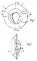
- a hip prosthesis 1 includes an outer surface 2, an inner femoral head receiving surface 3, a planar face 4 and an annular flange 5.
- the prosthesis 1 is made of high density polyethylene.
- the femoral head receiving surface comprises a spherical part 6 and a cylindrical part 7.
- the cylindrical part 7 has the same radius as the spherical part.
- the centre of the spherical part 6 lies on the axis 8 of the cylindrical surface 7.
- the central axis 8 is at an angle to the normal 9 to the plane containing the face 4 of 41.5°.
- a lip 10 is formed between the edge of the spherical part 6 and the face 4 which deters dislocation of the femoral head component.
- the centre 13 of the spherical part 6 of the bore lies on the central axis 9 of the prosthesis.
- Grooves 11 are formed in the outer surface 2 of the prosthesis which are used to help attach the hip prosthesis to the human pelvis.
- a chamfer 12 is included in the face 4 to increase the range of movement of the femoral component, the chamber 12 lying substantially parallel to the axis 8 of the cylindrical surface.
- the prosthesis shown is a left-handed prosthesis in which a chamfer is at the left hand side of the axis 8.
- a right handed prosthesis would be of similar construction with the chamfer situated at the right hand side of the axis of the cylindrical surface.
Description
- This invention relates to improvements in acetabular prostheses used in artificial hip joints.
- In the surgical operation of total hip replacement, an acetabular prosthesis is inserted into an acetabulum in the human pelvis and a mating femoral component is inserted in the femur. After such a hip replacement operation one of the major problems is the danger of dislocation of the hip normally as a result of particular movements of the subject. This is particularly common after a revisionary operation.
- US patent specification No. 3829904 describes an acetabular prosthesis comprising an outer surface and an inner femoral head receiving surface, which two surfaces have their spherical centres displaced and their axes of symmetry mutually angled at approximately 20°. The displacement of the centres of the two surfaces and the mutual angling of the two axes of symmetry serve to provide an increased wall thickness in the main load bearing region of the prosthesis. This is advantageous in preventing early penetration of the acetabular prosthesis by the associated femoral component, but does not offer adequate protection against dislocation, which is the aim of the present invention.
- According to this invention there is provided an acetabular prosthesis including an outer surface, a femoral head receiving surface and a face which joins the edges of these two surfaces, the femoral head receiving surface comprising a blind bore extending from the face towards the outer surface, characterised in that the bore extends along an axis which is at an angle of between 47° and 36.5° to the normal to the plane defined by at least a major portion of the edge of the outer surface.
- Preferably the blind bore comprises a spherical part and a cylindrical part, the radius of the cylindrical part being the same as that of the spherical part, and the centre of the spherical part being on the axis of the cylindrical part. Preferably the axis of the cylindrical part lies at an angle of 41.5° to the normal to the plane defined by the major part of the edge of the outer surface.
- In many acetabular prostheses the face of the prosthesis lies on the plane defined by the edge of the outer surface, but in other protheses the face is non-planar and lies between the plane and the outer surface.
- Thus the acetabular prosthesis does not limit the range of movement of the femoral component but deters dislocation since the angled spherical surface together with the face form a lip which serves to increase the distance through which the femoral head has to rotate before coming out of the blind bore.
- Preferably the prosthesis is mounted in the pelvis such that the direction of the plane in which dislocation is most likely to occur is aligned with the axis of the blind bore forming the femoral head receiving surface. In this position the position where the lip is greatest is aligned with the plane in which dislocation is most likely to occur.
- The angle between the axis of the cylindrical part of the femoral head receiving surface and the normal to the plane is limited by the cylindrical surface fouling the outer surface of the prosthesis when the angle is too large. The most preferable angle is 41.5°.
- Preferably the face of the prosthesis is chamfered to increase the range of movement of the femoral component.
- The centre of the circle surface may lie on the central axis of the prosthesis but may be offset to give an increased thickness between the femoral head receiving surface and the outer surface of the prosthesis at the point where most stress is applied.
- The prosthesis may not include a flange, but preferably does include a flange.
- The socket may be made of any suitable material, for instance high density polyethylene.
- An example of an acetabular hip prosthesis will now be described with reference to the accom-- panying drawings, in which:-
- Figure 1 is a plan view of an acetabular prosthesis;
- Figure 2 is a side projection of the prosthesis;
- Figure 3 is a view of the outer surface of the prosthesis;
- Figure 4 is a section along the line A-A of Figure 1; and
- Figure 5 is a section along the line B-B of Figure 1.
- A hip prosthesis 1 includes an outer surface 2, an inner femoral
head receiving surface 3, a planar face 4 and anannular flange 5. The prosthesis 1 is made of high density polyethylene. - The femoral head receiving surface comprises a
spherical part 6 and a cylindrical part 7. The cylindrical part 7 has the same radius as the spherical part. The centre of thespherical part 6 lies on the axis 8 of the cylindrical surface 7. The central axis 8 is at an angle to the normal 9 to the plane containing the face 4 of 41.5°. Alip 10 is formed between the edge of thespherical part 6 and the face 4 which deters dislocation of the femoral head component. - The
centre 13 of thespherical part 6 of the bore lies on the central axis 9 of the prosthesis. -
Grooves 11 are formed in the outer surface 2 of the prosthesis which are used to help attach the hip prosthesis to the human pelvis. Achamfer 12 is included in the face 4 to increase the range of movement of the femoral component, thechamber 12 lying substantially parallel to the axis 8 of the cylindrical surface. - The prosthesis shown is a left-handed prosthesis in which a chamfer is at the left hand side of the axis 8.
- A right handed prosthesis would be of similar construction with the chamfer situated at the right hand side of the axis of the cylindrical surface.
Claims (11)
Applications Claiming Priority (2)
| Application Number | Priority Date | Filing Date | Title |
|---|---|---|---|
| GB8303188 | 1983-02-04 | ||
| GB838303188A GB8303188D0 (en) | 1983-02-04 | 1983-02-04 | Acetabular prostheses |
Publications (2)
| Publication Number | Publication Date |
|---|---|
| EP0118194A1 EP0118194A1 (en) | 1984-09-12 |
| EP0118194B1 true EP0118194B1 (en) | 1987-04-22 |
Family
ID=10537516
Family Applications (1)
| Application Number | Title | Priority Date | Filing Date |
|---|---|---|---|
| EP19840300594 Expired EP0118194B1 (en) | 1983-02-04 | 1984-01-31 | Improvements in acetabular prostheses |
Country Status (8)
| Country | Link |
|---|---|
| EP (1) | EP0118194B1 (en) |
| JP (1) | JPS59192365A (en) |
| AU (1) | AU578013B2 (en) |
| DE (1) | DE3463219D1 (en) |
| DK (1) | DK159046C (en) |
| GB (1) | GB8303188D0 (en) |
| IE (1) | IE54920B1 (en) |
| NO (1) | NO157602C (en) |
Cited By (1)
| Publication number | Priority date | Publication date | Assignee | Title |
|---|---|---|---|---|
| CN103598933A (en) * | 2013-10-30 | 2014-02-26 | 嘉思特华剑医疗器材(天津)有限公司 | Hip joint prosthesis |
Families Citing this family (9)
| Publication number | Priority date | Publication date | Assignee | Title |
|---|---|---|---|---|
| US6005162A (en) * | 1988-04-20 | 1999-12-21 | Norian Corporation | Methods of repairing bone |
| US6002065A (en) * | 1988-04-20 | 1999-12-14 | Norian Corporation | Kits for preparing calcium phosphate minerals |
| US5962028A (en) * | 1988-04-20 | 1999-10-05 | Norian Corporation | Carbonated hydroxyapatite compositions and uses |
| GB8819587D0 (en) * | 1988-08-17 | 1988-09-21 | Minnesota Mining & Mfg | Rimbearing acetabular component of hip joint prosthesis |
| US5217499A (en) * | 1988-08-17 | 1993-06-08 | Minnesota Mining And Manufacturing Company | Rim-bearing acetabular component of hip joint prosthesis |
| DE19803778B4 (en) * | 1998-01-22 | 2004-02-12 | Steffen Dr. Breusch | hip prosthesis |
| FR2796835B1 (en) * | 1999-07-30 | 2001-11-30 | Merck Biomaterial France | COTYL FOR HIP PROSTHESIS |
| GB0608756D0 (en) * | 2006-05-03 | 2006-06-14 | Benoist Girard Sas | Prosthetic acetabular cup with outwardly projecting flange |
| CN107550604B (en) * | 2017-08-04 | 2023-07-28 | 北京爱康宜诚医疗器材有限公司 | Artificial acetabulum and artificial hip joint |
Family Cites Families (7)
| Publication number | Priority date | Publication date | Assignee | Title |
|---|---|---|---|---|
| GB1296162A (en) * | 1971-03-03 | 1972-11-15 | Thackray C F Ltd | |
| GB1409051A (en) * | 1971-09-24 | 1975-10-08 | Nat Research Department Corp | Hip joint prostheses |
| US3813699A (en) * | 1973-01-15 | 1974-06-04 | R Giliberty | Prosthetic hip joint |
| US4068324A (en) * | 1977-01-19 | 1978-01-17 | Bio-Dynamics Inc. | Platform supported hip prosthesis |
| GB1563334A (en) * | 1977-05-30 | 1980-03-26 | Charnley Surgical Inventions | Acetabular proshesis |
| GB2052997B (en) * | 1979-07-10 | 1983-06-02 | Charnley Surgical Inventions | Acetabular prosthesis |
| EP0091315B1 (en) * | 1982-04-07 | 1986-07-30 | National Research Development Corporation | Endoprosthetic bone joint devices |
-
1983
- 1983-02-04 GB GB838303188A patent/GB8303188D0/en active Pending
-
1984
- 1984-01-31 DE DE8484300594T patent/DE3463219D1/en not_active Expired
- 1984-01-31 EP EP19840300594 patent/EP0118194B1/en not_active Expired
- 1984-02-01 AU AU23963/84A patent/AU578013B2/en not_active Ceased
- 1984-02-02 DK DK46684A patent/DK159046C/en not_active IP Right Cessation
- 1984-02-03 IE IE25584A patent/IE54920B1/en not_active IP Right Cessation
- 1984-02-03 NO NO840416A patent/NO157602C/en unknown
- 1984-02-04 JP JP1767984A patent/JPS59192365A/en active Pending
Cited By (1)
| Publication number | Priority date | Publication date | Assignee | Title |
|---|---|---|---|---|
| CN103598933A (en) * | 2013-10-30 | 2014-02-26 | 嘉思特华剑医疗器材(天津)有限公司 | Hip joint prosthesis |
Also Published As
| Publication number | Publication date |
|---|---|
| DK159046C (en) | 1991-02-04 |
| JPS59192365A (en) | 1984-10-31 |
| DE3463219D1 (en) | 1987-05-27 |
| DK46684A (en) | 1984-08-05 |
| GB8303188D0 (en) | 1983-03-09 |
| NO840416L (en) | 1984-08-06 |
| NO157602C (en) | 1988-04-20 |
| AU578013B2 (en) | 1988-10-13 |
| NO157602B (en) | 1988-01-11 |
| DK46684D0 (en) | 1984-02-02 |
| IE840255L (en) | 1984-08-04 |
| IE54920B1 (en) | 1990-03-14 |
| DK159046B (en) | 1990-08-27 |
| EP0118194A1 (en) | 1984-09-12 |
| AU2396384A (en) | 1984-08-09 |
Similar Documents
| Publication | Publication Date | Title |
|---|---|---|
| EP0812581B1 (en) | Patellar resurfacing component | |
| US4883490A (en) | Acetabular cup | |
| EP0137040B1 (en) | Ball and socket bearing for artificial joint | |
| CA1329449C (en) | Acetabular component of hip joint prosthesis | |
| US5314486A (en) | Non-constrained total joint system | |
| US7169185B2 (en) | Canine acetabular cup | |
| US6136034A (en) | Enarthrodial type joint socket implant | |
| US5702461A (en) | Prosthesis fixturing device | |
| CA2225704C (en) | Modular joint prosthesis augmentation system | |
| EP2129336B1 (en) | An instrument for use in a joint replacement procedure | |
| EP0611008B1 (en) | Locking ring for an acetabular cup | |
| EP1336394B1 (en) | Acetabular prosthesis of the hip | |
| EP0118194B1 (en) | Improvements in acetabular prostheses | |
| US8128705B2 (en) | Assembly for use in implantation of a joint component | |
| US6379389B1 (en) | Artificial hip joint socket | |
| EP2124828B1 (en) | An assembly for use in a hip joint replacement procedure | |
| GB1597003A (en) | Hip joint prosthesis | |
| EP0845250A2 (en) | An osteoprosthesis component | |
| CA2430306C (en) | Prosthesis fixturing device |
Legal Events
| Date | Code | Title | Description |
|---|---|---|---|
| PUAI | Public reference made under article 153(3) epc to a published international application that has entered the european phase |
Free format text: ORIGINAL CODE: 0009012 |
|
| AK | Designated contracting states |
Designated state(s): BE DE FR GB IT NL SE |
|
| 17P | Request for examination filed |
Effective date: 19850305 |
|
| 17Q | First examination report despatched |
Effective date: 19860123 |
|
| GRAA | (expected) grant |
Free format text: ORIGINAL CODE: 0009210 |
|
| AK | Designated contracting states |
Kind code of ref document: B1 Designated state(s): BE DE FR GB IT NL SE |
|
| REF | Corresponds to: |
Ref document number: 3463219 Country of ref document: DE Date of ref document: 19870527 |
|
| ET | Fr: translation filed | ||
| ITF | It: translation for a ep patent filed |
Owner name: FERRAIOLO S.R.L. |
|
| PLBE | No opposition filed within time limit |
Free format text: ORIGINAL CODE: 0009261 |
|
| STAA | Information on the status of an ep patent application or granted ep patent |
Free format text: STATUS: NO OPPOSITION FILED WITHIN TIME LIMIT |
|
| 26N | No opposition filed | ||
| ITTA | It: last paid annual fee | ||
| PGFP | Annual fee paid to national office [announced via postgrant information from national office to epo] |
Ref country code: SE Payment date: 19920122 Year of fee payment: 9 |
|
| PGFP | Annual fee paid to national office [announced via postgrant information from national office to epo] |
Ref country code: NL Payment date: 19920131 Year of fee payment: 9 |
|
| PGFP | Annual fee paid to national office [announced via postgrant information from national office to epo] |
Ref country code: BE Payment date: 19920309 Year of fee payment: 9 |
|
| PG25 | Lapsed in a contracting state [announced via postgrant information from national office to epo] |
Ref country code: BE Effective date: 19930131 |
|
| PG25 | Lapsed in a contracting state [announced via postgrant information from national office to epo] |
Ref country code: SE Effective date: 19930201 |
|
| BERE | Be: lapsed |
Owner name: CHAS F THACKRAY LTD Effective date: 19930131 |
|
| PG25 | Lapsed in a contracting state [announced via postgrant information from national office to epo] |
Ref country code: NL Effective date: 19930801 |
|
| NLV4 | Nl: lapsed or anulled due to non-payment of the annual fee | ||
| EUG | Se: european patent has lapsed |
Ref document number: 84300594.3 Effective date: 19930912 |
|
| PGFP | Annual fee paid to national office [announced via postgrant information from national office to epo] |
Ref country code: DE Payment date: 19960215 Year of fee payment: 13 |
|
| PG25 | Lapsed in a contracting state [announced via postgrant information from national office to epo] |
Ref country code: DE Effective date: 19971001 |
|
| REG | Reference to a national code |
Ref country code: GB Ref legal event code: IF02 |
|
| PGFP | Annual fee paid to national office [announced via postgrant information from national office to epo] |
Ref country code: FR Payment date: 20030128 Year of fee payment: 20 |
|
| PGFP | Annual fee paid to national office [announced via postgrant information from national office to epo] |
Ref country code: GB Payment date: 20030129 Year of fee payment: 20 |
|
| PG25 | Lapsed in a contracting state [announced via postgrant information from national office to epo] |
Ref country code: GB Free format text: LAPSE BECAUSE OF EXPIRATION OF PROTECTION Effective date: 20040130 |
|
| REG | Reference to a national code |
Ref country code: GB Ref legal event code: PE20 |