EP0117851A2 - Arresting brake for mechanical or hydraulic presses - Google Patents
Arresting brake for mechanical or hydraulic presses Download PDFInfo
- Publication number
- EP0117851A2 EP0117851A2 EP84830040A EP84830040A EP0117851A2 EP 0117851 A2 EP0117851 A2 EP 0117851A2 EP 84830040 A EP84830040 A EP 84830040A EP 84830040 A EP84830040 A EP 84830040A EP 0117851 A2 EP0117851 A2 EP 0117851A2
- Authority
- EP
- European Patent Office
- Prior art keywords
- cylinder
- piston
- parking brake
- mechanical
- brake
- Prior art date
- Legal status (The legal status is an assumption and is not a legal conclusion. Google has not performed a legal analysis and makes no representation as to the accuracy of the status listed.)
- Withdrawn
Links
Images
Classifications
-
- B—PERFORMING OPERATIONS; TRANSPORTING
- B30—PRESSES
- B30B—PRESSES IN GENERAL
- B30B15/00—Details of, or accessories for, presses; Auxiliary measures in connection with pressing
- B30B15/28—Arrangements for preventing distortion of, or damage to, presses or parts thereof
- B30B15/287—Arrangements for preventing distortion of, or damage to, presses or parts thereof preventing unintended ram movement, e.g. using blocking devices
Definitions
- the present patent application for an industrial invention has as its object a parking brake for mechanical or hydraulic presses, capable of holding the stationary mass stationary, while allowing sliding if the special mass adjustment devices are actuated, such as for example during the stamp exchange phase.
- the parking brake according to the invention to the content, is studied so that it intervenes automatically, during all the time that it remains actuated, on the electric valve for stopping the flow of compressed air to the clutch-brake group, this is why even if any impulse arrives at the above-mentioned electric valve of the electrical installation of press, it cannot operate until the parking brake remains engaged.
- the invention fundamentally comprises a pneumatic piston, the rod of which plunges into a hydraulic cylinder, where the oil under pressure pushes forward a piston which has, on its external face, a front crest , diametral and wedge-shaped, which will press and fit into a conforming longitudinal groove, hollowed out along a generatrix of a shaft which crosses transversely the hydraulic cylinder and which results anchored to the mass.
- the stopping action in the parking brake according to the invention therefore, is entrusted to the sole adhesion, by sliding friction, of the two converging sides of the aforesaid corner on the lateral edges of the longitudinal groove present on the shaft above.
- the braking wedge rolls by sliding in its place until the driving force exceeds the friction force.
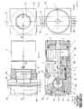
- Fig. 1 is a side view of the parking brake according to the invention.
- Fig. 2 is the orthogonal projection from left to right of FIG. 1.
- Fig. 3 is the section of FIG. 1 with the longitudinal plane A-A.
- Fig. 4 is the orthogonal projection of FIG. 1 from the narrow to the left.
- the invention comprises a pneumatic cylinder (1), single acting, in which a piston (2) moves, the rod of which plunges into a hydraulic cylinder (4), which is coaxial and screwed to the cylinder ( 1).
- the rod (3) ends and slides exactly in a circular duct (5), which is inserted axially into the piston (6) of the cylinder (4), a piston which has a longitudinal extension somewhat less than the length of the master bedroom (4).
- This conduit (5) terminates frontally in a circular chamber (5a), of a slightly larger diameter, from which radiate outwards and backwards small radio-axial conduits (7) through which the oil joins the subtle annular gap (8), which surrounds the rod (3) and which is interposed between the rear face of the piston (6) and the bottom wall (4a) of the cylinder (4).
- the piston (6) has on its outside, anterior face, a diametrical ridge (6a), wedge-shaped, which fits exactly and which slides in a conforming groove (9a) which longitudinally cuts a hollow shaft (9) ), which crosses diametrically the front bottom wall (4b) of the cylinder (4), suitably sized and shaped.
- the oil first, flows back through the radio-axial conduits (7) into the subtle annular chamber (8), located behind the piston (6), then, put under pressure by the pressing rod (3), it pushes forward the udder tone (6), whose front corner (6a) presses and fits into the longitudinal groove (9a) of the shaft (9), which, as we sketched in our introduction, results in solidarity to the mass of the press.
- the oil under pressure can be withdrawn through a special tapped hole (8b) provided on the wall of the cylinder (4), which is collated by a tube to the above-mentioned device intended to inter + capture the compressed air.
- the piston (6) when it advances, obstructs and pushes back two bars (11) which slide longitudinally in the bottom wall (4b) of the cylinder (4) and which press against a circular slide (12), the setback is opposed by an elastic member (13), the preload of which can be adjusted by acting on the nut (14) screwed onto the outer wall of the bottom (4b).
- These cylindrical bars (11) have the role of pushing back in its primitive position and of resting the piston (6) when the parking brake is disconnected, in such a way that the corner (6a) can be detached from the walls of the groove (9a) and therefore the free insertion of the shaft (9), dragged by the mass in its alternative strokes.
- the braking prismatic couple for example, instead of being constituted by a wedge sliding in a corresponding groove executed lengthwise on the shaft (9), as we have described above, could indifferently consist of one or more skates capable of surrounding and holding stationary, by adhesion, the shaft (9).
Landscapes
- Engineering & Computer Science (AREA)
- Mechanical Engineering (AREA)
- Braking Arrangements (AREA)
Abstract
Description
La présente demande de brevet pour une invention industrielle a comme objet un frein de stationnement pour presses mécaniques ou hydrauliques, capable de retenir immobile la masse arrêtée, tout en permettant le glis sement si l'on actionne les dispositifs spéciaux de réglage-masse, comme par exemple pendant la phase de change d'étampes.The present patent application for an industrial invention has as its object a parking brake for mechanical or hydraulic presses, capable of holding the stationary mass stationary, while allowing sliding if the special mass adjustment devices are actuated, such as for example during the stamp exchange phase.
Actuellement aucune presse n'est équipée d'un frein supplémentaire de sûreté, puisque d'habitude on a recours à plusieurs étançons qui sont installés et qui restent sous la masse pendant tout le temps où l'ouvrier doit agir dans l'espace au-dessous de la masse en question.Currently no press is equipped with an additional safety brake, since usually we use several props which are installed and which remain under the mass during all the time when the worker must act in the space above. below the mass in question.
Il est évident, toutefois, que la présence de ces étançons non seulement est d'obstacle, mais quelquefois empêche d'effectuer certaines opérations particulières, comme par exemple celle de réglage pendant la phase de change d'étampes, pendant laquelle la masse doit pouvoir faire des dépla cements verticaux, tant il est vrai que, dans cette circonstance, les étançons sont enlevés et l'on doit, de cette façon, renoncer nécessaire ment à toute sûreté.It is obvious, however, that the presence of these props not only is an obstacle, but sometimes prevents certain special operations, such as that of adjustment during the change of stamping phase, during which the mass must be able to be carried out. make vertical displacements, as it is true that, in this circumstance, the props are removed and one must, in this way, necessarily renounce all security.
Il faut en outre attirer l'attention sur le fait que la disposition des étançons n'exlut ni n'enlève l'habilité à aucun élément de l'installation électrique de la presse, c'est pourquoi, comme il arrive souvent, n'importe quel motif accidentel peut mettre en marche le groupe-moteur et la masse commence sa course vers le bas, avec un impact sur les étançons, qui se brisent ou mettent hors d'usage la presse.It is also necessary to draw attention to the fact that the arrangement of the props does not exclude or take away the ability to any element of the electrical installation of the press, this is why, as it often happens, It does not matter what accidental reason can start the engine group and the mass begins its race downwards, with an impact on the props, which break or put the press out of use.
Le frein de stationnement selon l'invention, au contaire, est étudié de telle façon qu'il intervient automatiquement, pendant tout le temps qu'il reste actionné, sur-la soupape électrique d'arrêt du flux de l'air comprimé vers le groupe de embrayage-frein, c'est pourquoi même si une impulsion quelconque arrive à la susdite soupape électrique de l'installation électrique de la presse, celle-ci ne peut pas entrer en fonction jusqu'à ce que le frein de stationnement reste mis en route.The parking brake according to the invention, to the content, is studied so that it intervenes automatically, during all the time that it remains actuated, on the electric valve for stopping the flow of compressed air to the clutch-brake group, this is why even if any impulse arrives at the above-mentioned electric valve of the electrical installation of press, it cannot operate until the parking brake remains engaged.
Selon la forme préférée de réalisation, l'invention comprend, fondamenta lement, un piston pneumatique dont la tige plonge dans un cylindre hydraulique, où l'huile porté en pression pousse en avant un piston qui a, sur sa face extérieure, une crête frontale, diamétrale et cunéiforme, qui va presser et s'encastrer dans une rainure longitudinale conforme, creusée le long d'une génératrice d'un arbre qui traverse transversalement le cylindre hydraulique et qui résulte ancré à la masse.According to the preferred embodiment, the invention fundamentally comprises a pneumatic piston, the rod of which plunges into a hydraulic cylinder, where the oil under pressure pushes forward a piston which has, on its external face, a front crest , diametral and wedge-shaped, which will press and fit into a conforming longitudinal groove, hollowed out along a generatrix of a shaft which crosses transversely the hydraulic cylinder and which results anchored to the mass.
L'action d'arrêt dans le frein de stationnement selon l'invention, donc, est confiée à la seule adhérence, par frottement de glissement, des deux pans convergents du coin susdit sur les rebords latéraux de la rainure longitudinale présente sur l'arbre susdit.The stopping action in the parking brake according to the invention, therefore, is entrusted to the sole adhesion, by sliding friction, of the two converging sides of the aforesaid corner on the lateral edges of the longitudinal groove present on the shaft above.
La même pression hydraulique qui assure l'avancement et l'encastrement du coin à sa place intervient aussi sur un dispositif, disloqué en aval de la soupape électrique susdite, qui intercepte le flux de l'air vers l'embrayage et celui-ci reste ainsi inactif jusqu'à ce que le frein de stationnement n'est exclu.The same hydraulic pressure which ensures the advancement and the embedding of the corner in its place also intervenes on a device, dislocated downstream of the above-mentioned electric valve, which intercepts the flow of air towards the clutch and the latter remains thus inactive until the parking brake is excluded.
Pendant la phase de change d'étampes, quand actionne les dispositifs de réglage prévus pour faire exécuter les déplacements désirés à la masse, le coin freinant roule en glissant dans sa place jusqu'à ce que la pous sée motrice dépasse la force de frottement.During the stamp exchange phase, when the adjustment devices provided to activate the desired movements of the earth are activated, the braking wedge rolls by sliding in its place until the driving force exceeds the friction force.
Pour une plus claire description de l'invention, l'explication va être faite en référence aux dessins ci-annexés.For a clearer description of the invention, the explanation will be made with reference to the accompanying drawings.
Bien entendu, la description et les dessins ne sont donnés qu'à titre d'exemple indicatif et non limitatif d'une des solutions techniques de réalisation du frein inventé.Of course, the description and the drawings are given only by way of an indicative and non-limiting example of one of the technical solutions for producing the invented brake.
La fig. 1 est une vue latérale du frein de stationnement selon l'invention. La fig. 2 est la projection-orthogonale de la gauche vers la droite de la fig. 1.Fig. 1 is a side view of the parking brake according to the invention. Fig. 2 is the orthogonal projection from left to right of FIG. 1.
La fig. 3 est la section de la fig. 1 avec le plan longitudinal A-A.Fig. 3 is the section of FIG. 1 with the longitudinal plane A-A.
La fig. 4 est la projection orthogonale de la fig. 1 de la troite vers la gauche.Fig. 4 is the orthogonal projection of FIG. 1 from the narrow to the left.
Nous référant aux figures susdites, l'invention comprend un cylindre pneumatique (1), à simple effet, dans lequel se déplace un piston (2) dont la tige plonge dans un cylindre hydraulique (4), qui est coaxial et vissé au cylindre (1).Referring to the above figures, the invention comprises a pneumatic cylinder (1), single acting, in which a piston (2) moves, the rod of which plunges into a hydraulic cylinder (4), which is coaxial and screwed to the cylinder ( 1).
Plus précisément la tige (3) termine et glisse exactement dans un conduit circulaire (5), qui s'enfonce axialement dans le piston (6) du cylindre (4), piston qui présente une extension longitudinale quelque peu inférieure à la longueur de la chambre du cvlindre (4).More precisely, the rod (3) ends and slides exactly in a circular duct (5), which is inserted axially into the piston (6) of the cylinder (4), a piston which has a longitudinal extension somewhat less than the length of the master bedroom (4).
Ce conduit (5) aboutit frontalement dans une chambre circulaire (5a), d'un diamètre légèrement plus grand, d'où rayonnent, vers l'extérieur et en arrière, de petits conduits radio-axiaux (7) par lesquels l'huile rejoint le subtil interstice annulaire (8), qui entoure la tige (3) et qui est interposé entre la face postérieure du piston (6) et la paroi de fond (4a) du cylindre (4).This conduit (5) terminates frontally in a circular chamber (5a), of a slightly larger diameter, from which radiate outwards and backwards small radio-axial conduits (7) through which the oil joins the subtle annular gap (8), which surrounds the rod (3) and which is interposed between the rear face of the piston (6) and the bottom wall (4a) of the cylinder (4).
Le piston (6) a sur sa face extérieure, antérieure, une crête diamétra le (6a), cunéiforme, qui loge exactement et qui glisse dans une rainure conforme (9a) qui coupe longitudinalement, dans toute sa longueur, un arbre creux (9), qui traverse diamétralement la paroi de fond antérieure (4b) du cylindre (4), opportunément dimensionnée et conformée.The piston (6) has on its outside, anterior face, a diametrical ridge (6a), wedge-shaped, which fits exactly and which slides in a conforming groove (9a) which longitudinally cuts a hollow shaft (9) ), which crosses diametrically the front bottom wall (4b) of the cylinder (4), suitably sized and shaped.
Celle-ci résulte, en effet, constituée par un bloc prismatique, presque cubique, traversé par un gros trou central pour l'arbre (9) susdit et par quatre trous périphériques (10), parallèles au central, mais de diamètre plus petit, pour les boulons d'ancrage du frein de stationnement à la structure fixe de support.This results, in fact, constituted by a prismatic block, almost cubic, crossed by a large central hole for the aforementioned tree (9) and by four peripheral holes (10), parallel to the central, but of smaller diameter, for the parking brake anchor bolts to the fixed support structure.
D'après ce que nous venons d'exposer, nous référant aux dessins ci-an nexés, nous pouvons maintenant décrire les modalités de fonctionnement du frein inventé.From what we have just exposed, referring to the attached drawings, we can now describe the operating methods of the invented brake.
Supposons que la masse est arrêtée, dans une position quelconque, et que l'on doit actionner le frein de stationnement.Suppose that the mass is stopped, in any position, and that the parking brake must be applied.
Par un dispositif de commande, soit mécanique qu'électrique, on envoie un fluide aériforme dans le cylindre (1), de telle sorte qu'il cause l'avancement de la tige relative (3) dans le conduit axial (5), naturellement plein d'huile.By means of a control device, both mechanical and electrical, an aerofluid is sent into the cylinder (1), so that it causes the advancement of the relative rod (3) in the axial duct (5), naturally full of oil.
L'huile, d'abord, reflue par les conduits radio-axiaux (7) dans la subtile chambre annulaire (8), située derrière le piston (6), ensuite, mis sous pression par la tige (3) pressante, il pousse en avant le pis ton (6), dont le coin frontal (6a) presse et s'encastre dans la rainure longitudinale (9a) de l'arbre (9), lequel, comme nous l'avons esquissé dans notre introduction, résulte solidaire à la masse de la presse.The oil, first, flows back through the radio-axial conduits (7) into the subtle annular chamber (8), located behind the piston (6), then, put under pressure by the pressing rod (3), it pushes forward the udder tone (6), whose front corner (6a) presses and fits into the longitudinal groove (9a) of the shaft (9), which, as we sketched in our introduction, results in solidarity to the mass of the press.
De la chambre annulaire (8) l'huile en pression peut être prélevé par un trou spécial taraudé (8b) prévu sur la paroi du cylindre (4), qui est collégué par une tubulure au dispositif susdit prévu pour inter+ cepter l'air comprimé pour l'actionnement du groupe frein-embrayage, de telle façon que l'entrée en fonction de la presse soit impossible jusqu'à ce que le frein de stationnement reste actionné.From the annular chamber (8), the oil under pressure can be withdrawn through a special tapped hole (8b) provided on the wall of the cylinder (4), which is collated by a tube to the above-mentioned device intended to inter + capture the compressed air. for actuation of the clutch-clutch group, in such a way that entry into the press is impossible until the parking brake remains actuated.
Le piston (6), quand il avance, fait obstacle et pousse en arrière deux barres (11) qui glissent longitudinalement dans la paroi de fond (4b) du cylindre (4) et qui pressent contre une glissière circulaire (12), dont le reculement est opposé par un organe élastique (13), dont la précharge peut être reglée en agissant sur l'écrou (14) vissé sur la paroi extérieure du fond (4b).The piston (6), when it advances, obstructs and pushes back two bars (11) which slide longitudinally in the bottom wall (4b) of the cylinder (4) and which press against a circular slide (12), the setback is opposed by an elastic member (13), the preload of which can be adjusted by acting on the nut (14) screwed onto the outer wall of the bottom (4b).
Ces barres cylindriques (11) ont le rôle de repousser dans sa position primitive et de repos le piston (6) quand le frein de stationnement est débranché, de telle façon que l'on peut assurer le détachement du coin (6a) des parois de la rainure (9a) et par conséquent le libre enfoncement de l'arbre (9), trainé par la masse dans ses courses alternatives.These cylindrical bars (11) have the role of pushing back in its primitive position and of resting the piston (6) when the parking brake is disconnected, in such a way that the corner (6a) can be detached from the walls of the groove (9a) and therefore the free insertion of the shaft (9), dragged by the mass in its alternative strokes.
Bien entendu, la présente description a été faite nous référant aux des sins ci-annexés, où l'on a illustré la forme préférée de réalisation de l'invention, mais il est évident que de nombreuses modifications et variantes, surtout dans les détails constructifs, pourront être apportées par les techniciens du secteurs, sans pour celà déborder le cadre de la présente invention.Of course, the present description has been made with reference to the sins attached, where the preferred embodiment of the invention has been illustrated, but it is obvious that many modifications and variants, especially in the constructive details, may be made by the technicians of the sector, without this go beyond the scope of the present invention.
Le couple prismatique freinant, par exemple, au lieu d'être constitué par un coin glissant dans une rainure correspondante exécutée longitude nalement sur l'arbre (9), comme nous l'avons décrit ci-dessus, pourra indifféremment consister en un ou plusieurs patins capables d'entourer et de retenir immobile, par adhérence, l'arbre (9).The braking prismatic couple, for example, instead of being constituted by a wedge sliding in a corresponding groove executed lengthwise on the shaft (9), as we have described above, could indifferently consist of one or more skates capable of surrounding and holding stationary, by adhesion, the shaft (9).
Claims (3)
Applications Claiming Priority (2)
| Application Number | Priority Date | Filing Date | Title |
|---|---|---|---|
| IT61083 | 1983-02-23 | ||
| IT00610/83A IT1172468B (en) | 1983-02-23 | 1983-02-23 | PARKING BRAKE FOR MECHANICAL OR HYDRAULIC PRESSES |
Publications (2)
| Publication Number | Publication Date |
|---|---|
| EP0117851A2 true EP0117851A2 (en) | 1984-09-05 |
| EP0117851A3 EP0117851A3 (en) | 1985-10-09 |
Family
ID=11292250
Family Applications (1)
| Application Number | Title | Priority Date | Filing Date |
|---|---|---|---|
| EP84830040A Withdrawn EP0117851A3 (en) | 1983-02-23 | 1984-02-16 | Arresting brake for mechanical or hydraulic presses |
Country Status (2)
| Country | Link |
|---|---|
| EP (1) | EP0117851A3 (en) |
| IT (1) | IT1172468B (en) |
Cited By (2)
| Publication number | Priority date | Publication date | Assignee | Title |
|---|---|---|---|---|
| US5421920A (en) * | 1992-09-24 | 1995-06-06 | Nippon Steel Corporation | Process for producing rolled shape steel material having high strength, high toughness, and excellent fire resistance |
| CN114810879A (en) * | 2022-06-08 | 2022-07-29 | 浙江师范大学 | Composite line control ware |
Citations (5)
| Publication number | Priority date | Publication date | Assignee | Title |
|---|---|---|---|---|
| GB923516A (en) * | 1900-01-01 | |||
| FR847917A (en) * | 1937-12-23 | 1939-10-19 | Schuler L Ag | Hydraulic sheet metal stamping press, single or multiple acting |
| FR944111A (en) * | 1947-03-28 | 1949-03-28 | A E R E M | Mechanical press for cutting, stamping or other application |
| FR1232693A (en) * | 1958-08-26 | 1960-10-11 | Schuler L Ag | Device for fixing the mobile working part, in particular of mechanical presses, preventing their inadvertent closing movement |
| FR2230495A1 (en) * | 1973-05-23 | 1974-12-20 | Jambon Anciens Ateliers H | Hydraulic screw press - fault actuates valve to maintain pressure and lock screws |
-
1983
- 1983-02-23 IT IT00610/83A patent/IT1172468B/en active
-
1984
- 1984-02-16 EP EP84830040A patent/EP0117851A3/en not_active Withdrawn
Patent Citations (5)
| Publication number | Priority date | Publication date | Assignee | Title |
|---|---|---|---|---|
| GB923516A (en) * | 1900-01-01 | |||
| FR847917A (en) * | 1937-12-23 | 1939-10-19 | Schuler L Ag | Hydraulic sheet metal stamping press, single or multiple acting |
| FR944111A (en) * | 1947-03-28 | 1949-03-28 | A E R E M | Mechanical press for cutting, stamping or other application |
| FR1232693A (en) * | 1958-08-26 | 1960-10-11 | Schuler L Ag | Device for fixing the mobile working part, in particular of mechanical presses, preventing their inadvertent closing movement |
| FR2230495A1 (en) * | 1973-05-23 | 1974-12-20 | Jambon Anciens Ateliers H | Hydraulic screw press - fault actuates valve to maintain pressure and lock screws |
Cited By (3)
| Publication number | Priority date | Publication date | Assignee | Title |
|---|---|---|---|---|
| US5421920A (en) * | 1992-09-24 | 1995-06-06 | Nippon Steel Corporation | Process for producing rolled shape steel material having high strength, high toughness, and excellent fire resistance |
| US5985051A (en) * | 1992-09-24 | 1999-11-16 | Nippon Steel Corporation | Shape steel material having high strength, high toughness and excellent fire resistance and process for producing rolled shape steel of said material |
| CN114810879A (en) * | 2022-06-08 | 2022-07-29 | 浙江师范大学 | Composite line control ware |
Also Published As
| Publication number | Publication date |
|---|---|
| IT8300610A0 (en) | 1983-02-23 |
| EP0117851A3 (en) | 1985-10-09 |
| IT1172468B (en) | 1987-06-18 |
Similar Documents
| Publication | Publication Date | Title |
|---|---|---|
| FR2756797A1 (en) | HYDRAULIC BRAKE DEVICE | |
| FR2535267A1 (en) | HYDRAULIC BRAKE SYSTEM WITH BRAKE SLIDER CONTROL, IN PARTICULAR FOR MOTOR VEHICLE | |
| FR2480692A1 (en) | CONTROL DEVICE FOR THE VALVE MECHANISM OF A SERVOFREIN | |
| FR2553723A1 (en) | HYDRAULIC BRAKE SYSTEM WITH SLIDER CONTROL FOR A MOTOR VEHICLE | |
| FR2656049A1 (en) | PISTON PRESSURE ACCUMULATOR, IN PARTICULAR FOR A TRACTION SLIDING CONTROL BRAKE SYSTEM. | |
| FR2518694A1 (en) | HYDRAULICALLY CONTROLLED NON-RETURN VALVE, IN PARTICULAR FOR A REVERSE CONTROL DEVICE FOR HYDRAULIC TAPPING SUPPORT | |
| FR2559723A1 (en) | HYDRAULIC BRAKING SYSTEM WITH SLIDING CONTROL | |
| EP0117851A2 (en) | Arresting brake for mechanical or hydraulic presses | |
| FR2652790A1 (en) | ANTI-LOCK BRAKING HYDRAULIC SYSTEM FOR A MOTOR VEHICLE. | |
| FR2464169A1 (en) | Master cylinder for vehicle hydraulic brake - has cylinder with sliding stepped piston and non return and relief valves | |
| FR2473143A1 (en) | Piston cylinder air brake for railway vehicle - has compressed air driven parking brake piston and spring-mounted secondary piston with common piston rod(BR 21.7.81) | |
| FR2509805A1 (en) | HYDRAULIC FORCE AMPLIFIER | |
| FR2604137A1 (en) | APPARATUS FOR CONTROLLING BRAKE PRESSURE | |
| FR2479929A1 (en) | DISC COUPLING MECHANISM EQUIPPED WITH ASSERTED PISTONS OF DIFFERENT DIMENSIONS | |
| FR2834264A1 (en) | ELECTRO-HYDRAULIC BRAKING CIRCUIT OF A VEHICLE | |
| FR2602835A1 (en) | BRAKE EFFORT HYDRAULIC AMPLIFIER | |
| FR2586983A1 (en) | SLIDING REGULATION BRAKING SYSTEM | |
| FR2611236A1 (en) | HYDRAULIC PISTON WITH AXIAL PISTONS PROVIDED WITH VALVES ANTI RETURN RETURN HYDRAULICALLY CONTROLLED | |
| FR1465713A (en) | Double retaining valve for various hydraulic circuits and especially for those ensuring the steering of vehicles traveling on various terrains | |
| FR2561320A1 (en) | HYDRAULIC PRESSURE TRANSMITTER AND ITS ANNULAR JOINT SEAL | |
| FR2590957A1 (en) | SEAL ARRANGEMENT FOR A PISTON-CYLINDER UNIT | |
| FR2605571A1 (en) | VEHICLE HYDRAULIC BRAKE SYSTEM | |
| FR2515592A1 (en) | BRAKING SYSTEM FOR TRAILERS OF MOTOR VEHICLES | |
| FR2589416A1 (en) | BRAKE PRESSURE GENERATOR | |
| EP0494019B1 (en) | Hydraulic, tappet actuated ejection device with automatic recharging system |
Legal Events
| Date | Code | Title | Description |
|---|---|---|---|
| PUAI | Public reference made under article 153(3) epc to a published international application that has entered the european phase |
Free format text: ORIGINAL CODE: 0009012 |
|
| AK | Designated contracting states |
Designated state(s): AT BE CH DE FR GB LI LU NL SE |
|
| PUAL | Search report despatched |
Free format text: ORIGINAL CODE: 0009013 |
|
| AK | Designated contracting states |
Designated state(s): AT BE CH DE FR GB LI LU NL SE |
|
| 17P | Request for examination filed |
Effective date: 19860409 |
|
| 17Q | First examination report despatched |
Effective date: 19870720 |
|
| STAA | Information on the status of an ep patent application or granted ep patent |
Free format text: STATUS: THE APPLICATION IS DEEMED TO BE WITHDRAWN |
|
| 18D | Application deemed to be withdrawn |
Effective date: 19880604 |