EP0117715A1 - Optical disc players - Google Patents
Optical disc players Download PDFInfo
- Publication number
- EP0117715A1 EP0117715A1 EP84301137A EP84301137A EP0117715A1 EP 0117715 A1 EP0117715 A1 EP 0117715A1 EP 84301137 A EP84301137 A EP 84301137A EP 84301137 A EP84301137 A EP 84301137A EP 0117715 A1 EP0117715 A1 EP 0117715A1
- Authority
- EP
- European Patent Office
- Prior art keywords
- optical disc
- light beam
- signal
- disc
- error signal
- Prior art date
- Legal status (The legal status is an assumption and is not a legal conclusion. Google has not performed a legal analysis and makes no representation as to the accuracy of the status listed.)
- Granted
Links
Images

Classifications
-
- G—PHYSICS
- G11—INFORMATION STORAGE
- G11B—INFORMATION STORAGE BASED ON RELATIVE MOVEMENT BETWEEN RECORD CARRIER AND TRANSDUCER
- G11B7/00—Recording or reproducing by optical means, e.g. recording using a thermal beam of optical radiation by modifying optical properties or the physical structure, reproducing using an optical beam at lower power by sensing optical properties; Record carriers therefor
- G11B7/08—Disposition or mounting of heads or light sources relatively to record carriers
- G11B7/09—Disposition or mounting of heads or light sources relatively to record carriers with provision for moving the light beam or focus plane for the purpose of maintaining alignment of the light beam relative to the record carrier during transducing operation, e.g. to compensate for surface irregularities of the latter or for track following
- G11B7/0948—Disposition or mounting of heads or light sources relatively to record carriers with provision for moving the light beam or focus plane for the purpose of maintaining alignment of the light beam relative to the record carrier during transducing operation, e.g. to compensate for surface irregularities of the latter or for track following specially adapted for detection and avoidance or compensation of imperfections on the carrier, e.g. dust, scratches, dropouts
-
- G—PHYSICS
- G11—INFORMATION STORAGE
- G11B—INFORMATION STORAGE BASED ON RELATIVE MOVEMENT BETWEEN RECORD CARRIER AND TRANSDUCER
- G11B7/00—Recording or reproducing by optical means, e.g. recording using a thermal beam of optical radiation by modifying optical properties or the physical structure, reproducing using an optical beam at lower power by sensing optical properties; Record carriers therefor
- G11B7/08—Disposition or mounting of heads or light sources relatively to record carriers
- G11B7/09—Disposition or mounting of heads or light sources relatively to record carriers with provision for moving the light beam or focus plane for the purpose of maintaining alignment of the light beam relative to the record carrier during transducing operation, e.g. to compensate for surface irregularities of the latter or for track following
- G11B7/0901—Disposition or mounting of heads or light sources relatively to record carriers with provision for moving the light beam or focus plane for the purpose of maintaining alignment of the light beam relative to the record carrier during transducing operation, e.g. to compensate for surface irregularities of the latter or for track following for track following only
- G11B7/0903—Multi-beam tracking systems
-
- G—PHYSICS
- G11—INFORMATION STORAGE
- G11B—INFORMATION STORAGE BASED ON RELATIVE MOVEMENT BETWEEN RECORD CARRIER AND TRANSDUCER
- G11B7/00—Recording or reproducing by optical means, e.g. recording using a thermal beam of optical radiation by modifying optical properties or the physical structure, reproducing using an optical beam at lower power by sensing optical properties; Record carriers therefor
- G11B7/08—Disposition or mounting of heads or light sources relatively to record carriers
- G11B7/09—Disposition or mounting of heads or light sources relatively to record carriers with provision for moving the light beam or focus plane for the purpose of maintaining alignment of the light beam relative to the record carrier during transducing operation, e.g. to compensate for surface irregularities of the latter or for track following
- G11B7/0908—Disposition or mounting of heads or light sources relatively to record carriers with provision for moving the light beam or focus plane for the purpose of maintaining alignment of the light beam relative to the record carrier during transducing operation, e.g. to compensate for surface irregularities of the latter or for track following for focusing only
- G11B7/0909—Disposition or mounting of heads or light sources relatively to record carriers with provision for moving the light beam or focus plane for the purpose of maintaining alignment of the light beam relative to the record carrier during transducing operation, e.g. to compensate for surface irregularities of the latter or for track following for focusing only by astigmatic methods
Definitions
- This invention relates to optical disc players for reproducing optically an information signal from an optical disc, such as an optical digital audio disc, on which the information signal is recorded in a record track formed with an arrangement of a plurality of small pits.
- a light beam is used for reading the information signal from the spiral track.
- the light beam is emitted from an optical head which is moved in the direction of the radius of the optical disc, and the light beam is required to trace correctly the spiral track and to be focused correctly on the surface of the optical disc on which the spiral track is formed.
- tracking control and focus control are performed. In the tracking control, the position of a beam spot formed by the light beam on the surface of the optical disc in relation to the spiral track is detected to produce a tracking detection output.
- a focusing lens in the optical head or the optical head in its entirety is then moved in the direction of the radius of the optical disc in response to the tracking detection output.
- a focusing condition of the light beam on the surface of the optical disc is detected to produce a focus detection output and the focusing lens in the optical head or the optical head in its entirety is moved in the direction perpendicular to the surface of the optical disc in response to the focus detection output.
- a reflected light beam from the optical disc which is modulated in intensity at the surface of the optical disc, is projected onto a photodetector comprising a plurality of photodetecting elements to form a beam spot with its pattern varying in response to the position of the beam spot formed by the light beam on the surface of the optical disc in relation to the spiral track.
- Variations in the pattern of the beam spot on the photodetector are derived in the form of an electric signal obtained by calculation from the outputs of the photodetecting elements of the photodetector.
- detecting arrangements such as so-called “astigmatism systems” and “gable roof prism systems” have been known.
- a reflected light beam from the optical disc which is modulated at the surface of the optical disc, is projected onto a photodetector comprising a plurality of photodetecting elements to form a beam spot with its pattern varying in response to the focusing condition of the light beam on the surface of the optical disc.
- Variations in the pattern of the beam spot on the photodetector are derived in the form of an electric signal obtained by calculation from the outputs of the photodetecting elements of the photodetector.
- the signal obtained by calculation from the outputs of the photodetecting elements is used without being modified as a tracking error signal representing deviations of the beam spot on the surface of the optical disc. from the centre of the spiral track, or as a focusing error signal representing defocus of the light beam on the surface of the optical disc.
- Such a tracking error signal or focus error signal is limited to a predetermined frequency range by being passed through a filter circuit and is then passed to a power amplifier circuit to form a tracking control signal which is supplied to a driving device for tracking control to move the focusing lens in the optical head or the optical head in its entirety in the direction of the radius of the optical disc, or a focus control signal which is supplied to a driving device for focus control to move the focus lens in the optical head or the optical head in its entirety in the direction perpendicular to the surface of the opticial disc.
- the above-mentioned tracking error signal derived by calculation taken a level corresponding to the position of the beam spot on the surface of the optical disc in relation to the spiral track when the beam spot on the surface of the optical disc is positioned on a pit, but takes a constant level independent of the position of the beam spot on the surface of the optical disc in relation to the spiral track when the beam spot is positioned on a plane portion between two successive pits. Therefore, the tracking error signal contains a frequency component resulting from the arrangement of the pits, and does not exactly represent the position of the beam spot relative to the spiral track. Consequently, with the tracking control in the previously proposed optical disc player in which the signal obtained by calculation from the outputs of the photodetecting elements is used without being modified as the tracking error signal, a control such as to move the light beam to trace the spiral track exactly cannot be achieved.
- the pattern of the beam spot on the photodetector varies faithfully in response to the focusing condition of the light beam on the surface of the optical disc independent of the position of the beam spot on the surface of the optical disc in relative to the spiral track when the beam spot is positioned on a plane portion between the pits.
- it varies in response to both the focusing condition of the light beam on the surface of the optical disc and the position of the beam spot on the surface of the optical dis relative to the spiral track when the beam spot is positioned fully or partially on a pit.
- the above-mentioned focus error signal obtained by calculation takes a level corresponding to defocus of the light beam on the surface of the optical disc when the beam spot on the surface of the optical disc is positioned on a plane portion between the pits.
- it takes a level which varies in response to variations in the position of the beam spot on the surface of the optical disc in relation to the spiral disc, and does not correspond to defocus of the light beam on the surface of the optical disc when the beam spot is positioned fully or partially on a pit.
- such a focus error signal not only contains a frequency component resulting from the arrangement of the pits, but is also influenced by variations in the position of the beam spot on the surface of the optical disc, and does not exactly represent defocus of the light beam on the surface of the optical disc. Consequently, with the forcus control in the previously proposed optical disc player in which the signal obtained by calculation from the outputs of the photodetecting elements is used without being modified as the focus error signal, a control such as to cause the light beam to focus exactly on the surface of the optical disc cannot be achieved.
- the tracking error signal or the focus error signal contains the frequency component resulting from the arrangement of the pits, mechanical noise results from this frequency component in the driving device for moving the focusing lens in the optical head or the optical head in its entirety in the direction of the radius of the optical disc or in the direction perpendicular to the surface of the optical disc, when the tracking or focus control signal is supplied to the driving device.
- the optical disc has a non-reflecting portion due to damage or a stain on the surface thereof, a reproduced information signal obtained from the photodetector onto which the reflected light beam from the optical disc is projected is reduced to an extremely low level, and the tracking error signal becomes zero independent of the position of the beam spot on the surface of the optical disc relative to the spiral track. Accordingly, the beam spot is moved towards a location determined by the neutral position of the focusing lens in the optical head at the non-reflecting portion of the surface, so that a track jump movement of the light beam may occur.
- the focus error signal is not obtained and therefore the focusing condition of the light beam on the surface of the optical disc determined in response to the neutral position of the focusing lens in the optical head is taken, and so a large amount of defocus of the light beam may occur.
- an optical disc player for reproducing an information signal recorded in the form of pits arranged in a record track on a disc
- the optical disc player comprising; a light source for generating a light beam, optical means for directing the light beam from said light source onto the disc to be modulated by the record track and reflected therefrom; photodetecting means for receiving a reflected light beam from the disc to produce in response to the received light beam an output from which a reproduced information signal can be obtained;
- a tracking error signal which is not affected by the arrangement of the pits and represents exactly a position of the beam spot formed by the light beam on the optical disc in relation to the record track, and a focus error signal which is also not affected by the arrangement of the pits and represents exactly defocus of the light beam on the optical disc can be obtained, and in response to the tracking error signal and the focus error signal thus obtained, respectively, a tracking control operative to move the light beam to trace accurately the record track, and a focus control operative to cause the light beam directed to the optical disc accurately to focus on the optical disc can be achieved.
- Figure 1 shows a part of the previously proposed optical disc player in which an optical arrangement forming an optical head and a circuit for deriving a reproduced information signal and tracking and focus error signals are included.
- a laser light beam emitted from a laser light source 1 is directed, through an iris 2 which is provided as occasion demands, a polarized beam splitter 3, a quarter-wave plate 4 and an object lens 5 serving as a focusing lens, to impinge on an optical disc 6 on which an information signal is recorded in the form of pits arranged in a spiral record track.
- the laser light beam incident thereupon is modulated in intensity and reflected, and the reflected laser light beam passes through the object lens 5 and the quarter-wave plate 4 to the polarized beam splitter 3.
- the reflected laser light beam is deflected at the polarized beam splitter 3 to be guided to a photodetecting assembly 7.
- the photodetecting assembly 7 detects the reflected laser light beam to produce an output signal which varies in response to variations in the reflected laser light beam and is supplied to an operational circuit 8.
- a reproduced information signal, a first resultant signal used as a tracking error signal and a second resultant signal used as a focus error signal are produced from the output signal of the photodetecting assembly 7.
- the first and second resultant signals are supplied to a driving device 9 for moving the object lens 5 both in the direction of the radius of the optical disc 6 and in the direction perpendicular to the surface of the optical disc 6 so as to carry out tracking and focus controls.
- Figure 2 shows an example of a combination of the photodetecting assembly 7 and the operational circuit 8 shown in Figure 1.
- the photodetecting assembly 7 comprises a first photodetector 11 composed of two photodetecting elements lla and llb on which the reflected laser light beam is projected and a second photodetector 12 composed of four photodetecting elements 12a, 12b, 12c and 12d on which the reflected laser light beam is also projected.
- the operational circuit 8 comprises a subtractor 20a for deriving the difference between the outputs of the photodetecting elements lla and llb, an adder 20b for deriving the sum of the outputs of the photodetecting elements 12a and 12c, an adder 20c for deriving the sum of the outputs of the photodetecting elements 12b and 12d, a subtractor 20d for deriving the difference between the outputs of the adders 20b and 20c, and an adder 20e for summing the outputs of the photodetecting elements 12a, 12b, 12c and 12d.
- the first photodetector 11 and the subtractor 20a form an arrangement for producing the first resultant signal TE O , which is used as the tracking error signal in the optical disc player of Figure 1, in accordance with a so-called push-pull system
- the second photodetector 12 the adders 20b and 20c, and the subtractor 20d form an arrangement for producing the second resultant single FE O , which is used as the focus error signal in the optical disc player shown in Figure 1, in accordance with a so-called astigmatism system.
- the adder 20e produces the reproduced information signals RF 0 from the outputs of the four photodetecting elements 12a to 12d forming the second photodetector 12.
- the first and second resultant signals TE O and TFO obtained from the subtractors 20a and 20d, respectively, are used without being modified as the tracking and focus error signals, and this results in the aforementioned problems.
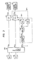
- Figure 3 shows part of one example of the optical disc player according to the present invention.
- This example employs an optical arrangement forming an optical head as shown in Figure 1 and an optical disc on which an information signal is recorded in the form of pits arranged in a spiral record track or a plurality of record tracks formed into concentric circles.
- the first and second photodetectors 11 and 12 as shown in Figure 2 are also employed for receiving a reflected laser light beam passing through the optical arrangement as shown in Figure 1 from the optical disc and an operational circuit 20 which corresponds to the operational circuit 8 shown in Figure 2 is provided to be supplied with the outputs of the first and second photodetectors 11 and 12. Accordingly, the first resultant signal TE 0 , the second resultant signal FE O and the reproduced information signal RF 0 obtained as described above are also derived from the operational circuit 20.
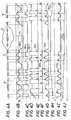
- the first resultant signal TE Q which is used as the tracking error signal in the optical disc player of Figure 1, has a waveform which as shown in Figure 4G takes a level corresponding to the position of a beam spot formed by the laser light beam on the optical disc in relation to the record track when the beam spot on the optical disc is positioned fully on one of the pits P arranged as shown in Figure 4A.
- the second resultant signal FE 0 which is used as the focus error signal in the optical disc player of Figure 1, appears with a waveform which as shown in Figure 41 takes a level corresponding to defocus of the laser light beam projected onto the optical disc when the beam spot formed by the laser light beam on the optical disc is positioned fully on a plane portion between the pits P arranged as shown in Figure 4A.
- the reproduced information signal RF 0 which appears with a waveform as shown in Figure 4B is supplied to a sampling pulse generating circuit 30.
- This sampling pulse generating circuit 30 produces a first sampling plust SP T appearing as shown in Figure 4E when the beam spot formed by the laser light beam on the optical disc is positioned fully on the pit P and a second sampling pulse SP F appearing as shown in Figure 4F when the beam spot formed by the laser light beam on the optical disc is positioned fully on the plane portion of the optical disc between the pits P on the basis of the reproduced information signal RF 0 .
- the reproduced information signal RF 0 is supplied to a voltage comparator 31 and compared with a reference voltage V 0 thereat to produce a reformed reproduced information signal RF X having a rectangular waveform as shown in Figure 4C.
- the reformed reproduced information signal RF X is supplied to a delay circuit 32 to be delayed by a predetermined time ⁇ , so that a rectangular waveform signal RF Y , having a falling edge at each instant at which the beam spot formed by the laser light beam on the optical disc passes out of the front edge of the pit P, and a rising edge at each instant at which the beam spot passes out of the rear edge of the pit P, as shown in Figure 4F, is obtained from the delay circuit 32.
- the rectangular waveform signal RF Y is supplied to both monostable multivibrators 33 and 34.
- the monostable multivibrator 33 is triggered by each falling edge of the rectangular waveform signal RF Y to produce the first sampling pulse PS T
- the monostable multivibrator 34 is triggered by each rising edge of the rectangular waveform signal RF Y to produce the second sampling pulse SP F .
- the first resultant signal TE 0 derived from the operational circuit 30 and the first sampling pulse SP T are supplied to a first sampling and hold circuit 41, so that the first resultant signal TE 0 is subjected to sampling by the first sampling pulse SP T and the level of the sampled segment of the first resultant signal TE D is held until the next sampling at the first sampling and hold circuit 41.
- the second resultant signal FE 0 derived from the operational circuit 20 and the second sampling pulse SP F are supplied to a second sampling and hold circuit 42, so that the second resultant signal FE 0 is subjected to sampling by the second sampling pulse SP F and the level of the sampled segment of the second resultant signal FE 0 is held until the next sampling at the second sampling and hold circuit 42.
- an output signal TE S of the first sampling and hold circuit 41 obtained by the sampling and holding operation thereat as shown in Figure 4H as a whole represents exactly the position of the beam spot formed by the laser light beam on the optical disc in relation to the record track, and contains virtually no frequency component resulting from the arrangement of the pits P.
- an output signal FE S of the second sampling and hold circuit 42 obtained by the sampling and hold operation thereat as shown in Figure 4J as a whole represents exactly defocus of the laser light beam projected onto the optical disc and scarcely contain a frequency component resulting from the arrangement of the pits P.
- the output signal TE S from the first sampling and hold circuit 41 is supplied to a tracking control circuit 51 as a tracking error signal
- the output signal FE S from the second sampling and hold circuit 42 is supplied to a focus control circuit 52 as a focus error signal.
- the tracking control circuit 51 produces a tracking control signal from the tracking error signal TE S therein and supplies it to the driving device 9 provided to the object lens 5 in the same manner as those in Figure 1 for moving the object lens 5 in the direction of the radius of the optical disc so that tracking control is carried out.
- the focus control circuit 52 produces a focus control signal from the focus error signal FE S therein and supplies it also to the driving device 9 for moving the object lens 5 in the direction perpendicular to the surface of the optical disc so that focus control is carried out.
- the tracking error signal TE S is generated on the basis of the first resultant signal TE D when the beam spot is positioned fully on the pit P and is held until the next generation, and therefore the tracking error signal TE S as a whole represents exactly the position of the beam spot formed by the laser light beam on the optical disc in relation to the record track. Accordingly, the laser light beam directed to the optical disc is controlled to trace correctly the record track under the tracking control performed in response to the tracking error signal TE S .
- the focus error signal FE S is generated on the basis of the second resultant signal FE 0 when the beam spot formed by the laser light beam on the optical disc is positioned fully on the plane portion between the pits P and is held until the next generation, and therefore the focus error signal FE S as a whole represents exactly defocusing of the laser light beam on the optical disc. Accordingly, the laser light beam directed to the optical disc is controlled to focus correctly on the optical disc under the focus control -performed-in response to the focus error signal FE S .
- the tracking error signal TE S and the focus error signal FE S contain virtually no frequency component resulting from the arrangement of the pits P, and therefore the driving device does not cause any harsh mechanical noise when it operates in response to the tracking and focus control signals produced from the tracking and focus error signals, respectively.
- the first resultant signal TE D becomes zero independent of the position of the beam spot formed by the laser light beam on the optical disc in relation to the record track when the laser light beam scans the non-reflecting portion Q, and at that time the reproduced information signal RF 0 has such a low level as to be out of the modulation range m shown in Figure 4B, so that the first sampling pulse SP T is not produced.
- the tracking error signal TE S is held at the level obtained just before the laser light beam started to scan the non-reflecting portion Q while the laser light beam scans the non-reflecting portion Q, so that track jump movement of the laser light beam is prevented from occuring.
- the second sampling pulse SP F is also not produced when the laser light beam scans the non-reflecting portion Q of the optical disc, and therefore the focusing error signal FE S is held at the level obtained just before the laser light beam started to scan the non-reflecting portion Q while the laser light beam scans the non-reflecting portion Q, so that the laser light beam is prevented from having a large amount of defocus.
Abstract
Description
- This invention relates to optical disc players for reproducing optically an information signal from an optical disc, such as an optical digital audio disc, on which the information signal is recorded in a record track formed with an arrangement of a plurality of small pits.
- In an optical disc player for reproducing an information signal from an optical digital audio disc, on which the information signal is recorded in the form of small pits arranged in a spiral track, a light beam is used for reading the information signal from the spiral track. The light beam is emitted from an optical head which is moved in the direction of the radius of the optical disc, and the light beam is required to trace correctly the spiral track and to be focused correctly on the surface of the optical disc on which the spiral track is formed. To make the light beam comply with these requirements, tracking control and focus control are performed. In the tracking control, the position of a beam spot formed by the light beam on the surface of the optical disc in relation to the spiral track is detected to produce a tracking detection output. A focusing lens in the optical head or the optical head in its entirety is then moved in the direction of the radius of the optical disc in response to the tracking detection output. In the focus control, a focusing condition of the light beam on the surface of the optical disc is detected to produce a focus detection output and the focusing lens in the optical head or the optical head in its entirety is moved in the direction perpendicular to the surface of the optical disc in response to the focus detection output.
- To detect the position of the beam spot on the surface of the optical disc in relation to the spiral track, there have been proposed several detecting arrangements. These are classified into two types, one of which uses two special light beams provided in addition to the light beam for reading the information signal, and the other of which does not use any light beam other than the one for reading the information signal. As arrangements of the type operative without two special light beams, detecting arrangements such as so-called "push-pull systems" and "heterodyne systems" have been known. In these detecting arrangements, a reflected light beam from the optical disc, which is modulated in intensity at the surface of the optical disc, is projected onto a photodetector comprising a plurality of photodetecting elements to form a beam spot with its pattern varying in response to the position of the beam spot formed by the light beam on the surface of the optical disc in relation to the spiral track. Variations in the pattern of the beam spot on the photodetector are derived in the form of an electric signal obtained by calculation from the outputs of the photodetecting elements of the photodetector.
- On the other hand, to detect the focus condition of the light beam on the surface of the optical disc, detecting arrangements such as so-called "astigmatism systems" and "gable roof prism systems" have been known. In these detecting arrangements also, a reflected light beam from the optical disc, which is modulated at the surface of the optical disc, is projected onto a photodetector comprising a plurality of photodetecting elements to form a beam spot with its pattern varying in response to the focusing condition of the light beam on the surface of the optical disc. Variations in the pattern of the beam spot on the photodetector are derived in the form of an electric signal obtained by calculation from the outputs of the photodetecting elements of the photodetector.
- In previously proposed optical disc players, the signal obtained by calculation from the outputs of the photodetecting elements is used without being modified as a tracking error signal representing deviations of the beam spot on the surface of the optical disc. from the centre of the spiral track, or as a focusing error signal representing defocus of the light beam on the surface of the optical disc. Such a tracking error signal or focus error signal is limited to a predetermined frequency range by being passed through a filter circuit and is then passed to a power amplifier circuit to form a tracking control signal which is supplied to a driving device for tracking control to move the focusing lens in the optical head or the optical head in its entirety in the direction of the radius of the optical disc, or a focus control signal which is supplied to a driving device for focus control to move the focus lens in the optical head or the optical head in its entirety in the direction perpendicular to the surface of the opticial disc. This results in problems in maintaining the light beam in correct tracking relation to each turn of the spiral track, and in maintaining correct focus of the light beam incident upon the surface of the optical disc. There is also the problem that mechanical noise arises from the driving device for tracking control or focus control. Moreover, if the surface of the optical disc is damaged or stained, a so-called track jump movement may occur by which the beam spot jumps from a certain turn of the sprial track to an adjacent turn of the spiral track.
- In the case of the tracking control arrangement, the above-mentioned tracking error signal derived by calculation taken a level corresponding to the position of the beam spot on the surface of the optical disc in relation to the spiral track when the beam spot on the surface of the optical disc is positioned on a pit, but takes a constant level independent of the position of the beam spot on the surface of the optical disc in relation to the spiral track when the beam spot is positioned on a plane portion between two successive pits. Therefore, the tracking error signal contains a frequency component resulting from the arrangement of the pits, and does not exactly represent the position of the beam spot relative to the spiral track. Consequently, with the tracking control in the previously proposed optical disc player in which the signal obtained by calculation from the outputs of the photodetecting elements is used without being modified as the tracking error signal, a control such as to move the light beam to trace the spiral track exactly cannot be achieved.
- Then, in the case of the focus control arrangement, the pattern of the beam spot on the photodetector varies faithfully in response to the focusing condition of the light beam on the surface of the optical disc independent of the position of the beam spot on the surface of the optical disc in relative to the spiral track when the beam spot is positioned on a plane portion between the pits. However, it varies in response to both the focusing condition of the light beam on the surface of the optical disc and the position of the beam spot on the surface of the optical dis relative to the spiral track when the beam spot is positioned fully or partially on a pit. Accordingly, the above-mentioned focus error signal obtained by calculation takes a level corresponding to defocus of the light beam on the surface of the optical disc when the beam spot on the surface of the optical disc is positioned on a plane portion between the pits. However, it takes a level which varies in response to variations in the position of the beam spot on the surface of the optical disc in relation to the spiral disc, and does not correspond to defocus of the light beam on the surface of the optical disc when the beam spot is positioned fully or partially on a pit. As a result of this, such a focus error signal not only contains a frequency component resulting from the arrangement of the pits, but is also influenced by variations in the position of the beam spot on the surface of the optical disc, and does not exactly represent defocus of the light beam on the surface of the optical disc. Consequently, with the forcus control in the previously proposed optical disc player in which the signal obtained by calculation from the outputs of the photodetecting elements is used without being modified as the focus error signal, a control such as to cause the light beam to focus exactly on the surface of the optical disc cannot be achieved.
- In addition, since the tracking error signal or the focus error signal contains the frequency component resulting from the arrangement of the pits, mechanical noise results from this frequency component in the driving device for moving the focusing lens in the optical head or the optical head in its entirety in the direction of the radius of the optical disc or in the direction perpendicular to the surface of the optical disc, when the tracking or focus control signal is supplied to the driving device.
- Moreover, when the optical disc has a non-reflecting portion due to damage or a stain on the surface thereof, a reproduced information signal obtained from the photodetector onto which the reflected light beam from the optical disc is projected is reduced to an extremely low level, and the tracking error signal becomes zero independent of the position of the beam spot on the surface of the optical disc relative to the spiral track. Accordingly, the beam spot is moved towards a location determined by the neutral position of the focusing lens in the optical head at the non-reflecting portion of the surface, so that a track jump movement of the light beam may occur. Similarly, when the light beam scans the non-reflecting portion, the focus error signal is not obtained and therefore the focusing condition of the light beam on the surface of the optical disc determined in response to the neutral position of the focusing lens in the optical head is taken, and so a large amount of defocus of the light beam may occur.
- According to the present invention there is provided an optical disc player for reproducing an information signal recorded in the form of pits arranged in a record track on a disc, the optical disc player comprising; a light source for generating a light beam, optical means for directing the light beam from said light source onto the disc to be modulated by the record track and reflected therefrom; photodetecting means for receiving a reflected light beam from the disc to produce in response to the received light beam an output from which a reproduced information signal can be obtained; and
- a control circuit including a first circuit portion for generating a tracking error signal from the output of said photodetecting means when a beam spot formed by the light beam on the disc is positioned on a pit, and a second circuit portion for generating a focus error signal from the output of said photodetecting means when the beam spot formed by the light beam on the disc is positioned on a plane portion between pits.
- With embodiments of optical disc player in accordance with the present invention, a tracking error signal which is not affected by the arrangement of the pits and represents exactly a position of the beam spot formed by the light beam on the optical disc in relation to the record track, and a focus error signal which is also not affected by the arrangement of the pits and represents exactly defocus of the light beam on the optical disc can be obtained, and in response to the tracking error signal and the focus error signal thus obtained, respectively, a tracking control operative to move the light beam to trace accurately the record track, and a focus control operative to cause the light beam directed to the optical disc accurately to focus on the optical disc can be achieved. Moreover, in embodiments of optical disc player in accordance with the present invention, since neither the tracking error signal nor the focus error signal contains a frequency component resulting from the arrangement of the pits, harsh mechanical noise is prevented from occuring in a driving device which is supplied with tracking and focus control signals obtained on the basis of these tracking and focus error signals.
- The invention will now be described by way of example with reference to the accompanying drawings, throughout which like parts are referred to by like references, and in which:
- Figure 1 is a schematic illustration showing a part of a previously proposed optical disc player in which an optical arrangement and a circuit for producing a reproduced information signal, a tracking error signal and a focus error signal are included;
- Figure 2 is a schematic block diagram showing one example of a combination of a photodetecting assembly and an operational circuit used in the part of the optical disc player shown in Figure 1;
- Figure 3 is a schematic block diagram showing part of one embodiment of optical disc player according to the present invention; and
- Figures 4A to 4J are waveform diagrams used for explaining the operation of the part of the embodiment shown in Figure 3.
- First, to facilitate understanding of the present invention, a previously proposed optical disc player will be described with reference to Figure 1.
- Figure 1 shows a part of the previously proposed optical disc player in which an optical arrangement forming an optical head and a circuit for deriving a reproduced information signal and tracking and focus error signals are included. A laser light beam emitted from a
laser light source 1 is directed, through an iris 2 which is provided as occasion demands, a polarizedbeam splitter 3, a quarter-wave plate 4 and anobject lens 5 serving as a focusing lens, to impinge on anoptical disc 6 on which an information signal is recorded in the form of pits arranged in a spiral record track. At the surface of theoptical disc 6 in which the record track is formed, the laser light beam incident thereupon is modulated in intensity and reflected, and the reflected laser light beam passes through theobject lens 5 and the quarter-wave plate 4 to the polarizedbeam splitter 3. The reflected laser light beam is deflected at the polarizedbeam splitter 3 to be guided to a photodetectingassembly 7. The photodetectingassembly 7 detects the reflected laser light beam to produce an output signal which varies in response to variations in the reflected laser light beam and is supplied to anoperational circuit 8. At theoperational circuit 8, a reproduced information signal, a first resultant signal used as a tracking error signal and a second resultant signal used as a focus error signal are produced from the output signal of the photodetectingassembly 7. The first and second resultant signals are supplied to adriving device 9 for moving theobject lens 5 both in the direction of the radius of theoptical disc 6 and in the direction perpendicular to the surface of theoptical disc 6 so as to carry out tracking and focus controls. - Figure 2 shows an example of a combination of the photodetecting
assembly 7 and theoperational circuit 8 shown in Figure 1. In this example, the photodetectingassembly 7 comprises afirst photodetector 11 composed of two photodetecting elements lla and llb on which the reflected laser light beam is projected and asecond photodetector 12 composed of four photodetectingelements operational circuit 8 comprises asubtractor 20a for deriving the difference between the outputs of the photodetecting elements lla and llb, anadder 20b for deriving the sum of the outputs of the photodetectingelements adder 20c for deriving the sum of the outputs of the photodetectingelements subtractor 20d for deriving the difference between the outputs of theadders adder 20e for summing the outputs of the photodetectingelements first photodetector 11 and thesubtractor 20a form an arrangement for producing the first resultant signal TEO, which is used as the tracking error signal in the optical disc player of Figure 1, in accordance with a so-called push-pull system, and thesecond photodetector 12, theadders subtractor 20d form an arrangement for producing the second resultant single FEO, which is used as the focus error signal in the optical disc player shown in Figure 1, in accordance with a so-called astigmatism system. Moreover, theadder 20e produces the reproduced information signals RF 0 from the outputs of the four photodetectingelements 12a to 12d forming thesecond photodetector 12. - In this previously proposed optical disc player, the first and second resultant signals TEO and TFO obtained from the
subtractors - An embodiment of optical disc player according to the present invention will now be described with reference to Figures 3 and 4A to 4J.
- Figure 3 shows part of one example of the optical disc player according to the present invention. This example employs an optical arrangement forming an optical head as shown in Figure 1 and an optical disc on which an information signal is recorded in the form of pits arranged in a spiral record track or a plurality of record tracks formed into concentric circles.
- In the example of Figure 3, the first and
second photodetectors operational circuit 20 which corresponds to theoperational circuit 8 shown in Figure 2 is provided to be supplied with the outputs of the first andsecond photodetectors operational circuit 20. - The first resultant signal TEQ, which is used as the tracking error signal in the optical disc player of Figure 1, has a waveform which as shown in Figure 4G takes a level corresponding to the position of a beam spot formed by the laser light beam on the optical disc in relation to the record track when the beam spot on the optical disc is positioned fully on one of the pits P arranged as shown in Figure 4A. On the other hand, the second resultant signal FE0, which is used as the focus error signal in the optical disc player of Figure 1, appears with a waveform which as shown in Figure 41 takes a level corresponding to defocus of the laser light beam projected onto the optical disc when the beam spot formed by the laser light beam on the optical disc is positioned fully on a plane portion between the pits P arranged as shown in Figure 4A.
- The reproduced information signal RF0 which appears with a waveform as shown in Figure 4B is supplied to a sampling
pulse generating circuit 30. This samplingpulse generating circuit 30 produces a first sampling plust SP T appearing as shown in Figure 4E when the beam spot formed by the laser light beam on the optical disc is positioned fully on the pit P and a second sampling pulse SPF appearing as shown in Figure 4F when the beam spot formed by the laser light beam on the optical disc is positioned fully on the plane portion of the optical disc between the pits P on the basis of the reproduced information signal RF0. In the samplingpulse generating circuit 30, the reproduced information signal RF 0 is supplied to avoltage comparator 31 and compared with a reference voltage V0 thereat to produce a reformed reproduced information signal RFX having a rectangular waveform as shown in Figure 4C. The reformed reproduced information signal RFX is supplied to adelay circuit 32 to be delayed by a predetermined time τ, so that a rectangular waveform signal RFY, having a falling edge at each instant at which the beam spot formed by the laser light beam on the optical disc passes out of the front edge of the pit P, and a rising edge at each instant at which the beam spot passes out of the rear edge of the pit P, as shown in Figure 4F, is obtained from thedelay circuit 32. The rectangular waveform signal RFY, is supplied to bothmonostable multivibrators monostable multivibrator 33 is triggered by each falling edge of the rectangular waveform signal RFY to produce the first sampling pulse PST, and themonostable multivibrator 34 is triggered by each rising edge of the rectangular waveform signal RFY to produce the second sampling pulse SPF. - The first resultant signal TE0 derived from the
operational circuit 30 and the first sampling pulse SPT are supplied to a first sampling and holdcircuit 41, so that the first resultant signal TE0 is subjected to sampling by the first sampling pulse SPT and the level of the sampled segment of the first resultant signal TED is held until the next sampling at the first sampling and holdcircuit 41. Similarly, the second resultant signal FE0 derived from theoperational circuit 20 and the second sampling pulse SPF are supplied to a second sampling and holdcircuit 42, so that the second resultant signal FE0 is subjected to sampling by the second sampling pulse SPF and the level of the sampled segment of the second resultant signal FE0 is held until the next sampling at the second sampling and holdcircuit 42. - As described, since the first resultant signal TE0 takes the level corresponding to the position of the beam spot formed by the laser light beam on the optical disc in relation to the record track when the beam spot on the optical disc is positioned fully on the pit P, an output signal TES of the first sampling and hold
circuit 41 obtained by the sampling and holding operation thereat as shown in Figure 4H as a whole represents exactly the position of the beam spot formed by the laser light beam on the optical disc in relation to the record track, and contains virtually no frequency component resulting from the arrangement of the pits P. Similarly, since the second resultant signal FE0 takes the level corresponding to defocus of the laser light beam projected onto the optical disc when the-beam spot is positioned fully on the plane portion between the pits P, an output signal FES of the second sampling and holdcircuit 42 obtained by the sampling and hold operation thereat as shown in Figure 4J as a whole represents exactly defocus of the laser light beam projected onto the optical disc and scarcely contain a frequency component resulting from the arrangement of the pits P. - Then, the output signal TES from the first sampling and hold
circuit 41 is supplied to atracking control circuit 51 as a tracking error signal, and the output signal FES from the second sampling and holdcircuit 42 is supplied to afocus control circuit 52 as a focus error signal. Thetracking control circuit 51 produces a tracking control signal from the tracking error signal TES therein and supplies it to thedriving device 9 provided to theobject lens 5 in the same manner as those in Figure 1 for moving theobject lens 5 in the direction of the radius of the optical disc so that tracking control is carried out. Moreover, thefocus control circuit 52 produces a focus control signal from the focus error signal FES therein and supplies it also to thedriving device 9 for moving theobject lens 5 in the direction perpendicular to the surface of the optical disc so that focus control is carried out. - In an embodiment of optical disc player according to the present invention having the part thus described, the tracking error signal TES is generated on the basis of the first resultant signal TED when the beam spot is positioned fully on the pit P and is held until the next generation, and therefore the tracking error signal TES as a whole represents exactly the position of the beam spot formed by the laser light beam on the optical disc in relation to the record track. Accordingly, the laser light beam directed to the optical disc is controlled to trace correctly the record track under the tracking control performed in response to the tracking error signal TES. Similarly, the focus error signal FES is generated on the basis of the second resultant signal FE0 when the beam spot formed by the laser light beam on the optical disc is positioned fully on the plane portion between the pits P and is held until the next generation, and therefore the focus error signal FES as a whole represents exactly defocusing of the laser light beam on the optical disc. Accordingly, the laser light beam directed to the optical disc is controlled to focus correctly on the optical disc under the focus control -performed-in response to the focus error signal FES.
- Moreover, the tracking error signal TES and the focus error signal FES contain virtually no frequency component resulting from the arrangement of the pits P, and therefore the driving device does not cause any harsh mechanical noise when it operates in response to the tracking and focus control signals produced from the tracking and focus error signals, respectively.
- In the case where the optical disc has a non-reflecting portion Q where the surface is damaged or stained as shown in Figure 1A, the first resultant signal TED becomes zero independent of the position of the beam spot formed by the laser light beam on the optical disc in relation to the record track when the laser light beam scans the non-reflecting portion Q, and at that time the reproduced information signal RF0 has such a low level as to be out of the modulation range m shown in Figure 4B, so that the first sampling pulse SPT is not produced. Therefore, the tracking error signal TES is held at the level obtained just before the laser light beam started to scan the non-reflecting portion Q while the laser light beam scans the non-reflecting portion Q, so that track jump movement of the laser light beam is prevented from occuring. Moreover, the second sampling pulse SPF is also not produced when the laser light beam scans the non-reflecting portion Q of the optical disc, and therefore the focusing error signal FES is held at the level obtained just before the laser light beam started to scan the non-reflecting portion Q while the laser light beam scans the non-reflecting portion Q, so that the laser light beam is prevented from having a large amount of defocus.
Claims (3)
a light source (1) for generating a light beam,
optical means (5) for directing the light beam from said light source (1) onto the disc to be modulated by the record track and reflected therefrom; photodetecting means (11, 12) for receiving a reflected light beam from the disc to produce in response to the received light beam an output from which a reproduced information signal can be obtained; and a control circuit including a first circuit portion (20, 33, 41, 51) for generating a tracking error signal from the output of said photodetecting means (11, 12) when a beam spot formed by the light beam on the disc is positioned on a pit, and a second circuit portion (20, 34, 42, 52) for generating a focus error signal from the output of said photodetecting means (11, 12) when the beam spot formed by the light beam on the disc is positioned on a plane portion between pits.
Applications Claiming Priority (2)
| Application Number | Priority Date | Filing Date | Title |
|---|---|---|---|
| JP58032585A JPS59157854A (en) | 1983-02-28 | 1983-02-28 | Controller of optical disk player |
| JP32585/83 | 1983-02-28 |
Publications (2)
| Publication Number | Publication Date |
|---|---|
| EP0117715A1 true EP0117715A1 (en) | 1984-09-05 |
| EP0117715B1 EP0117715B1 (en) | 1988-06-01 |
Family
ID=12362940
Family Applications (1)
| Application Number | Title | Priority Date | Filing Date |
|---|---|---|---|
| EP84301137A Expired EP0117715B1 (en) | 1983-02-28 | 1984-02-22 | Optical disc players |
Country Status (5)
| Country | Link |
|---|---|
| US (1) | US4633453A (en) |
| EP (1) | EP0117715B1 (en) |
| JP (1) | JPS59157854A (en) |
| CA (1) | CA1224267A (en) |
| DE (1) | DE3471790D1 (en) |
Cited By (6)
| Publication number | Priority date | Publication date | Assignee | Title |
|---|---|---|---|---|
| DE3531579A1 (en) * | 1984-09-14 | 1986-03-27 | Olympus Optical Co., Ltd., Tokio/Tokyo | OPTICAL RECORDING AND PLAYBACK DEVICE |
| WO1986004721A1 (en) * | 1985-02-06 | 1986-08-14 | Deutsche Thomson-Brandt Gmbh | Focus regulation for an apparatus for disc-shaped rotating information supports |
| EP0225258A2 (en) * | 1985-11-28 | 1987-06-10 | Fujitsu Limited | Focus servomechanism control system of optical disc system having offset setting means |
| EP0227445A2 (en) * | 1985-12-21 | 1987-07-01 | Sony Corporation | Methods of and apparatus for focusing servo control |
| EP0252502A2 (en) * | 1986-07-11 | 1988-01-13 | Hitachi, Ltd. | Optical information recording and reproducing apparatus with tracking control by sampling |
| EP0253328A2 (en) * | 1986-07-11 | 1988-01-20 | Hitachi, Ltd. | Light spot position control system and method by sampling servo |
Families Citing this family (6)
| Publication number | Priority date | Publication date | Assignee | Title |
|---|---|---|---|---|
| JPS6278732A (en) * | 1985-10-01 | 1987-04-11 | Olympus Optical Co Ltd | Optical information recording and reproducing device |
| US5003523A (en) * | 1987-03-25 | 1991-03-26 | Sony Corporation | Apparatus for recording and reproducing information on an optical disk with a focus servo system for avoiding influence of traverse signal during search |
| JP2642672B2 (en) * | 1988-06-29 | 1997-08-20 | 富士通株式会社 | Optical disk drive |
| JPH02134732A (en) * | 1988-11-15 | 1990-05-23 | Canon Inc | Information recording and reproducing device |
| JP2723199B2 (en) * | 1992-06-03 | 1998-03-09 | シャープ株式会社 | Tracking servo pull-in circuit device for optical disk player |
| JP3961886B2 (en) * | 2002-06-06 | 2007-08-22 | パイオニア株式会社 | Information recording device |
Citations (4)
| Publication number | Priority date | Publication date | Assignee | Title |
|---|---|---|---|---|
| EP0050967A1 (en) * | 1980-10-25 | 1982-05-05 | Olympus Optical Co., Ltd. | Signal detection system for use in an optically operating reproducing apparatus |
| EP0070408A1 (en) * | 1981-07-16 | 1983-01-26 | Mitsubishi Denki Kabushiki Kaisha | Optical signal reproducing system |
| DE3227300A1 (en) * | 1981-07-22 | 1983-03-03 | Hitachi, Ltd., Tokyo | OPTICAL TRACKING SYSTEM |
| EP0073921A2 (en) * | 1981-09-04 | 1983-03-16 | Hitachi, Ltd. | Method of detecting light spot control signal |
Family Cites Families (1)
| Publication number | Priority date | Publication date | Assignee | Title |
|---|---|---|---|---|
| JPS57208642A (en) * | 1981-06-18 | 1982-12-21 | Toshiba Corp | Focus controller |
-
1983
- 1983-02-28 JP JP58032585A patent/JPS59157854A/en active Pending
-
1984
- 1984-02-22 CA CA000448051A patent/CA1224267A/en not_active Expired
- 1984-02-22 EP EP84301137A patent/EP0117715B1/en not_active Expired
- 1984-02-22 DE DE8484301137T patent/DE3471790D1/en not_active Expired
- 1984-02-23 US US06/582,783 patent/US4633453A/en not_active Expired - Lifetime
Patent Citations (4)
| Publication number | Priority date | Publication date | Assignee | Title |
|---|---|---|---|---|
| EP0050967A1 (en) * | 1980-10-25 | 1982-05-05 | Olympus Optical Co., Ltd. | Signal detection system for use in an optically operating reproducing apparatus |
| EP0070408A1 (en) * | 1981-07-16 | 1983-01-26 | Mitsubishi Denki Kabushiki Kaisha | Optical signal reproducing system |
| DE3227300A1 (en) * | 1981-07-22 | 1983-03-03 | Hitachi, Ltd., Tokyo | OPTICAL TRACKING SYSTEM |
| EP0073921A2 (en) * | 1981-09-04 | 1983-03-16 | Hitachi, Ltd. | Method of detecting light spot control signal |
Cited By (11)
| Publication number | Priority date | Publication date | Assignee | Title |
|---|---|---|---|---|
| DE3531579A1 (en) * | 1984-09-14 | 1986-03-27 | Olympus Optical Co., Ltd., Tokio/Tokyo | OPTICAL RECORDING AND PLAYBACK DEVICE |
| WO1986004721A1 (en) * | 1985-02-06 | 1986-08-14 | Deutsche Thomson-Brandt Gmbh | Focus regulation for an apparatus for disc-shaped rotating information supports |
| US4809253A (en) * | 1985-02-06 | 1989-02-28 | Deutsche Thomson-Brandt Gmbh | Focus control through detection of the rate of error in discs with a control signal inversely dependent on the error rate |
| EP0225258A2 (en) * | 1985-11-28 | 1987-06-10 | Fujitsu Limited | Focus servomechanism control system of optical disc system having offset setting means |
| EP0225258A3 (en) * | 1985-11-28 | 1989-08-16 | Fujitsu Limited | Focus servomechanism control system of optical disc system having offset setting means |
| EP0227445A2 (en) * | 1985-12-21 | 1987-07-01 | Sony Corporation | Methods of and apparatus for focusing servo control |
| EP0227445A3 (en) * | 1985-12-21 | 1988-09-07 | Sony Corporation | Methods of and apparatus for focusing servo control |
| EP0252502A2 (en) * | 1986-07-11 | 1988-01-13 | Hitachi, Ltd. | Optical information recording and reproducing apparatus with tracking control by sampling |
| EP0253328A2 (en) * | 1986-07-11 | 1988-01-20 | Hitachi, Ltd. | Light spot position control system and method by sampling servo |
| EP0253328A3 (en) * | 1986-07-11 | 1989-11-29 | Hitachi, Ltd. | Light spot position control system and method by sampling servo |
| EP0252502A3 (en) * | 1986-07-11 | 1989-11-29 | Hitachi, Ltd. | Optical information recording and reproducing apparatus with tracking control by sampling |
Also Published As
| Publication number | Publication date |
|---|---|
| CA1224267A (en) | 1987-07-14 |
| US4633453A (en) | 1986-12-30 |
| DE3471790D1 (en) | 1988-07-07 |
| JPS59157854A (en) | 1984-09-07 |
| EP0117715B1 (en) | 1988-06-01 |
Similar Documents
| Publication | Publication Date | Title |
|---|---|---|
| US4924455A (en) | Apparatus for generating tracking error signals in a differential phase detection system | |
| US4293944A (en) | Information play-back apparatus with astigmatic auto-focusing | |
| US4669072A (en) | Control apparatus for optical video disk recorder/player | |
| US4587644A (en) | Tracking servocontrol circuits for reducing gain to avoid tracking defect in an optical reproducing apparatus | |
| US4338682A (en) | Tracking servo system of video disc player | |
| JP2799142B2 (en) | optical disk | |
| US4497047A (en) | Optical disc player with focus control during search mode | |
| EP0162702B1 (en) | Tracking control arrangements for use in optical disc players | |
| US4616354A (en) | Tracking control arrangements for use in optical disc players | |
| US4815060A (en) | Optical pickup device with tracking and focusing utilizing a photodetector having four regions | |
| US4581728A (en) | Plural beam tracking servo including delay compensation | |
| EP0117715B1 (en) | Optical disc players | |
| MY123977A (en) | Automatic setting of gain in control loops | |
| EP0116467B1 (en) | Optical disc players | |
| EP0087973B1 (en) | Tracking servo system for optical-disc information reproducing apparatus | |
| US5235583A (en) | Optical scanning for record carriers adapted for reading with differing wavelengths | |
| JP3109708B2 (en) | Optical information recording / reproducing device | |
| EP0525896B1 (en) | Compatible optical scanning device | |
| GB2115580A (en) | Apparatus for optically reading information recorded on a rotable record disc | |
| US5408452A (en) | Optical information recording/reproducing system including novel tracking system | |
| JPH0368456B2 (en) | ||
| CA1206613A (en) | Optical disc players | |
| US5023439A (en) | Arrangement for detecting a signal for effecting a focus control of an optical head | |
| US4504934A (en) | Optical signal reproducing apparatus | |
| KR19990011987A (en) | Tracking Servo Device of DVD System |
Legal Events
| Date | Code | Title | Description |
|---|---|---|---|
| PUAI | Public reference made under article 153(3) epc to a published international application that has entered the european phase |
Free format text: ORIGINAL CODE: 0009012 |
|
| AK | Designated contracting states |
Designated state(s): DE FR GB IT |
|
| 17P | Request for examination filed |
Effective date: 19841219 |
|
| 17Q | First examination report despatched |
Effective date: 19860623 |
|
| ITF | It: translation for a ep patent filed |
Owner name: SOCIETA' ITALIANA BREVETTI S.P.A. |
|
| GRAA | (expected) grant |
Free format text: ORIGINAL CODE: 0009210 |
|
| AK | Designated contracting states |
Kind code of ref document: B1 Designated state(s): DE FR GB IT |
|
| REF | Corresponds to: |
Ref document number: 3471790 Country of ref document: DE Date of ref document: 19880707 |
|
| ET | Fr: translation filed | ||
| PLBE | No opposition filed within time limit |
Free format text: ORIGINAL CODE: 0009261 |
|
| STAA | Information on the status of an ep patent application or granted ep patent |
Free format text: STATUS: NO OPPOSITION FILED WITHIN TIME LIMIT |
|
| 26N | No opposition filed | ||
| ITTA | It: last paid annual fee | ||
| PGFP | Annual fee paid to national office [announced via postgrant information from national office to epo] |
Ref country code: DE Payment date: 20010212 Year of fee payment: 18 |
|
| PGFP | Annual fee paid to national office [announced via postgrant information from national office to epo] |
Ref country code: GB Payment date: 20010221 Year of fee payment: 18 |
|
| REG | Reference to a national code |
Ref country code: GB Ref legal event code: IF02 |
|
| PGFP | Annual fee paid to national office [announced via postgrant information from national office to epo] |
Ref country code: FR Payment date: 20020212 Year of fee payment: 19 |
|
| PG25 | Lapsed in a contracting state [announced via postgrant information from national office to epo] |
Ref country code: GB Free format text: LAPSE BECAUSE OF NON-PAYMENT OF DUE FEES Effective date: 20020222 |
|
| PG25 | Lapsed in a contracting state [announced via postgrant information from national office to epo] |
Ref country code: DE Free format text: LAPSE BECAUSE OF NON-PAYMENT OF DUE FEES Effective date: 20020903 |
|
| GBPC | Gb: european patent ceased through non-payment of renewal fee |
Effective date: 20020222 |
|
| PG25 | Lapsed in a contracting state [announced via postgrant information from national office to epo] |
Ref country code: FR Free format text: LAPSE BECAUSE OF NON-PAYMENT OF DUE FEES Effective date: 20031031 |
|
| REG | Reference to a national code |
Ref country code: FR Ref legal event code: ST |