EP0117640A2 - Diverter valve with integral backflow preventer - Google Patents
Diverter valve with integral backflow preventer Download PDFInfo
- Publication number
- EP0117640A2 EP0117640A2 EP84300519A EP84300519A EP0117640A2 EP 0117640 A2 EP0117640 A2 EP 0117640A2 EP 84300519 A EP84300519 A EP 84300519A EP 84300519 A EP84300519 A EP 84300519A EP 0117640 A2 EP0117640 A2 EP 0117640A2
- Authority
- EP
- European Patent Office
- Prior art keywords
- inlet tube
- valve
- tube
- opening
- diverter valve
- Prior art date
- Legal status (The legal status is an assumption and is not a legal conclusion. Google has not performed a legal analysis and makes no representation as to the accuracy of the status listed.)
- Withdrawn
Links
Images


Classifications
-
- E—FIXED CONSTRUCTIONS
- E03—WATER SUPPLY; SEWERAGE
- E03C—DOMESTIC PLUMBING INSTALLATIONS FOR FRESH WATER OR WASTE WATER; SINKS
- E03C1/00—Domestic plumbing installations for fresh water or waste water; Sinks
- E03C1/02—Plumbing installations for fresh water
- E03C1/10—Devices for preventing contamination of drinking-water pipes, e.g. means for aerating self-closing flushing valves
- E03C1/102—Devices for preventing contamination of drinking-water pipes, e.g. means for aerating self-closing flushing valves using an air gap device
-
- E—FIXED CONSTRUCTIONS
- E03—WATER SUPPLY; SEWERAGE
- E03C—DOMESTIC PLUMBING INSTALLATIONS FOR FRESH WATER OR WASTE WATER; SINKS
- E03C1/00—Domestic plumbing installations for fresh water or waste water; Sinks
- E03C1/02—Plumbing installations for fresh water
- E03C1/10—Devices for preventing contamination of drinking-water pipes, e.g. means for aerating self-closing flushing valves
- E03C1/108—Devices for preventing contamination of drinking-water pipes, e.g. means for aerating self-closing flushing valves having an aerating valve
-
- F—MECHANICAL ENGINEERING; LIGHTING; HEATING; WEAPONS; BLASTING
- F16—ENGINEERING ELEMENTS AND UNITS; GENERAL MEASURES FOR PRODUCING AND MAINTAINING EFFECTIVE FUNCTIONING OF MACHINES OR INSTALLATIONS; THERMAL INSULATION IN GENERAL
- F16K—VALVES; TAPS; COCKS; ACTUATING-FLOATS; DEVICES FOR VENTING OR AERATING
- F16K24/00—Devices, e.g. valves, for venting or aerating enclosures
- F16K24/06—Devices, e.g. valves, for venting or aerating enclosures for aerating only
Definitions
- This invention relates to a diverter valve with integral backflow preventer in the form of a vacuum breaker.
- Backflow preventers each a mechanical device which automatically forestalls the possibility of any unintentional reverse flow in the water distributing system and in one construction comprises a vacuum breaker - a device which, when strategically located in the feed line of the water system, prevents the reverse flow of water by the admission of air, precluding any back siphonage which might occur, (See U.S. Patents 2,303,037 and 3,162,210) - are used in commercial and household installations, for example bidets, Roman Tubs, barber shop and hairdressing salon fixtures, laboratory sinks, food processing facilities, chemical manufacturing and processing facilities, metal plating facilities, just to name a few, to prevent the contamination of the potable water supply.
- a diverter valve with integral backflow preventer in the form of a vacuum breaker is provided.
- a diverter valve with integral backflow preventer in the form of a vacuum breaker comprising a main housing or body, having an integral central chamber portion (preferably a vertically extending symmetrical chamber portion), defined by an internal wall and, vertically directed openings at opposed ends of the housing or body through the housing or body into the central chamber portion, a plurality of laterally directed openings extending from the outer surface of the body through the internal wail of the body, opening into the chamber, an inlet tube in communication with the lowermost of the vertically directed openings and extending a predetermined distance from the lowermost vertically directed opening to an opening (preferably an open end), means between the internal wall defining the chamber and the outer surface of the inlet tube for permitting communication between selected of such laterally directed openings and the inlet tube at a time, a closure reciprocal from a position spaced from the opening in the inlet tube closing the upper end of the diverter valve to the atmosphere, to a position closing the inlet tube opening the upper end of the diverter
- the means permitting communication between selected of such laterally extending openings may comprise a tube having an outer surface whose dimensions correspond substantially to the inner surface dimensions of the wall defining the chamber to provide an intimate close tolerance fit therebetween, the tube having at least one laterally directed aperture therethrough for communication with only selected of such laterally directed openings in the housing or body at a time.
- the internal wall defining the chamber is circular and of constant diameter, and the tube is cylindrical in shape.
- the tube is of greater length than the inlet and housing or body of the valve.
- bidet 20 comprising porcelain fixture 22, having drain 24, spray 26, faucets for introducing hot and cold water 28 and 30, pop-up drain control 32 for opening and closing drain 24 by handle 33 and diverter valve 134 with integral backflow preventer secured, to the rim 35 of the bidet 20 and, by T-connection 36 to each of the faucets 28 and 30.
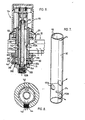
- FIG. 3 With reference to Figures 3, 4, 5, 9 and 10, another diverter valve 34 with integral backflow preventer in the form of a vacuum breaker is shown in cross-section,mounted on the rim of a Roman Bath 37 and comprises a brass body 38 comprising vertically directed lowermost opening 40, vertically directed upper opening 46, and laterally directed openings 42 and 44 through the sides of body 38,all opening into vertically extending symmetrical chamber portion 48 defined by internal circular wall 56.
- the exterior of body 38 is threaded at 50.
- Body 38 also includes radially outwardly extending shoulder rim 52, (providing ledge 52A), screw hole 54 through the threaded portion 50 and circular recess 57 through the radially inner surface of wall 56 to receive "0" ring.60.
- body 38 Proximate the upper extent of opening 40 into chamber 48, body 38 is stepped to provide two ledges 62 and 64, the radially inner edge 62 for supporting axially extending inlet tube 66 spaced from side wall 56 and which inlet tube 66 extends past the upper end of body 38 through opening 46.
- "0" ring 74 and brass washer 74A are positioned above outwardly flared flange 66A as shown to ensure all fluid passing through opening 40 passes through tube 66.
- Annular steel tube 70 having substantially the same outer radial dimensions as the radial dimensions of the inner surface of wall 56 to provide an intimate fit between the outer surface of annular tube 70 and wall 56, sits on teflon washer 71 in turn sitting on washer 74A in ledge 64 and carries laterally directed opening 72 therethrough at the same level as openings 42 and 44.
- Circumferentially elongated aperture 54A (seen best in Figure 9) is provided through tube 70 to align with aperture 54 through body 38 when tube 70 sits on washer 71.
- Tube 70 is longer than tube 66 and carries at Its upper end retainer cap 80 comprising brass casting 82 (see Figure 9) comprising annular portion 86, U-shaped portion 84 cast with annular portion 86 and upstanding arcuate wall formations 88 and 90 also cast with portion 86, each formation 88 and 90 spaced from U-shaped portion 84 by gaps 92 and 94.
- Annular portion 86 carries "0" ring 98 proximate its lower end.
- Threaded blind bore holes 100 are provided from the top of U-shaped portion 84 into U-shaped portion 84 and blind bore hole 101 extends downwardly and opens from the underside,of a central portion of U-shaped portion 84 through central air port 103.
- Travelling pin 102 extends downwardly from bore 101 past annular portion 86 through port 103 and extends into blind bore 104 of check valve float 106.
- Cap 80 of the same radial outer dimensions as the inner dimensions of tube 70, is pushed through end 76 of tube 70 into intimate contact with the inner side wall of tube 70 with "0" ring 98 compressed between brass casting 80 and the interior wall to preclude water passing past the "0" ring at 98.
- Check float valve 106 carries resilient washer 108 at the upper end thereof and downwardly facing annular washer 110 to seat on the upper end of tube 66.
- the upper end of tube 66 is spaced from the bottom of cap 80 by a distance sufficient to permit washer 110 of float 106 to abut tube 66 closing tube 66 while at the same time spacing resilient washer 108 from the bottom of cap 80 when no fluid passes through opening 40 through tube 66, opening chamber 48 to atmosphere.
- the water forces float 106 upwardly causing washer 108 to abut the bottom of cap 80 sealing compartment 48 from the atmosphere causing all water ejected from tube 66 to pass into the space between tube 70 and tube 66.
- float 106 at all times travels between the upper end of tube 66 and the bottom of cap 80 controlled on travelling pin 102.
- tube 70 carrying laterally directed. opening 72, is rotatable to align laterally directed opening 72 with a selected one of openings 42 and 44.
- U-shaped pin 112 See Figure 9
- U-shaped pin 112 is pushed through apertures 114 in tube 70 to extend through gaps 92 and 94 between U-shaped portion 84 and arcuate raised shoulder formations 88 and 90 and then through opposed pin holes 116 in tube 70.
- Handle 120 is in turn secured to U-shaped portion 84 by screws 122 threaded into bore holes 100.
- tube 70 is rotated bringing opening 72 into communication with either opening 42 or 44 directed to, for example, in a Roman Tub the spout of the tub on to the handheld shower.
- Handle Cap 126 seats over handle 120 covering the retaining screws.
- screw 124 is secured through aperture 54 in body 38 and circumferentially elongated aperture 54A.
- An "0" ring 59 is positioned radially inwardly of screws 124.
- Spacers 128 space tube 66 from tube 70.
- diverter valve 34 For mounting diverter valve 34 to tub rim 37 (See Figure 3), the upper portion of body 38 is passed through an aperture in the rim with ledge 52A firmly abutting the rim material surrounding the aperture, and holding nut 130 is threaded on threading 50 on the exterior body 38 and seated on the tub rim lockihg diverter valve into position.
- Canopy 132 covers threaded body portion 50 hiding nut 130.
- diverter valve 134 with integral backflow preventer is constructed similar to valve 34 except that valve 134 is modified for use with bidet 20 shown in Figures 1 and 2 and comprises two sets of laterally directed openings 142 and 144 at two different vertically spaced levels in body 138, one set to be selectively aligned with one set of openings at a time of two different laterally directed sets of openings at two different levels 172A and 172B in tube 170 corresponding to the levels of openings 142 and 144.
- openings 142 would direct water to the rim of the bidet for discharge and opening 144 would direct water to spray 26.
- body 138 has been modified to provide detachable annular ring portion 212 (carrying outlet 144 and aperture215 through which aligning screw 216 is fastened to tube 170 in like manner as aligning screw 124), which sits on ledge 300 of bottom portion 302 of body 138, Washer 200 sits between the underside of the rim 35 of bidet 20 and the top of ring portion 212. Washer 210 and nut 211 sit between the top of rim 35 and nut 130. "0" ring 304 is secured in a recess in portion 212 preclude leakage. Once again other "0" rings are disposed in the valve as required to preclude leakage of water.
Abstract
A diverter valve is provided with an integral backflow preventer in the form of a vacuum breaker. In one embodiment, a diverter valve, for example for a bath, comprises a body (38) having a lower opening (40) for connection to a water supply and two outlet openings (42,44). A tube (70) fits into the body (38) and is rotatable to allow a lateral opening (72) in the tube to be selectively aligned with one or other of the outlets (42,44). Water supplied through the inlet (40) flows through an inner tube (66) to a chamber (48) defined between the two tubes (66, 70) and thence through opening (72) in the outer tube (70). When the water supply is cut off, a float valve (106) closes the top of the innertube (66) and the chamber (48) is in communication with the atmosphere through an air port (103) in a cap (80) fixed to the top of the outer tube (70). When water flows through the inlet (40) the valve (106) is raised to open the inner tube (66) and to close the air port (103). An alternative embodiment for use in a bidet is described, and other applications of the valve are mentioned.
Description
- This invention relates to a diverter valve with integral backflow preventer in the form of a vacuum breaker.
- Backflow preventers, each a mechanical device which automatically forestalls the possibility of any unintentional reverse flow in the water distributing system and in one construction comprises a vacuum breaker - a device which, when strategically located in the feed line of the water system, prevents the reverse flow of water by the admission of air, precluding any back siphonage which might occur, (See U.S. Patents 2,303,037 and 3,162,210) - are used in commercial and household installations, for example bidets, Roman Tubs, barber shop and hairdressing salon fixtures, laboratory sinks, food processing facilities, chemical manufacturing and processing facilities, metal plating facilities, just to name a few, to prevent the contamination of the potable water supply. However these installations use the water in different manners and either separate backflow preventers would be required for each use to protect the water supply from contamination or a separate backflow preventer would be.installed in the line in advance of the components in the system for diverting the water for the different uses. For example, in a bidet, the water is diverted to the rim and the spray. In a bath tub the water is diverted to the spout, showerhead or removeable handheld shower, and so on. While a number of proposals have been made for the diversion of fluids, (See for example, U.S. Patent 4,312,377) not one structure has been provided which also provides backflow prevention, let alone backflow prevention in a compact, easily manufactured, effective unit.
- Particularly in the installation of a bidet, a backflow preventer Model V-360-A Vacuum Breaker manufactured by Sloan Valve Company and a separate diverter valve manufactured by various other manufacturers have been installed with each being serviceable from the outside of the installed fixture. In respect of the installation of a Roman Bath, at the present time, because of the method of installation of faucet and handheld shower, there is no vacuum breaker available for use in such installation and the industry has resorted to the use of a mechanical check valve employing a spring action to close the inlet when the flow of water stops, to overcome this problem. This mechanical check valve has not been approved for such use by the responsible Governmental Authority. To modify existing backflow preventers for use in these installations is not only costly but more importantly, virtually impossible to secure when applied to the installation.
- It is therefore an object of this invention, to provide a diverter valve with integral backflow preventer in the form of a vacuum breaker in an integral structure which is entirely reliable and easily serviced.
- Further and other objects of the invention will be realized by those skilled in the art from the following summary of the invention and detailed description of preferred embodiments thereof.
- According to one aspect of the-invention, a diverter valve with integral backflow preventer in the form of a vacuum breaker is provided.
- According to another aspect of the invention, there is provided a diverter valve with integral backflow preventer in the form of a vacuum breaker comprising a main housing or body, having an integral central chamber portion (preferably a vertically extending symmetrical chamber portion), defined by an internal wall and, vertically directed openings at opposed ends of the housing or body through the housing or body into the central chamber portion, a plurality of laterally directed openings extending from the outer surface of the body through the internal wail of the body, opening into the chamber, an inlet tube in communication with the lowermost of the vertically directed openings and extending a predetermined distance from the lowermost vertically directed opening to an opening (preferably an open end), means between the internal wall defining the chamber and the outer surface of the inlet tube for permitting communication between selected of such laterally directed openings and the inlet tube at a time, a closure reciprocal from a position spaced from the opening in the inlet tube closing the upper end of the diverter valve to the atmosphere, to a position closing the inlet tube opening the upper end of the diverter valve to atmosphere whereby when fluid is fed through the inlet tube into the valve the closure is moved away from the opening in the inlet tube closing the valve to atmosphere to permit the fluid to pass out the opening of the inlet tube into the valve, and when fluid is not passed through the inlet tube, the closure closes the open end of the inlet tube and vents the valve to atmosphere, control means for controlling the means between the internal wall defining the chamber and inlet tube for permitting the lateral selected communication to convey the fluid to the desired opening for discharge and means for mounting the diverter valve with the integral backflow preventer.
- According to another aspect of the invention, the means permitting communication between selected of such laterally extending openings may comprise a tube having an outer surface whose dimensions correspond substantially to the inner surface dimensions of the wall defining the chamber to provide an intimate close tolerance fit therebetween, the tube having at least one laterally directed aperture therethrough for communication with only selected of such laterally directed openings in the housing or body at a time.
- According to another aspect of the invention, the internal wall defining the chamber is circular and of constant diameter, and the tube is cylindrical in shape.
- According to another aspect of the invention, the tube is of greater length than the inlet and housing or body of the valve.
- The invention will now be illustrated with reference to drawings of embodiments of the invention.
-
- Figure 1 is a perspective rear view of a bidet mounting a diverter valve with integral backflow preventer constructed according to one embodiment of the invention.
- Figure 2 is a perspective top view of the bidet shown in Figure 1;
- Figure 3 is a cross-sectional view, taken through a diverter valve with integral backflow preventer constructed according to another embodiment of the invention;
- Figures 4 and 5 illustrate the operation of part of the valve shown in Figure 3;
- Figure 6 is a cross-sectional view of the diverter valve with integral backflow preventer shown in Figures 1 and 2;
- Figure 7 is a perspective view of a component part of the valve shown in Figure 6;
- Figure 8 is a top view of a portion of the valve shown in Figure 6 illustrating part of its operation;
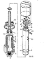
- Figure 9 is an.exploded view of component part of the valve shown in Figure 3;
- Figure 10 is an assembled perspective view partly in section of the valve shown in Figure 9 with a portion of the assembled valve removed. DETAILED DESCRIPTION OF EMBODIMENTS OF THE INVENTION ;
- With reference to Figures 1 and 2, there is shown
bidet 20, comprisingporcelain fixture 22, having drain 24,spray 26, faucets for introducing hot andcold water drain control 32 for opening and closing drain 24 byhandle 33 anddiverter valve 134 with integral backflow preventer secured, to therim 35 of thebidet 20 and, by T-connection 36 to each of thefaucets - With reference to Figures 3, 4, 5, 9 and 10, another
diverter valve 34 with integral backflow preventer in the form of a vacuum breaker is shown in cross-section,mounted on the rim of aRoman Bath 37 and comprises abrass body 38 comprising vertically directedlowermost opening 40, vertically directedupper opening 46, and laterally directedopenings body 38,all opening into vertically extendingsymmetrical chamber portion 48 defined by internalcircular wall 56. The exterior ofbody 38 is threaded at 50.Body 38 also includes radially outwardly extendingshoulder rim 52, (providing ledge 52A), screw hole 54 through the threadedportion 50 andcircular recess 57 through the radially inner surface ofwall 56 to receive "0" ring.60. Proximate the upper extent of opening 40 intochamber 48,body 38 is stepped to provide twoledges inner edge 62 for supporting axially extendinginlet tube 66 spaced fromside wall 56 and whichinlet tube 66 extends past the upper end ofbody 38 throughopening 46. "0" ring 74 andbrass washer 74A are positioned above outwardly flaredflange 66A as shown to ensure all fluid passing through opening 40 passes throughtube 66. -
Annular steel tube 70 having substantially the same outer radial dimensions as the radial dimensions of the inner surface ofwall 56 to provide an intimate fit between the outer surface ofannular tube 70 andwall 56, sits onteflon washer 71 in turn sitting onwasher 74A inledge 64 and carries laterally directed opening 72 therethrough at the same level asopenings elongated aperture 54A (seen best in Figure 9) is provided throughtube 70 to align with aperture 54 throughbody 38 whentube 70 sits onwasher 71. Tube 70 is longer thantube 66 and carries at Its upperend retainer cap 80 comprising brass casting 82 (see Figure 9) comprisingannular portion 86, U-shapedportion 84 cast withannular portion 86 and upstandingarcuate wall formations portion 86, eachformation portion 84 bygaps Annular portion 86 carries "0" ring 98 proximate its lower end. Threadedblind bore holes 100 are provided from the top of U-shapedportion 84 into U-shapedportion 84 andblind bore hole 101 extends downwardly and opens from the underside,of a central portion of U-shapedportion 84 throughcentral air port 103. Travellingpin 102 extends downwardly frombore 101 pastannular portion 86 throughport 103 and extends intoblind bore 104 ofcheck valve float 106.Cap 80 of the same radial outer dimensions as the inner dimensions oftube 70, is pushed throughend 76 oftube 70 into intimate contact with the inner side wall oftube 70 with "0"ring 98 compressed betweenbrass casting 80 and the interior wall to preclude water passing past the "0" ring at 98. - Check
float valve 106 carriesresilient washer 108 at the upper end thereof and downwardly facingannular washer 110 to seat on the upper end oftube 66. The upper end oftube 66 is spaced from the bottom ofcap 80 by a distance sufficient to permitwasher 110 offloat 106 toabut tube 66closing tube 66 while at the same time spacingresilient washer 108 from the bottom ofcap 80 when no fluid passes through opening 40 throughtube 66,opening chamber 48 to atmosphere. However when water passes through opening 40 throughtube 66, the water forces float 106 upwardly causingwasher 108 to abut the bottom ofcap 80sealing compartment 48 from the atmosphere causing all water ejected fromtube 66 to pass into the space betweentube 70 andtube 66. As is apparent,float 106 at all times travels between the upper end oftube 66 and the bottom ofcap 80 controlled on travellingpin 102. - For the purposes of diverting the water passing through
tube 66 into thespace 48 betweentubes tube 70 carrying laterally directed. opening 72, is rotatable to align laterally directedopening 72 with a selected one ofopenings tube 70 for rotation, U-shaped pin 112 (See Figure 9) is pushed throughapertures 114 intube 70 to extend throughgaps U-shaped portion 84 and arcuate raisedshoulder formations opposed pin holes 116 intube 70.Handle 120 is in turn secured to U-shapedportion 84 byscrews 122 threaded intobore holes 100. Therefore,by rotation ofhandle 120,tube 70 is rotated bringing opening 72 into communication with either opening 42 or 44 directed to, for example, in a Roman Tub the spout of the tub on to the handheld shower. Handle Cap 126 seats overhandle 120 covering the retaining screws. - To secure
tube 70 tobody 38 and permit rotation oftube 70 with respect tobody 38,screw 124 is secured through aperture 54 inbody 38 and circumferentiallyelongated aperture 54A. An "0" ring 59 is positioned radially inwardly ofscrews 124. Spacers 128 (like spokes)space tube 66 fromtube 70. - For mounting
diverter valve 34 to tub rim 37 (See Figure 3), the upper portion ofbody 38 is passed through an aperture in the rim with ledge 52A firmly abutting the rim material surrounding the aperture, and holdingnut 130 is threaded on threading 50 on theexterior body 38 and seated on the tub rim lockihg diverter valve into position. Canopy 132 covers threadedbody portion 50hiding nut 130. - With reference to Figures 4 and 5, when water enters
inlet 40 throughtube 66,check valve float 106 is elevated and the fluid passed through the end oftube 66 fallingpast spacers 128 to opening 72 intube 70 and is diverted through one or the other ofopenings tube 70 is rotated by rotatinghandle 120 until opening 72 is aligned with theother opening 44, sealing the other opening (See Figure 5). - While the tolerances between
tube 70 and theinner side wall 56 ofbody 38 provide an intimate fit therebetween because of the precise machining of the parts, nevertheless, some water may pass between the two components and acts as a lubricant. However this water would be precluded from leaking from the valve by the appropriately positioned "0" rings and other seals. - With reference to Figures 6, 7 and 8,
diverter valve 134 with integral backflow preventer is constructed similar tovalve 34 except thatvalve 134 is modified for use withbidet 20 shown in Figures 1 and 2 and comprises two sets of laterally directedopenings body 138, one set to be selectively aligned with one set of openings at a time of two different laterally directed sets of openings at twodifferent levels 172A and 172B intube 170 corresponding to the levels ofopenings openings 142 would direct water to the rim of the bidet for discharge andopening 144 would direct water to spray 26. - Additionally
body 138 has been modified to provide detachable annular ring portion 212 (carryingoutlet 144 and aperture215 through which aligningscrew 216 is fastened totube 170 in like manner as aligning screw 124), which sits onledge 300 ofbottom portion 302 ofbody 138, Washer 200 sits between the underside of therim 35 ofbidet 20 and the top ofring portion 212.Washer 210 andnut 211 sit between the top ofrim 35 andnut 130. "0"ring 304 is secured in a recess inportion 212 preclude leakage. Once again other "0" rings are disposed in the valve as required to preclude leakage of water. - As many changes can be made to the embodiments of the invention without departing from the scope of the invention, it is intended that all matter contained herein be interpreted as illustrative of the invention and not in a limiting sense.
Claims (9)
1. A diverter valve with integral backflow preventer in the form of a vacuum breaker,
2. A diverter valve with integral backflow preventer in the form of a vacuum breaker comprising a main housing or body, having an integral central chamber portion defined by an integral wall and, vertically directed openings at opposed ends of the housing or body through the housing or body into the central chamber portion, a plurality of laterally directed openings extending from the outer surfaces of the body through the internal wall of the body; opening into the chamber, an inlet tube in communication with the lowermost of the vertically directed openings and extending a predetermined distance from the lowermost vertically directed opening to an open end, means between the internal wall defining the chamber and the outer surface of the inlet for permitting communication between selected of such laterally directed openings and the inlet tube at a time, a closure reciprocal from a position spaced from the open end of the inlet tube closing the upper end of the diverter valve to the atmosphere, to a position closing the inlet tube opening the upper end of the diverter valve to atmosphere whereby when fluid is fed through the inlet tube into the valve, the closure is moved away from the end of the inlet tube closing the valve to atmosphere to permit the fluid to pass out the open end of the inlet tube into the valve, and when fluid is not passed through the inlet tube, the closure closes the open end of the inlet tube and vents the valve to atmosphere, control means for controlling the means between the internal wall defining the chamber and inlet tube-for permitting the lateral selected communication to convey fluid to the desired opening for discharge and means for mounting the diverter valve with the integral backflow preventer.
3. The diverter valve with integral backflow preventer in the form of a vacuum breaker of Claim 2, wherein the means permitting communication between selected of such laterally extending openings, comprises a tube having an outer surface whose dimensions correspond substantially to the inner surface dimensions of the wall defining the chamber to provide an intimate close tolerance fit therebetween the tube having at least one laterally directed aperture therethrough for communication with only selected of such laterally directed openings in the housing or body at a time.
4. The diverter valve with integral backflow preventer in the form of a. vacuum breaker of Claim 3, wherein the internal wall defining the chamber portion is circular and of constant diameter, and the tube is cylindrical, in shape.
5. The diverter valve with integral backflow preventer in the form of a vacuum breaker of Claim 4, wherein the tube is of greater length than the inlet tube and housing of the body of the valve.
6. A diverter valve with integral backflow preventer in the form of a vacuum breaker comprising a main housing or body, having an integral central chamber portion defined by an internal wall and, vertically directed openings at opposed ends of the housing or body through the housing or body into the central chamber portion, a plurality of laterally directed openings extending from the outer surface of the body through the internal wall of the body, opening Into the chamber, an inlet tube in communication with the lowermost of the vertically directed openings and extending a predetermined distance from the lowermost vertjcally directed opening to an opening, means between the internal wall defining the chamber and the outer surface of the inlet tube for'permitting communication between selected of such laterally directed openings and the inlet tube at a time, a closure reciprocal from a position spaced from the opening in the inlet tube closing the upper end of the diverter valve to the atmosphere, to a position closing the inlet tube opening the upper end of the diverter valve to atmosphere whereby when fluid is fed through the inlet tube into the valve the closure is moved away from the opening in the inlet tube closing the valve to atmosphere to permit the fluid to pass out the opening of the inlet tube into the valve, and when fluid is not passed through the inlet tube, the closure closes the open end of the inlet tube and vents the valve to atmosphere, control means for controlling the, means between the internal wall defining the chamber and inlet tube for permitting the lateral selected communication to convey the fluid to the desired opening for discharge and means for counting the diverter valve with the integral backflow preventer.
7. The diverter valve with integral backflow preventer in the form of a vacuum breaker of Claim 6, wherein the means permitting communication between selected of such laterally extending openings may comprise a tube having an outer surface whose dimensions correspond substantially to the inner surface dimensions of the wall defining the chamber to provide an intimate close tolerance fit therebetween, the tube having at least one laterally directed aperture therethrough for communication with only selected of such laterally directed openings in the housing or body at a time.
8. The'diverter valve with integral backflow preventer in the form of a vacuum breaker of Claim 7, wherein the internal wall defining the chamber is circular and of constant diameter, and the tube is cylindrical, in shape.
9. The diverter valve with integral backflow preventer in the form of a vacuum breaker of Claim 8, wherein the tube is of greater length than the inlet and housing or body of the valve.
Applications Claiming Priority (2)
| Application Number | Priority Date | Filing Date | Title |
|---|---|---|---|
| CA000420505A CA1194755A (en) | 1983-01-28 | 1983-01-28 | Diverter valve with integral backflow preventer |
| CA420505 | 1983-01-28 |
Publications (2)
| Publication Number | Publication Date |
|---|---|
| EP0117640A2 true EP0117640A2 (en) | 1984-09-05 |
| EP0117640A3 EP0117640A3 (en) | 1986-09-10 |
Family
ID=4124444
Family Applications (1)
| Application Number | Title | Priority Date | Filing Date |
|---|---|---|---|
| EP84300519A Withdrawn EP0117640A3 (en) | 1983-01-28 | 1984-01-27 | Diverter valve with integral backflow preventer |
Country Status (2)
| Country | Link |
|---|---|
| EP (1) | EP0117640A3 (en) |
| CA (1) | CA1194755A (en) |
Cited By (1)
| Publication number | Priority date | Publication date | Assignee | Title |
|---|---|---|---|---|
| EP0527313A1 (en) * | 1991-07-20 | 1993-02-17 | Hans Sasserath & Co Kg | Accouterments for water conduits |
Citations (3)
| Publication number | Priority date | Publication date | Assignee | Title |
|---|---|---|---|---|
| GB978640A (en) * | 1962-12-15 | 1964-12-23 | Shanks & Company Ltd | Valve for controlling the flow of fluids |
| DE2457640A1 (en) * | 1974-12-06 | 1976-06-10 | Wella Ag | Mixer valve for water heating system - has spring loaded valve in by pass working in conjunction with valve in heater element circuit |
| US4312377A (en) * | 1979-08-29 | 1982-01-26 | Teledyne Adams, A Division Of Teledyne Isotopes, Inc. | Tubular valve device and method of assembly |
-
1983
- 1983-01-28 CA CA000420505A patent/CA1194755A/en not_active Expired
-
1984
- 1984-01-27 EP EP84300519A patent/EP0117640A3/en not_active Withdrawn
Patent Citations (3)
| Publication number | Priority date | Publication date | Assignee | Title |
|---|---|---|---|---|
| GB978640A (en) * | 1962-12-15 | 1964-12-23 | Shanks & Company Ltd | Valve for controlling the flow of fluids |
| DE2457640A1 (en) * | 1974-12-06 | 1976-06-10 | Wella Ag | Mixer valve for water heating system - has spring loaded valve in by pass working in conjunction with valve in heater element circuit |
| US4312377A (en) * | 1979-08-29 | 1982-01-26 | Teledyne Adams, A Division Of Teledyne Isotopes, Inc. | Tubular valve device and method of assembly |
Cited By (1)
| Publication number | Priority date | Publication date | Assignee | Title |
|---|---|---|---|---|
| EP0527313A1 (en) * | 1991-07-20 | 1993-02-17 | Hans Sasserath & Co Kg | Accouterments for water conduits |
Also Published As
| Publication number | Publication date |
|---|---|
| EP0117640A3 (en) | 1986-09-10 |
| CA1194755A (en) | 1985-10-08 |
Similar Documents
| Publication | Publication Date | Title |
|---|---|---|
| US4589438A (en) | Diverter valve with integral atmospheric type vacuum breaker | |
| US4856121A (en) | Air gap faucet | |
| US5022429A (en) | Valve assembly for plumbing fixture | |
| US5685330A (en) | Diverter valves with integral back flow preventer and inlet and outlet check valve mechanisms | |
| US4454891A (en) | Air gap drain module for use in a reverse osmosis system | |
| EP0248079B1 (en) | Faucet valve with anti-siphon back flow preventer | |
| MXPA06009556A (en) | Means for covering the flange of a waste water strainer. | |
| GB2284464A (en) | Cartridge for a mixing valve | |
| US5701926A (en) | Backflow prevention device and vacuum breaker for kitchen plumbing | |
| US5970534A (en) | Diverter valves with integral back flow preventer and inlet check and outlet check valve mechanisms and improvements therefor | |
| US4134419A (en) | Tri-combination system | |
| US4805661A (en) | Faucet valve with anti-siphon back flow preventer | |
| US4977920A (en) | Pipe Interrupter | |
| US6035458A (en) | Bidet valve | |
| US6971400B1 (en) | Air gap apparatus | |
| US5518019A (en) | Diverter and volume control valve | |
| US3533554A (en) | Combination aerator and drinking fountain | |
| US6913033B2 (en) | Diverter valve with removable cartridge including integral atmospheric type vacuum breaker and check | |
| WO1996012071A1 (en) | Washbasin valve with integrated water trap | |
| US5038814A (en) | Back flow preventer and integral vacuum breaker | |
| EP0117640A2 (en) | Diverter valve with integral backflow preventer | |
| US6802424B2 (en) | Strainer in shower bath tap valve | |
| CA1225006B (en) | Diverter valve with integral backflow preventer | |
| US7967027B2 (en) | Simple diverter valve for a roman tub with replaceable cartridge including at least two checks | |
| US4757841A (en) | Spout with readily serviceable flow control |
Legal Events
| Date | Code | Title | Description |
|---|---|---|---|
| PUAI | Public reference made under article 153(3) epc to a published international application that has entered the european phase |
Free format text: ORIGINAL CODE: 0009012 |
|
| AK | Designated contracting states |
Designated state(s): FR GB IT |
|
| PUAL | Search report despatched |
Free format text: ORIGINAL CODE: 0009013 |
|
| AK | Designated contracting states |
Kind code of ref document: A3 Designated state(s): FR GB IT |
|
| 17P | Request for examination filed |
Effective date: 19870306 |
|
| 17Q | First examination report despatched |
Effective date: 19880108 |
|
| STAA | Information on the status of an ep patent application or granted ep patent |
Free format text: STATUS: THE APPLICATION IS DEEMED TO BE WITHDRAWN |
|
| 18D | Application deemed to be withdrawn |
Effective date: 19890227 |