EP0117610A2 - Plastics flow control valve - Google Patents
Plastics flow control valve Download PDFInfo
- Publication number
- EP0117610A2 EP0117610A2 EP84300265A EP84300265A EP0117610A2 EP 0117610 A2 EP0117610 A2 EP 0117610A2 EP 84300265 A EP84300265 A EP 84300265A EP 84300265 A EP84300265 A EP 84300265A EP 0117610 A2 EP0117610 A2 EP 0117610A2
- Authority
- EP
- European Patent Office
- Prior art keywords
- valve
- stem
- fitting
- valve body
- flange
- Prior art date
- Legal status (The legal status is an assumption and is not a legal conclusion. Google has not performed a legal analysis and makes no representation as to the accuracy of the status listed.)
- Withdrawn
Links
Images

Classifications
-
- F—MECHANICAL ENGINEERING; LIGHTING; HEATING; WEAPONS; BLASTING
- F16—ENGINEERING ELEMENTS AND UNITS; GENERAL MEASURES FOR PRODUCING AND MAINTAINING EFFECTIVE FUNCTIONING OF MACHINES OR INSTALLATIONS; THERMAL INSULATION IN GENERAL
- F16K—VALVES; TAPS; COCKS; ACTUATING-FLOATS; DEVICES FOR VENTING OR AERATING
- F16K27/00—Construction of housing; Use of materials therefor
- F16K27/06—Construction of housing; Use of materials therefor of taps or cocks
- F16K27/065—Construction of housing; Use of materials therefor of taps or cocks with cylindrical plugs
-
- F—MECHANICAL ENGINEERING; LIGHTING; HEATING; WEAPONS; BLASTING
- F16—ENGINEERING ELEMENTS AND UNITS; GENERAL MEASURES FOR PRODUCING AND MAINTAINING EFFECTIVE FUNCTIONING OF MACHINES OR INSTALLATIONS; THERMAL INSULATION IN GENERAL
- F16K—VALVES; TAPS; COCKS; ACTUATING-FLOATS; DEVICES FOR VENTING OR AERATING
- F16K5/00—Plug valves; Taps or cocks comprising only cut-off apparatus having at least one of the sealing faces shaped as a more or less complete surface of a solid of revolution, the opening and closing movement being predominantly rotary
- F16K5/04—Plug valves; Taps or cocks comprising only cut-off apparatus having at least one of the sealing faces shaped as a more or less complete surface of a solid of revolution, the opening and closing movement being predominantly rotary with plugs having cylindrical surfaces; Packings therefor
- F16K5/045—Particular coverings and materials
Landscapes
- Engineering & Computer Science (AREA)
- General Engineering & Computer Science (AREA)
- Mechanical Engineering (AREA)
- Valve Housings (AREA)
- Lift Valve (AREA)
Abstract
Description
- This invention relates to a flow control valve and more particularly to a rotary plug-type service valve moulded of a high strength plastics material and having a unitary plug and actuator member rotatable in a valve seat of the valve body having inlet and outlet ports connected by compression couplings to a pair of conduits.
- It is well known to fabricate a service valve, such as a ball valve or a plug valve, of moulded polyethylene to include a one-piece body having a valve seat with a first passage opening to the seat and a second passage opening to the seat. A rotary member is positioned in the valve seat and a passageway extending through the rotary member is movable with the rotary member between a closed position where the flow between the first and second passages of the valve body is blocked and an open position where the passage through the rotary member is aligned with the passages in the valve body to permit flow between the first and second passages through the rotary member. The rotary member is provided with seat seals which seal against the wall surrounding the valve body passages to shut off the flow through the passages when the rotary member is turned to the closed position. The valve body includes screw-threaded fitting portions which are connected by compression couplings to conduits or pipes of a piping system.
- It is also known to provide an integral stem and plug arrangment where the stem extends upwardly from the plug and is connected to an adapter for turning the stem. The unitary stem and plug are moulded of polythylene. Because the stem projects upwardly and through the valve body to support the valve actuator, the stem is exposed to external impact blows which are transmitted downwardly through the pressure boundary in the valve to the plug. Accordingly, the stem must have a sufficient cross-sectional area to withstand the impact blows, as well as to withstand the torsional forces transmitted by the valve actuator during operation of the valve.
- In view of the fact that polyethylene is a relatively soft and medium-yield material, a polyethylene valve stem must have a thickness substantially greater than the wall thickness of the polyethylene valve body.
- It is the conventional practice to fabricate the known polyethylene plug and ball valves by an injection moulding process. An integral stem and plug has specific structural requirements that substantially complicate the moulding process. Additionally, because polyethylene is a relatively soft plastics material, the valve parts must include relatively thick sections to safely transmit operating forces. These thick valve sections cause the unit cost to increase because increased injection moulding machine time is required to allow the thicker sections to cool once the mould is filled with injected plastics material. The tooling cost associated with this specialized moulding process is high. Consequently, the overall manufacturing time and cost of fabricating a polyethylene service valve mould are high.
- An additional problem encountered in the operation of polyethylene service valves is the tendency of the valve body parts to creep or migrate away from one another when subjected to high pressure, particularly when the pressure is applied to the seat seal on one side of the plug without a corresponding supporting pressure on the other side of the plug. One solution to controlling this migration or creep is reinforcement of the portion of the valve body that surrounds the plug seat seals. By reinforcing the valve body, the normal tendency of the elastomeric material to creep or separate is overcome by rigidifying the valve body.
- In one method, the valve body is rigidified by providing an enlarged, integral, external reinforcement ring around the valve body opposite the valve seat. It is also known to provide internal reinforcement rings embedded in a valve body around the valve seat. This reinforced structure is designed to prevent separation or migration of the elastomeric material of the valve body away from the plug member around the valve seat.
- The provision of moulded external, as well as, internal reinforcement rings on a valve body requires specialized moulding of the valve body to accommodate the reinforcing structure at localized points externally or internally. The moulded valve body, therefore, does hot have a uniform thickness throughout. The mould for the valve body is considered to be complex because of the need to provide for variations in the wall thickness of the valve body. Such a mould requires complex machine operations to fabricate.
- Another recognized problem is connecting the known plastics valves to a service line without subjecting the sealing gasket of the compression couplings to an excessive force applied by the collar due to over-torquing or uncontrolled rotation of the nut on the valve pipe stub end. If rotation of the nut is not controlled, the gasket may be compressed beyond its ability to maintain an effective seal around the pipe due to the excessive compression of the gasket by the collar as it is advanced upon rotation of the nut.
- Therefore, there is need in a plastics service valve for an integral stem and plug capable of withstanding impact loads directed upon the valve stem, as well as, torsional forces transmitted during operation of the valve and for a compression type coupling that provides complete and controlled compression of a sealing gasket around the pipe and against the body of the fitting.
- In accordance with the present invention, there is provided a flow control valve comprising, a valve body moulded of plastics material and having a chamber with an upper portion and a lower portion, said lower portion having an inlet opening and an outlet opening, a valve seat in said chamber lower portion between said inlet and outlet openings, a valve member positioned in said valve seat between said inlet and outlet openings said valve member being moulded of plastics material to form a unitary body including a plug portion and an actuator portion, said plug portion having a flow passage therethrough, said plug portion being rotatable in said valve seat between an open position where said flow passage is aligned with said inlet and outlet openings and a closed position where said flow passage is out of alignment with said inlet and outlet openings to control the flow of fluid through said chamber lower portion, said actuator portion extending upwardly through said chamber upper portion and including a flange and a stem, said flange and said stem being connected to said plug portion, said flange being spaced circumferentially around said stem and extending upwardly between said valve body and said stem to a position overlying said valve body and thereby closing said chamber upper portion, said stem projecting upwardly from within said flange and above said valve body, said valve body including an upper shoulder extending circumferentially around said chamber upper portion, and said flange being positioned on said upper shoulder so that impact forces applied to said actuator portion are transmitted away from said stem and plug and from said flange to said valve body and distributed throughout the valve body.
- With the valve of the present invention, the force of an external impact blow directed either upon the valve stem or the valve actuator is transmitted uniformly throughout the valve body from the flange of the valve member to the upper shoulder of the valve body and through the valve body to the fittings and therefrom through the pipe couplings to the pipeline. Thus, impact forces are transmitted away from the centreline of the valve stem. With this arrangement, the effect of an impact blow is not localized at the valve stem or the valve actuator, but is diverted away from this portion of the valve and directed to the pipeline system. In this manner, fatigue and stress of the valve member attributed to external impact blows and valve leakage or valve failure, which is known to result therefrom, is reduced.
- Further in accordance with the present invention, there is provided on the valve a pipe coupling that includes a fitting having a body portion with a bore for receiving a pipe. The body portion has a recess surrounding the bore to form an internal shoulder within the fitting. An elastic deformable member is positioned in the recess in abutting relation with the shoulder and is adapted to encircle and seal against the pipe and the fitting body portion. A nut is threadedly connected to the fitting body portion for advancement into the bore. The nut has an internal bore with an internal wedge surface. A pipe-gripping collar has an external wedge surface complementary to and cooperating with the nut internal wedge surface so that the collar is positioned within the nut internal bore and surrounding the pipe. The nut includes an end portion surrounding the collar. The nut end portion has a bearing surface for applying a compressive force which is transmitted to the elastic deformable member to compress the elastic deformable member against the fitting shoulder. The nut is threadedly advanced upon rotation into the fitting bore to apply an axial force upon the elastic deformable member to compress the elastic deformable member to form a seal around the pipe and against the fitting body portion within the fitting and axially advance the collar into frictional engagement with the pipe to retain the pipe within the fitting.
- An embodiment of the present invention will now be described, by way of an example, with reference to the accompanying drawings, in which:
- Figure 1 is a sectional view in side elevation of a-plastics service valve, illustrating the connection of a valve body to a pair of pipes in a pipeline system,
- Figure 2 is a top plan view of the plastics service valve shown in Figure 1, illustrating an actuator of the valve in a closed position,
- Figure 3 is a sectional view taken along line III-III of Figure 1, illustrating the stops on the actuator and valve body for 90° operation of the valve between the open and closed positions,
- Figure 4 is a sectional view taken along line IV-IV of Figure 1, illustrating one of the two seat seals that are secured to a plug portion of a valve member, and
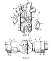
- Figure 5 is an enlarged, exploded, fragmentary, isometric view partially in section of the valve member illustrating an integral plug portion, actuator portion and stem portion and the seat seals that are received within the counterbores of the plug portion.
- Referring to the drawings, and particularly to Figure 1, there is illustrated a service valve generally designated by the
numeral 10 of the rotary plug type which is adapted for use as a distribution valve or service stop for controlling the flow of a fluid, either liquid or gas, through a piping system generally designated by thenumeral 12. Theservice valve 10 includes a valve body generally designated by thenumeral 14 having achamber 16 with anupper portion 18 and alower portion 20. Thelower portion 20 has inlet/outlet openings 22 and 24. Thevalve body 14 also includes conduit orfitting portions fitting portions pipes piping system 12. Theservice conduits fitting portions numeral - The chamber
lower portion 20 of thevalve body 14 includes avalve seat 38 extending between and around the inlet and outlet openings 22 and 24. Avalve member 40 is rotatably positioned in thevalve seat 38 between the openings 22 and 24. Thevalve member 40 is moulded of plastics material to form a unitary body of a substantially uniform thickness throughout having aninternal surface 42 and anexternal surface 44. With this configuration, thevalve member 40 is efficiently moulded, preferably by an injection-moulding process, without requiring enlarged body parts having a thickness greater than the other body parts and thereby increasing the complexity of the moulding process and costs of machining the mould for thevalve member 40. - The
valve member 40 includes anintegral plug portion 46 and anactuator portion 48. As stated above, thevalve member 40 is moulded so that both theplug portion 46 and theactuator portion 48 have substantially the same body thickness to provide uniformity of construction throughout thevalve member 40. Theplug portion 46 has aflow passage 50 therethrough, and is rotatable in thevalve seat 38 between an open position and a closed position. In the open position, theflow passage 50 is aligned with the openings 22 and 24 to permit fluid flow therethrough. In the closed position, as shown in Figure 1, theflow passage 50 is 90° out of alignment with the inlet and outlet openings 22 and 24 to interrupt fluid flow therethrough. - The
plug portion 46 is illustrated in greater detail in Figure 5 and includes a pair of counterbores 52 in the external surface of theplug portion 46. The counterbores 52 are spaced 90* relative to theflow passage 50. Elastomeric inserts 54 are secured in the counterbores 52, as shown in Figures 1 and 4, to serve as seat seals for engaging thevalve seat 38 around the inlet and outlet openings 22 and 24 when thevalve member 40 is in the closed position, as illustrated in Figure 1. Preferably, theinserts 54 are mfded of an elastomeric material, such as Buna N or polyurethane material. - To properly orient and secure the seat seal inserts 54 on the surface of the
plug portion 46, theinserts 54 are provided with a pair of oppositely extending keys ortabs 56 shown in Figure 5 that are received within correspondingkeyways 58 of the counterbores 52. Thekeys 56 have a length corresponding substantially to thekeyways 58 so that when theinserts 54 are positioned in the counterbores 52, they are securely and properly oriented on the surface of theplug portion 46 at the location of the counterbores 52. Theinserts 54 are slightly oversized in relation to the diameters of the plug counterbores 52. Thus, in order to position theinserts 54 in the counterbores 52, theinserts 54 must be radially compressed. When theinserts 54 are positioned in the counterbores 52, they remain radially compressed. With this arrangement, the outer surfaces of theinserts 54 protrude outwardly from theplug portion 46 to assure that theinserts 54 seal against the wall of the chamberlower portion 20 around the openings 22 and 24. - Preferably, the
inserts 54 are formed from an elastomeric material which is molded in the configuration illustrated in Figures 1, 4, and 5. Theinserts 54 have an outer diameter greater than the diameter of the counterbores 52 to the extent that in order to position theinserts 54 in the counterbores 52, the outer circumferential wall of theinserts 54 must be compressed. Thus, when theinserts 54 are firmly in place in the counterbores 52, theinserts 54 are under ccnpression and securely retained in place. To assure a secure engagement of theinserts 54 in the counterbores 52 of theplug portion 46, theinserts 54 must be radially compressed inwardly to fit in the counterbores 52. Once theinserts 54 are in place in the counterbores 52, theinserts 54 are under compression and, thereby, retained in secure abutting relation with the walls of theplug portion 46 around the counterbores 52. With this arrangement, theinserts 54 are prevented from being displaced from the counterbores 52 when they are moved into and out of sealing relation with thevalve body 14 around the openings 22 and 24 which form thevalve seat 38. - As illustrated in Figures 1 and 5, the
valve actuator portion 48 extends upwardly through the valve chamberupper portion 18 to provide an arrangement for closing the valve chamberupper portion 18. Theactuator portion 48 is an integral part of theplug portion 46 and includes aflange 60 and astem 62. Theflange 60 is connected to and, thereby, forms an extension of the peripheral surface of theplug portion 46. Thestem 62 is also connected to theplug portion 46 and extends centrally and upwardly from theplug portion 46. - The
flange 60 is spaced circumferentially around thestem 62. Theflange 60 extends upwardly between thevalve body 14 and thestem 62 to a position overlying thevalve body 14 to, thereby, close the chamberupper portion 18. Thestem 62 projects upwardly within theflange 60 and above thevalve body 14 to facilitate manipulation of thestem 62 to open and close theservice valve 10. - As seen in Figure 1, the
valve member 40 is moulded to provide thestem 62 with aninternal core 64 surrounded by a wall having a thickness corresponding to the wall thickness of theflange 60. Most preferably, theflange 60 and stem 62 are moulded to provide external radial surfaces at apoint 66 where theflange 60 and thestem 62 join theplug portion 46 and atpoints flange 60 overlies thevalve body 14. With this arrangement, theflange 60 and stem 62 are integrally formed with a substantially uniform wall thickness throughout. This feature minimizes internal stresses attendant with the moulding process that are caused by unequal "shrink" of unequal thicknesses of the plastics material as it cools down. The substantially uniform wall, therefore, increases the strength of theflange 60 andstem 62. In addition, the radial surfaces formed at thepoints valve member 40 with increased structural strength to resist impact... forces applied to theflange 60 and thestem 62. The radial forces are operable to distribute impact forces evenly to theflange 60; while, a normally sharp corner atpoints - The
valve body 14, as illustrated in Figure 1, includes anupper shoulder 70 that extends around the chamberupper end portion 18. Theupper shoulder 70 forms a circumferential bearing surface for receiving the bottom surface of theflange 60 of theactuator portion 48. This arrangement provides a relatively large flange/body contact area that is operable to absorb substantial impact loads applied to theactuator portion 48 without damaging it or thevalve body 14. - By providing a substantial contact area between the
flange 60 and theupper shoulder 70 of thevalve body 14, when an impact force is applied to theactuator portion 48 it moves downwardly until theflange 60 abuts theshoulder 70, thereby restraining further downward movement of theplug portion 46. The impact forces are transmitted away from thestem 62 and theplug portion 46 through thevalve body 14 and thecouplings piping system 12. Alternately, the impact forces may be transmitted from thevalve body 14 to the valve support (not shown) installed with the service line. This arrangement provides theservice valve 10 with an impact resistant structure which is capable of transmitting impact loads directed upon the top of theactuator portion 48 to an area of thevalve 10 removed front the vertical center line of thevalve member 40 and, in particular, away from thevalve member 40 and through thevalve body 14 to theconduits - The ability of the
service valve 10 to resist impact forces applied to the upper portion of thevalve 10, and, particularly to theflange 60 and thestem 62 is enhanced by the radial surfaces that extend from thehorizontal flange portion 60 downwardly to the vertical wall of theactuator portion 48. Thus, the radial surfaces of theflange 60, together with the substantial contact area provided between theflange 60 and theupper shoulder 70 of thevalve body 14, permit relatively high impact loads to be applied to thevalve 10 without damaging thevalve body 14 or thevalve member 40. - The
service valve 10, including thevalve body 14 and thevalve member 40 and the coupling therefor, which will be described later, is fabricated of a plastics material by injection mfding. Most preferably, thevalve body 14, thevalve member 40 and the coupling are made from a thermoplastic material known as ZYTEL ST 801 marketed by Dupont. This material is preferred because it possesses high impact resistant properties and when used to fabricate the valve of the present invention provides thevalve body 14 and thevalve member 40 with substantial, structural rigidity that resists creep or migration of these body parts away from each other, particularly, in the area above and below the seal inserts 54 where thevalve body 14 abuts theplug portion 46. - v Most preferably, the
valve body 14 and thevalve member 40 are molded to provide a uniform wall thickness throughout these valve parts. The wall thickness is equal for both thevalve body 14 and thevalve member 40. This eliminates the need for thevalve body 14 to include, for example, a built-up area or a reinforcing ring that extends around thevalve body 14 to resist migration or creep of theelastomeric valve body 14 away from thevalve member 40. - Referring to Figure 5, there is illustrated, in greater detail, the features of the
valve member 40 and seat seal inserts 54. Thevalve member 40 has a lower end through which extends acounterbore 72 below theflow passage 50. Surrounding the counterbore on the outer surface of thevalve member 40 is anannular groove 74 adapted to receive asnap ring 76 shown in Figure 1. Thesnap ring 76 is releasably engageable in thegroove 74 with an internal shoulder 78 of thevalve body 14 to permit disassembly of thevalve 10 without damaging any of the components of thevalve 10. Thevalve body 14, as illustrated in Figure 1, includes a lowerannular recess 80 that surrounds the lower end of thevalve member 40. The connection of thevalve member 40 to thevalve body 14 is sealed by acover 82, also fabricated of a plastics material, to protect this area of theservice valve 10 from tampering, as well as, to protect the internal components of thevalve 10 from water and debris entering the valve chamberlower end portion 20. - The
cover 82 has a cup-shaped configuration and is releasably insertable into thevalve body recess 80 and engageable with the body portion wall surrounding therecess 80. Thecover 82 extends to a depth in therecess 80 to abut the shoulder 78. Thecover 82 is releasable from engagement with the valve body portion wall surrounding the recess to permit efficient disassembly and removal of thevalve member 40 from thevalve body 14 for maintenance of the valve or the like. - As illustrated in Figures 1, 4, and 5, the
plug portion 46 of thevalve member 40 includes a pair of circumferential grooves or recesses 84 positioned above and below theflow passage 50. A pair ofannular seals 86 having a circular cross section are fabricated of an elastomeric material. Theseals 86 are received within theannular grooves 84 and sealingly engage the inner circumferential wall of thevalve body 14. Theseals 86 provide an effective seal above and below theflow passage 50 to prevent leakage around theplug portion 46 and both upwardly and downwardly through thevalve body 14. - As illustrated in Figure 1, further sealing between the
valve member 40 and thevalve body 14 is provided by aweather seal ring 88. Theseal ring 88 is fabricated of an elastomeric material positioned in surrounding relation with theactuator portion 48 underlying theflange 60 within the valve chamberupper portion 18. Preferably, theweather seal ring 88 is positioned within anenlarged diameter portion 90 of thevalve body 14 below theactuator flange 60 and sealingly engages the internal circumferential wall of the valve body enlargeddiameter portion 90. - Most preferably, the
weather seal ring 88 is a one-way pressure seal ring having a U or V-shaped configuration directed upwardly toward theflange 60, so as to close off the chamberupper end portion 18 below theflange 60. Thering 88 is operable as a one-way pressure seal to prevent water and debris from entering thevalve body 14 around theactuator portion 48 and permit the escape of excessive fluid pressure within thevalve 10 upwardly and out of thevalve 10 between theactuator portion 48 and thevalve body 14. , - Now referring to Figures 1, 2, and 3, there is illustrated, in detail, the features of the
actuator portion 48 for thevalve member 40 to operate between the open and closed positions. Referring particularly to Figure 3, there is illustrated thevalve actuator portion 48 positioned for rotatable movement within theenlarged diameter portion 90 of thevalve body 14. Theactuator portion 48, as discussed above, is moulded to provide a substantially uniform wall thickness throughout theactuator portion 48 and thestem 62 and also to provide thesurfaces actuator portion 48 substantially corresponds to the wall thickness of thestem 62 and, thereby, strengthens these - The
actuator portion 48 includes an actuator stop mechanism, shown in Figure 3, for limiting rotational movement of thevalve member 40 between the open and closed positions of the valve. Preferably, the actuator stop mechanism includes a pair oftabs 92, one of which is illustrated in Figure 5, that extend diametrically outwardly from the circumferential wall of theactuator portion 48 below theflange 60 and above theplug seal groove 84 and below theweather seal 88 within the enlargedcylindrical portion 90 of thevalve body 14. Positioned in theportion 90 on thevalve body 14 are a pair of stops or lands 94, shown in Figure 3. The stops 94 project inwardly and extend a preselected circumferential distance around theactuator portion 48. The actuator stops 94 each include shoulders 96 and 98 that are engageable with thetabs 92 of theactuator portion 48. The adjacent pairs ofshoulders valve member 40 between the open and closed positions. - With the
valve member 40 in the closed position, as illustrated in Figures 1 and 3, thetabs 92 abut theshoulders 98. To open thevalve 10, thestem 62 is rotated in a counterclockwise direction until thetabs 92 engage theshoulders 96. In the event thestem 62 is over-torqued, thetabs 92 will break off from theactuator portion 48 to permit 360" operation of thevalve member 40. With this arrangement, even though thestem 62 is overtorqued, theservice valve 10 remains in operation without a failure of the pressure boundary between thevalve member 40 and thevalve body 14. - As a means to indicate the relative position of the
valve member 40, i.e. in either the open position or the closed position, thevalve stem 62 includes awing top 100, illustrated in Figures 2 and 5. The above-describedcore 64 of thestem 62 extends upwardly through thewing top 100. In addition, in order to maintain a substantially uniform wall thickness throughout the valve elements, a pair ofbores 101 extend downwardly a preselected distance in thewing top 100. Thebores 101 are centered in the area between the core 64 and the opposite ends of thewing top 100. The closed ends of thebores 101 are spaced aboverecesses 102 to achieve the desired uniform wall thickness throughout thevalve stem 62. - The
wing top 100 has an elongated configuration extending in overlying relation with theflange 60. Thewing top 100 is undercut, as illustrated in Figure 5, above theflange portion 60 to form arecess 102 in thestem 62. The provision of therecess 102 weakens thewing top 100 so that in the event thestem 62 is over-torqued, thewing top 100 will snap off before more extensive damage results to thevalve member 40 so thatvalve member 40 remains operable. This arrangement is comparable to a mechanical fuse and prevents thevalve 10 from being removed from service due to the application of excessive torque to thestem 62. - The provision of the
wing top 100 also serves as a position indicator for thevalve member 40. For example, when thevalve member 40 is in the closed position, thewing top 100, as illustrated in Figure 2, is positioned perpendicular to the direction of flow through theconduits valve member 40, thewing top 100 is aligned or parallel to the direction of flow through theconduits valve member 40 is effective as long as thetabs 92 remain connected to theactuator portion 48. - Now referring to Figure 1 and the details of the connection of the
conduits fitting portions valve body 14, there is illustrated a pair ofmetallic stiffeners conduits couplings stiffeners end portion 108 that serves to prevent thestiffeners conduits metallic stiffeners plastic conduits couplings body fitting portions - Each of the
fitting portions bore 110 for receiving theconduits recess 112 formed in the body of eachfitting portion bore 110 to form aninternal shoulder 114. An elastic deformable member, such as a Buna-N gasket 116 is positioned in therecess 112 in abutting relation with theinternal shoulder 114. Awasher 118, which may be fabricated from either plastics or metal, overlies thegasket 116 in therecess 112. Aplastics nut 120, also fabricated of the same material used to mould thevalve body 14 and thevalve member 40, is threadedly connected to eachfitting portion fittings nuts 120 are externally screw-threaded. Thenuts 120 are threadedly advanced into the respective internally threaded ends of the bores of thefittings - As seen in Figure 1, each
nut 120 has a first externally threadedend portion 122 and, preferably, a hexagonalsecond end portion 124 separated from the threadedend portion 122 by acircumferentially extending shoulder 126. With this arrangement, thenut 120 is threadedly advanced into the fitting threaded bore until theshoulder 126 abuts the end of the respective fitting to limit the axial advancement of thenut 120 into the fitting. When thenut 120 is in this position, thenut end portion 122 directly applies a compressive force through thewasher 118 upon thegasket 116 to compress thegasket 116 into sealing relation around the respective conduit and with the body of the fitting around theshoulder 114. - By limiting the advancement of the
nut 120 into thefitting bore 110 by abutment of theshoulder 126 with the end of the fitting, thegasket 116 is compressed by the end of the nut and the degree of compression of thegasket 116 is controlled. In this manner, excessive compression and damage of thegasket 116 is prevented. Accordingly, the dimensional length of the nut threadedportion 122 from theshoulder 126 to the end of thenut 120 is selected to provide advancement of thenut 120 to a preselected stop point in therespective fittings shoulder 126 abuts the end of the fitting, the end of thenut 120 is positioned at the stop point. At the stop point, the nut applies a preselected compressive force upon thegasket 116 to form a positive seal around the respective conduit between the conduit and the fitting body portion. - The
nut 120 is operable to directly apply a compressive force through thewasher 118 upon thegasket 116. Thus, thegasket 116 is urged into sealing relation with the outer surface of the respective conduit and the inner surface of the respective fitting around therecess 112. Control of the degree of advancement of the nut into the fitting assures positive sealing engagement of thegasket 116 with the respective conduits and fittings to form an effective fluid tight seal therearound. - A further feature of the
couplings collars 128 between the nuts 120 and therespective conduits collar 128 has anexternal wedge surface 130 complementary and cooperating with aninternal wedge surface 132 of thenut 120. Thecollar 128 is positioned in a bore 134 of thenut 120 surrounding the respective conduit. When thenut 120 is advanced to thii stop point in the respective fitting where theshoulder 126 abuts the end of the fitting, the enlarged end of thecollar 128 is spaced from thewasher 118, as shown in Figure 1. Thus, it is not necessary for thecollar 128 to be forced into abutting relation with thewasher 118 in order to compress thegasket 116. The end of thenut 120 applies the force to compress thegasket 116 and not thecollar 128. - As the
nut 120 is threadedly advanced upon rotation into the threaded end of the respective fitting, the nutinternal wedge surface 132 rides up the collarexternal wedge surface 130. This urges thecollar 128 into frictional engagement with the respective conduit. Thenut 120 is rotated until theshoulder 126 abuts the end of the fitting, and a preselected wedging force is applied by thenut 120 to thecollar 128. - The frictional engagement of the
collar 128 with the respective conduit is enhanced by the provision of an internal roughened surface, as byserrations 138, on thecollar 128. Thus, thenut 120 is advanced a preselected distance into the fitting to, not only effect a seal around the respective conduit by compression of thegasket 116, but also to firmly engage thecollar 128 with the conduit. In this manner, theconduits valve assembly 10. A fluid tight seal is formed around theconduits fittings fittings
Claims (18)
Applications Claiming Priority (4)
| Application Number | Priority Date | Filing Date | Title |
|---|---|---|---|
| US06/462,469 US4488741A (en) | 1983-01-31 | 1983-01-31 | Compression coupling for service valve |
| US462469 | 1983-01-31 | ||
| US474468 | 1983-03-11 | ||
| US06/474,468 US4511120A (en) | 1983-03-11 | 1983-03-11 | Plastic service valve |
Publications (2)
| Publication Number | Publication Date |
|---|---|
| EP0117610A2 true EP0117610A2 (en) | 1984-09-05 |
| EP0117610A3 EP0117610A3 (en) | 1987-04-29 |
Family
ID=27040349
Family Applications (1)
| Application Number | Title | Priority Date | Filing Date |
|---|---|---|---|
| EP84300265A Withdrawn EP0117610A3 (en) | 1983-01-31 | 1984-01-17 | Plastics flow control valve |
Country Status (3)
| Country | Link |
|---|---|
| EP (1) | EP0117610A3 (en) |
| KR (1) | KR840007270A (en) |
| DK (1) | DK41284A (en) |
Cited By (4)
| Publication number | Priority date | Publication date | Assignee | Title |
|---|---|---|---|---|
| AU586335B2 (en) * | 1986-05-12 | 1989-07-06 | Iplex Pipelines Australia Pty Limited | In-line tap |
| AU639260B2 (en) * | 1989-09-20 | 1993-07-22 | Risuke Takamatsu | Ball valve |
| ES2161596A1 (en) * | 1999-02-09 | 2001-12-01 | Reyde Sa | Improved opening and closing valve for the passage of the contents of large capacity receptacles |
| DE10229585B4 (en) * | 2002-07-02 | 2006-03-16 | M & Fc Holding Llc | Flow-through fitting for liquids and gases |
Citations (7)
| Publication number | Priority date | Publication date | Assignee | Title |
|---|---|---|---|---|
| US3168280A (en) * | 1963-07-30 | 1965-02-02 | Mueller Co | Rotary plug valve |
| US3567177A (en) * | 1963-12-06 | 1971-03-02 | Mueller Co | Rotary plug valve |
| DE2457368A1 (en) * | 1974-04-01 | 1975-10-02 | Nycoil Co | HOSE COUPLING |
| US4015816A (en) * | 1975-04-24 | 1977-04-05 | Semon Albert L | Rotary plug valve |
| FR2355221A1 (en) * | 1976-06-14 | 1978-01-13 | Sloan Valve Co | Lever operated tap for railway carriages - has pressure balanced cylindrical closure member and seals closing spaces required for pressure balance |
| GB1539824A (en) * | 1975-12-02 | 1979-02-07 | Rockwell International Corp | Plug valve construction |
| US4256335A (en) * | 1977-05-23 | 1981-03-17 | Nielsen Jr Anker J | Positive locking terminal bushings for flexible tubing |
-
1984
- 1984-01-17 EP EP84300265A patent/EP0117610A3/en not_active Withdrawn
- 1984-01-30 DK DK41284A patent/DK41284A/en not_active Application Discontinuation
- 1984-01-31 KR KR1019840000487A patent/KR840007270A/en not_active Application Discontinuation
Patent Citations (7)
| Publication number | Priority date | Publication date | Assignee | Title |
|---|---|---|---|---|
| US3168280A (en) * | 1963-07-30 | 1965-02-02 | Mueller Co | Rotary plug valve |
| US3567177A (en) * | 1963-12-06 | 1971-03-02 | Mueller Co | Rotary plug valve |
| DE2457368A1 (en) * | 1974-04-01 | 1975-10-02 | Nycoil Co | HOSE COUPLING |
| US4015816A (en) * | 1975-04-24 | 1977-04-05 | Semon Albert L | Rotary plug valve |
| GB1539824A (en) * | 1975-12-02 | 1979-02-07 | Rockwell International Corp | Plug valve construction |
| FR2355221A1 (en) * | 1976-06-14 | 1978-01-13 | Sloan Valve Co | Lever operated tap for railway carriages - has pressure balanced cylindrical closure member and seals closing spaces required for pressure balance |
| US4256335A (en) * | 1977-05-23 | 1981-03-17 | Nielsen Jr Anker J | Positive locking terminal bushings for flexible tubing |
Cited By (4)
| Publication number | Priority date | Publication date | Assignee | Title |
|---|---|---|---|---|
| AU586335B2 (en) * | 1986-05-12 | 1989-07-06 | Iplex Pipelines Australia Pty Limited | In-line tap |
| AU639260B2 (en) * | 1989-09-20 | 1993-07-22 | Risuke Takamatsu | Ball valve |
| ES2161596A1 (en) * | 1999-02-09 | 2001-12-01 | Reyde Sa | Improved opening and closing valve for the passage of the contents of large capacity receptacles |
| DE10229585B4 (en) * | 2002-07-02 | 2006-03-16 | M & Fc Holding Llc | Flow-through fitting for liquids and gases |
Also Published As
| Publication number | Publication date |
|---|---|
| DK41284A (en) | 1984-08-01 |
| DK41284D0 (en) | 1984-01-30 |
| EP0117610A3 (en) | 1987-04-29 |
| KR840007270A (en) | 1984-12-06 |
Similar Documents
| Publication | Publication Date | Title |
|---|---|---|
| US4511120A (en) | Plastic service valve | |
| EP0757766B1 (en) | Butterfly valve assembly and method of manufacture | |
| US4348006A (en) | Plastic valve assembly | |
| EP0097419B1 (en) | Valve formed of plastics material and improved actuator therefor | |
| US5538296A (en) | Swivel joint | |
| EP0086832B1 (en) | High pressure ball valve | |
| US4257575A (en) | Rotary ball valve having seating rings | |
| US4422472A (en) | Pump basin valve and slip joint | |
| EP0144651B1 (en) | Ball valve and method of manufacturing the same | |
| EP0491203A1 (en) | Reinforced polymer valve | |
| US3420498A (en) | Butterfly valve seat | |
| EP0023133B1 (en) | Plastics butterfly valve | |
| US4988077A (en) | Reinforced plastic valve | |
| US5111879A (en) | Sanitary locking lip split well seal | |
| EP1336790B1 (en) | Quick-release fitting assembly | |
| US5154396A (en) | Reinforced plastic valve | |
| EP0117610A2 (en) | Plastics flow control valve | |
| US20180023711A1 (en) | Top Entry Soft Seats Floating Ball Valve | |
| US4488741A (en) | Compression coupling for service valve | |
| EP0124234B1 (en) | Gate valve | |
| CA2129776C (en) | Rotary valve | |
| US4314581A (en) | Rotary valve washerless cartridge | |
| US5100103A (en) | Reinforced plastic valve | |
| EP0235461B1 (en) | Fireproof valve assembly and seal element for use therein | |
| US4765591A (en) | Gate valves |
Legal Events
| Date | Code | Title | Description |
|---|---|---|---|
| PUAI | Public reference made under article 153(3) epc to a published international application that has entered the european phase |
Free format text: ORIGINAL CODE: 0009012 |
|
| AK | Designated contracting states |
Designated state(s): BE DE FR GB IT NL |
|
| PUAL | Search report despatched |
Free format text: ORIGINAL CODE: 0009013 |
|
| AK | Designated contracting states |
Kind code of ref document: A3 Designated state(s): BE DE FR GB IT NL |
|
| 17P | Request for examination filed |
Effective date: 19871007 |
|
| 17Q | First examination report despatched |
Effective date: 19881110 |
|
| STAA | Information on the status of an ep patent application or granted ep patent |
Free format text: STATUS: THE APPLICATION HAS BEEN WITHDRAWN |
|
| 18W | Application withdrawn |
Withdrawal date: 19890310 |
|
| RIN1 | Information on inventor provided before grant (corrected) |
Inventor name: CONLEY, RICHARD W. Inventor name: BOLAM, CHARLES E. Inventor name: TREMBLAY, RICHARD P. Inventor name: LOGAN, JAMES E. Inventor name: KREUGER, DAVID A. |