EP0117290A2 - Fuel cell catalysts - Google Patents
Fuel cell catalysts Download PDFInfo
- Publication number
- EP0117290A2 EP0117290A2 EP83111416A EP83111416A EP0117290A2 EP 0117290 A2 EP0117290 A2 EP 0117290A2 EP 83111416 A EP83111416 A EP 83111416A EP 83111416 A EP83111416 A EP 83111416A EP 0117290 A2 EP0117290 A2 EP 0117290A2
- Authority
- EP
- European Patent Office
- Prior art keywords
- fuel cell
- gold
- catalyst
- metal
- electrolyte
- Prior art date
- Legal status (The legal status is an assumption and is not a legal conclusion. Google has not performed a legal analysis and makes no representation as to the accuracy of the status listed.)
- Granted
Links
- 239000003054 catalyst Substances 0.000 title claims abstract description 48
- 239000000446 fuel Substances 0.000 title claims abstract description 42
- 229910052751 metal Inorganic materials 0.000 claims abstract description 47
- 239000002184 metal Substances 0.000 claims abstract description 47
- 239000010931 gold Substances 0.000 claims abstract description 43
- 229910052737 gold Inorganic materials 0.000 claims abstract description 34
- PCHJSUWPFVWCPO-UHFFFAOYSA-N gold Chemical compound [Au] PCHJSUWPFVWCPO-UHFFFAOYSA-N 0.000 claims abstract description 33
- 239000003792 electrolyte Substances 0.000 claims abstract description 30
- 239000000758 substrate Substances 0.000 claims abstract description 28
- 239000001301 oxygen Substances 0.000 claims abstract description 25
- 229910052760 oxygen Inorganic materials 0.000 claims abstract description 25
- QVGXLLKOCUKJST-UHFFFAOYSA-N atomic oxygen Chemical compound [O] QVGXLLKOCUKJST-UHFFFAOYSA-N 0.000 claims abstract description 24
- WSFSSNUMVMOOMR-UHFFFAOYSA-N Formaldehyde Chemical compound O=C WSFSSNUMVMOOMR-UHFFFAOYSA-N 0.000 claims abstract description 17
- OKKJLVBELUTLKV-UHFFFAOYSA-N Methanol Chemical compound OC OKKJLVBELUTLKV-UHFFFAOYSA-N 0.000 claims abstract description 16
- 229910052697 platinum Inorganic materials 0.000 claims abstract description 14
- BDAGIHXWWSANSR-UHFFFAOYSA-N methanoic acid Natural products OC=O BDAGIHXWWSANSR-UHFFFAOYSA-N 0.000 claims abstract description 12
- 229910052763 palladium Inorganic materials 0.000 claims abstract description 11
- 229910052741 iridium Inorganic materials 0.000 claims abstract description 10
- 235000019253 formic acid Nutrition 0.000 claims abstract description 7
- 229910052716 thallium Inorganic materials 0.000 claims abstract description 7
- OSWFIVFLDKOXQC-UHFFFAOYSA-N 4-(3-methoxyphenyl)aniline Chemical compound COC1=CC=CC(C=2C=CC(N)=CC=2)=C1 OSWFIVFLDKOXQC-UHFFFAOYSA-N 0.000 claims abstract description 5
- 229910052745 lead Inorganic materials 0.000 claims abstract description 5
- 229910052703 rhodium Inorganic materials 0.000 claims abstract description 5
- 229910052797 bismuth Inorganic materials 0.000 claims abstract description 4
- 239000010410 layer Substances 0.000 claims description 21
- 239000002356 single layer Substances 0.000 claims description 12
- 239000012535 impurity Substances 0.000 claims description 8
- 239000001257 hydrogen Substances 0.000 claims description 6
- 229910052739 hydrogen Inorganic materials 0.000 claims description 6
- 229910052709 silver Inorganic materials 0.000 claims description 6
- 150000002500 ions Chemical class 0.000 claims description 5
- 229910000510 noble metal Inorganic materials 0.000 claims description 5
- UFHFLCQGNIYNRP-UHFFFAOYSA-N Hydrogen Chemical compound [H][H] UFHFLCQGNIYNRP-UHFFFAOYSA-N 0.000 claims description 4
- 238000000151 deposition Methods 0.000 claims description 3
- 150000001768 cations Chemical class 0.000 claims description 2
- 229910001020 Au alloy Inorganic materials 0.000 claims 2
- 239000003353 gold alloy Substances 0.000 claims 2
- 238000004140 cleaning Methods 0.000 claims 1
- 238000006479 redox reaction Methods 0.000 claims 1
- 238000006722 reduction reaction Methods 0.000 abstract description 19
- OKTJSMMVPCPJKN-UHFFFAOYSA-N Carbon Chemical compound [C] OKTJSMMVPCPJKN-UHFFFAOYSA-N 0.000 abstract description 15
- 229910052799 carbon Inorganic materials 0.000 abstract description 13
- 150000002739 metals Chemical class 0.000 abstract description 12
- 239000002245 particle Substances 0.000 abstract description 12
- 239000002574 poison Substances 0.000 abstract description 5
- 231100000614 poison Toxicity 0.000 abstract description 5
- 238000001179 sorption measurement Methods 0.000 abstract description 3
- 238000011065 in-situ storage Methods 0.000 abstract description 2
- BASFCYQUMIYNBI-UHFFFAOYSA-N platinum Chemical compound [Pt] BASFCYQUMIYNBI-UHFFFAOYSA-N 0.000 description 32
- HEMHJVSKTPXQMS-UHFFFAOYSA-M Sodium hydroxide Chemical compound [OH-].[Na+] HEMHJVSKTPXQMS-UHFFFAOYSA-M 0.000 description 21
- 230000009467 reduction Effects 0.000 description 17
- 230000003197 catalytic effect Effects 0.000 description 16
- MYMOFIZGZYHOMD-UHFFFAOYSA-N Dioxygen Chemical compound O=O MYMOFIZGZYHOMD-UHFFFAOYSA-N 0.000 description 10
- 229910045601 alloy Inorganic materials 0.000 description 9
- 239000000956 alloy Substances 0.000 description 9
- KDLHZDBZIXYQEI-UHFFFAOYSA-N palladium Substances [Pd] KDLHZDBZIXYQEI-UHFFFAOYSA-N 0.000 description 9
- 239000000243 solution Substances 0.000 description 9
- 229910001882 dioxygen Inorganic materials 0.000 description 7
- 239000007789 gas Substances 0.000 description 7
- 239000002253 acid Substances 0.000 description 6
- 239000012670 alkaline solution Substances 0.000 description 5
- 230000000694 effects Effects 0.000 description 5
- -1 hydroxyl ions Chemical class 0.000 description 4
- 229910021645 metal ion Inorganic materials 0.000 description 4
- 239000010948 rhodium Substances 0.000 description 4
- 239000004332 silver Substances 0.000 description 4
- RYGMFSIKBFXOCR-UHFFFAOYSA-N Copper Chemical compound [Cu] RYGMFSIKBFXOCR-UHFFFAOYSA-N 0.000 description 3
- 229910052802 copper Inorganic materials 0.000 description 3
- 239000010949 copper Substances 0.000 description 3
- 239000010408 film Substances 0.000 description 3
- 238000004519 manufacturing process Methods 0.000 description 3
- MHAJPDPJQMAIIY-UHFFFAOYSA-N Hydrogen peroxide Chemical compound OO MHAJPDPJQMAIIY-UHFFFAOYSA-N 0.000 description 2
- PXHVJJICTQNCMI-UHFFFAOYSA-N Nickel Chemical compound [Ni] PXHVJJICTQNCMI-UHFFFAOYSA-N 0.000 description 2
- 238000001016 Ostwald ripening Methods 0.000 description 2
- 239000002156 adsorbate Substances 0.000 description 2
- 238000013459 approach Methods 0.000 description 2
- 239000010953 base metal Substances 0.000 description 2
- 238000006555 catalytic reaction Methods 0.000 description 2
- 238000006243 chemical reaction Methods 0.000 description 2
- 230000008021 deposition Effects 0.000 description 2
- 238000005868 electrolysis reaction Methods 0.000 description 2
- 229910002804 graphite Inorganic materials 0.000 description 2
- 239000010439 graphite Substances 0.000 description 2
- 230000003993 interaction Effects 0.000 description 2
- 239000000463 material Substances 0.000 description 2
- 238000005259 measurement Methods 0.000 description 2
- QSHDDOUJBYECFT-UHFFFAOYSA-N mercury Chemical compound [Hg] QSHDDOUJBYECFT-UHFFFAOYSA-N 0.000 description 2
- 229910052753 mercury Inorganic materials 0.000 description 2
- 238000000034 method Methods 0.000 description 2
- 230000007935 neutral effect Effects 0.000 description 2
- 230000003647 oxidation Effects 0.000 description 2
- 238000007254 oxidation reaction Methods 0.000 description 2
- 125000004430 oxygen atom Chemical group O* 0.000 description 2
- 239000003870 refractory metal Substances 0.000 description 2
- 238000005204 segregation Methods 0.000 description 2
- 238000012360 testing method Methods 0.000 description 2
- 238000004758 underpotential deposition Methods 0.000 description 2
- 229910000838 Al alloy Inorganic materials 0.000 description 1
- 229910000497 Amalgam Inorganic materials 0.000 description 1
- IJGRMHOSHXDMSA-UHFFFAOYSA-N Atomic nitrogen Chemical compound N#N IJGRMHOSHXDMSA-UHFFFAOYSA-N 0.000 description 1
- BQCADISMDOOEFD-UHFFFAOYSA-N Silver Chemical compound [Ag] BQCADISMDOOEFD-UHFFFAOYSA-N 0.000 description 1
- 239000004809 Teflon Substances 0.000 description 1
- 229920006362 Teflon® Polymers 0.000 description 1
- 230000002378 acidificating effect Effects 0.000 description 1
- 150000007513 acids Chemical class 0.000 description 1
- 239000000654 additive Substances 0.000 description 1
- 230000000996 additive effect Effects 0.000 description 1
- 150000001298 alcohols Chemical class 0.000 description 1
- 150000001299 aldehydes Chemical class 0.000 description 1
- 230000002547 anomalous effect Effects 0.000 description 1
- 125000004429 atom Chemical group 0.000 description 1
- 230000015572 biosynthetic process Effects 0.000 description 1
- 239000006227 byproduct Substances 0.000 description 1
- 238000005234 chemical deposition Methods 0.000 description 1
- 239000004020 conductor Substances 0.000 description 1
- 238000011109 contamination Methods 0.000 description 1
- 230000005574 cross-species transmission Effects 0.000 description 1
- 238000006356 dehydrogenation reaction Methods 0.000 description 1
- 238000009792 diffusion process Methods 0.000 description 1
- ZOMNIUBKTOKEHS-UHFFFAOYSA-L dimercury dichloride Chemical class Cl[Hg][Hg]Cl ZOMNIUBKTOKEHS-UHFFFAOYSA-L 0.000 description 1
- 229910001873 dinitrogen Inorganic materials 0.000 description 1
- 238000004090 dissolution Methods 0.000 description 1
- 239000010411 electrocatalyst Substances 0.000 description 1
- 230000005518 electrochemistry Effects 0.000 description 1
- 239000008151 electrolyte solution Substances 0.000 description 1
- 239000012530 fluid Substances 0.000 description 1
- 229930195733 hydrocarbon Natural products 0.000 description 1
- 150000002430 hydrocarbons Chemical class 0.000 description 1
- 150000002431 hydrogen Chemical class 0.000 description 1
- 238000005984 hydrogenation reaction Methods 0.000 description 1
- GKOZUEZYRPOHIO-UHFFFAOYSA-N iridium atom Chemical compound [Ir] GKOZUEZYRPOHIO-UHFFFAOYSA-N 0.000 description 1
- 239000007788 liquid Substances 0.000 description 1
- 239000011244 liquid electrolyte Substances 0.000 description 1
- 239000011159 matrix material Substances 0.000 description 1
- 229910001092 metal group alloy Inorganic materials 0.000 description 1
- 229910052759 nickel Inorganic materials 0.000 description 1
- 230000009972 noncorrosive effect Effects 0.000 description 1
- 230000033116 oxidation-reduction process Effects 0.000 description 1
- 231100000572 poisoning Toxicity 0.000 description 1
- 230000000607 poisoning effect Effects 0.000 description 1
- 230000010287 polarization Effects 0.000 description 1
- 229920001343 polytetrafluoroethylene Polymers 0.000 description 1
- 239000004810 polytetrafluoroethylene Substances 0.000 description 1
- 239000011148 porous material Substances 0.000 description 1
- 239000000047 product Substances 0.000 description 1
- 238000009877 rendering Methods 0.000 description 1
- 238000012552 review Methods 0.000 description 1
- MHOVAHRLVXNVSD-UHFFFAOYSA-N rhodium atom Chemical compound [Rh] MHOVAHRLVXNVSD-UHFFFAOYSA-N 0.000 description 1
- 239000010944 silver (metal) Substances 0.000 description 1
- BKVIYDNLLOSFOA-UHFFFAOYSA-N thallium Chemical compound [Tl] BKVIYDNLLOSFOA-UHFFFAOYSA-N 0.000 description 1
- 239000010409 thin film Substances 0.000 description 1
- 230000035899 viability Effects 0.000 description 1
- XLYOFNOQVPJJNP-UHFFFAOYSA-N water Substances O XLYOFNOQVPJJNP-UHFFFAOYSA-N 0.000 description 1
Images


Classifications
-
- H—ELECTRICITY
- H01—ELECTRIC ELEMENTS
- H01M—PROCESSES OR MEANS, e.g. BATTERIES, FOR THE DIRECT CONVERSION OF CHEMICAL ENERGY INTO ELECTRICAL ENERGY
- H01M4/00—Electrodes
- H01M4/86—Inert electrodes with catalytic activity, e.g. for fuel cells
- H01M4/90—Selection of catalytic material
-
- C—CHEMISTRY; METALLURGY
- C25—ELECTROLYTIC OR ELECTROPHORETIC PROCESSES; APPARATUS THEREFOR
- C25B—ELECTROLYTIC OR ELECTROPHORETIC PROCESSES FOR THE PRODUCTION OF COMPOUNDS OR NON-METALS; APPARATUS THEREFOR
- C25B11/00—Electrodes; Manufacture thereof not otherwise provided for
- C25B11/04—Electrodes; Manufacture thereof not otherwise provided for characterised by the material
- C25B11/051—Electrodes formed of electrocatalysts on a substrate or carrier
- C25B11/073—Electrodes formed of electrocatalysts on a substrate or carrier characterised by the electrocatalyst material
- C25B11/091—Electrodes formed of electrocatalysts on a substrate or carrier characterised by the electrocatalyst material consisting of at least one catalytic element and at least one catalytic compound; consisting of two or more catalytic elements or catalytic compounds
- C25B11/097—Electrodes formed of electrocatalysts on a substrate or carrier characterised by the electrocatalyst material consisting of at least one catalytic element and at least one catalytic compound; consisting of two or more catalytic elements or catalytic compounds comprising two or more noble metals or noble metal alloys
-
- H—ELECTRICITY
- H01—ELECTRIC ELEMENTS
- H01M—PROCESSES OR MEANS, e.g. BATTERIES, FOR THE DIRECT CONVERSION OF CHEMICAL ENERGY INTO ELECTRICAL ENERGY
- H01M8/00—Fuel cells; Manufacture thereof
- H01M8/08—Fuel cells with aqueous electrolytes
-
- Y—GENERAL TAGGING OF NEW TECHNOLOGICAL DEVELOPMENTS; GENERAL TAGGING OF CROSS-SECTIONAL TECHNOLOGIES SPANNING OVER SEVERAL SECTIONS OF THE IPC; TECHNICAL SUBJECTS COVERED BY FORMER USPC CROSS-REFERENCE ART COLLECTIONS [XRACs] AND DIGESTS
- Y02—TECHNOLOGIES OR APPLICATIONS FOR MITIGATION OR ADAPTATION AGAINST CLIMATE CHANGE
- Y02E—REDUCTION OF GREENHOUSE GAS [GHG] EMISSIONS, RELATED TO ENERGY GENERATION, TRANSMISSION OR DISTRIBUTION
- Y02E60/00—Enabling technologies; Technologies with a potential or indirect contribution to GHG emissions mitigation
- Y02E60/30—Hydrogen technology
- Y02E60/50—Fuel cells
Definitions
- the present invention relates to electrolytic cells and more particularly to systems such as fuel cells, batteries, industrial electrolysis equipment and the like.
- the refractory metal affords little or no catalytic activity.
- the Jalan et al alloy would be less expensive than Pt alone which is an important reason for trying to use it, but its life would not be extended beyond the life of Pt because of segregation and impurities.
- the impurities referred to are unwanted species deposited on the catalyst from the bath.
- underpotential deposited layer alters the electronic properties of the deposited metal making it more noble than the bulk metal, based on material published in a review article written by D. M. Kolb, published in Advances in Electrochemistry and Electrochemical Engineering, Vol. 11, Gerischer and Tobias, Eds., Interscience (1977), 125-271, especially pages 234-239. There was no suggestion that the subject matter of the article could be used as a catalyst in the way described in this application.
- This invention is believed to differ from the prior art.
- the system of this invention utilizes an element selected from the groups consisting of:
- Another preferred aspect of this invention resides in the novel feature of using a catalyst such as Pt rather than Pb where the Pb would poison one of the electrodes in the electrochemical system. That statement is qualified by the fact that a diaphragm between electrodes in the system could be used to avoid poisoning, but that the cost of such a solution would be reduced voltage. It should be understood that as a catalyst alone, Pb is effective in those cases in which it would not tend to poison the electrodes.
- Small crystallites of gold and a monolayer of a UPD catalyst metal in solution provide a) a high surface area, b) the UPD layer can stay only on the surface of the substrate metal (gold) since the substrate metal is too thin or not bulky enough for the catalyst layer to diffuse into the bulk (i.e., thick film metal).
- UPD metal catalysts in this environment control the buildup of impurities on the surface of the catalyst which is not described in any of the above references.
- metals such as Pt, Pd, Ag, Rh, Ir, as well as Pb, Tl, and Bi in the case of acid media (electrolytes).
- the oxygen gas molecule undergoes dissociative adsorption on the surface of the catalyst. Oxygen is reduced to hydroxyl ions and in the absence of the UPD monolayer, the oxygen and water are converted to hydrogen peroxide.
- the above-described systems can operate with several different fuels. They include use of methanol ((CH 3 0H), formaldehyde (HCHO), and formic acid (HCOOH).
- FIG. 1.1 shows a support for a set of carbon particles 23 each of which carries numerous small gold islands upon which are deposited a monolayer of the catalyst particles of this invention as will be described in detail below in connection with FIG. 1.2.
- FIG. 1.1 shows a stationary porous, gas fed, carbon and metal screen electrode 21 which can be employed as a working electrode in an electrolytic cell in accordance with this invention.
- the porous electrode 21 is shown with a porous substrate 22 of Teflon polytetrafluoroethylene which carries an amalgam of small compressed carbon particles 23 supported upon a matrix of metallic wires 24 which are woven into a screen.
- Wires 24 are composed of a metal such as nickel.
- the wires 24 connect to a lead of a DC source (as described in our European application 83109324.0) to provide an attractive force to the metallic gold ions in an electrolyte 9 in FIG. 3, which causes them to be deposited on the myriad surfaces of the carbon particles 23 both on the interior and the exterior of the electrode 21.
- a DC source as described in our European application 83109324.0
- the electrolyte preferably comprises as follows:
- the solution carries ions of the gold to deposit to form the gold islands.
- the electrolyte Prior to deposition of the gold islands on the carbon, the electrolyte is permitted to diffuse within the porous electrode 21, which is adapted to be used as an electrode in a fuel cell or another form of electrochemical cell.
- Porous electrode 21 is suitable for use as a gas fed electrode such as those shown in FIGS. 2 and 4, where gas is fed through electrode 21 or 64 respectively into the electrolyte 38 or 65 respectively.
- the electrolytes in those systems comprise NaOH or KOH plus a small concentration of the catalyst metal ions of this invention.
- FIG. 1.2 shows a particle 25 of carbon 23 enlarged from a microscopic size which has been plated with numerous small crystallites 26 of gold forming the myriad substrates upon which the catalyst metal can deposit the monolayers or submonolayers of this invention.
- Crystallites 26 are spread widely over the surface of each microscopic carbon particle 25.
- the crystallites 26 are about 5-10 nm in diameter and about two to ten atomic layers thick giving surface areas of about 100 square meters per gram.
- FIG. 1.3 shows a single crystallite 26 of gold coated with a monolayer of a catalyst metal in accordance with this invention comprising a metal such as platinum, silver, palladium, iridium, or rhodium.
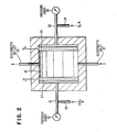
- FIG. 2 shows a fuel cell incorporating the porous electrode 21 of FIG. 1.1.
- FIG. 2 shows an oxygen- hydrogen fuel cell which incorporates a set of porous gas fed electrodes 21 and 21', and gas source 33 of hydrogen in the case of cathode electrode 21' which passes through line 32 to electrode 21'.
- Oxygen passes through line 30 from source 29 to electrode 21, and its pressure is measured by gauge 34.
- the fuel such as hydrogen, formic acid, methanol or formaldehyde passes through from source 33 to input line 32 to the electrode 21' and pressure is measured by the gauge 35.
- the alkaline electrolyte (which may contain NaOH or KOH solution) and the catalyst metal in accordance with this invention may also carry the above fuels (in which case line 32 can be eliminated) and are introduced via electrolyte inlet line 37 into the electrolyte chamber 38.
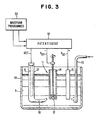
- FIG. 3 shows an experimental system which can be employed for the purpose of testing the efficacy of the instant invention in a particular embodiment.
- the apparatus of FIG. 3 is for performing measurements under conditions of controlled mass transport with the rotating disk technique. This system is described in some detail in our above-mentioned European application. The teaching thereof is incorporated herein by reference.
- Tubes 13 supply a gas to the system which will be oxygen in the case of hydrogen-oxygen fuel cells and will be nitrogen gas when using carbonaceous fuels.
- the electrolyte solution 9 comprises one to ten MOLES/liter of NaOH or KOH as the basic electrolyte with 1/100,000 MOLES/liter of platinum as the catalytic metal.
- the solutions are deoxygenated prior to taking measurements. No oxygen is supplied at inlet 13.
- Potential control of the working electrode is achieved with the potentiostat 19.
- the catalytic activity of a particular system, e.g., Pt/Au is determined by obtaining polarization curves, for say oxygen gas reduction when oxygen gas is the fuel and for the anodic oxidation of carbonaceous fuels.
- FIG. 4 shows another fuel cell in accordance with this invention which is developed from our application 83104962.2.
- the fuel cell 60 includes a cathode chamber 62 for oxygen gas supplied at inlet 61 and exhausted from chamber 62 at vent 63.
- the cathode 64 forms the left wall of the cathode chamber 62 and the oxygen gas can pass from the chamber 62 through the porous cathode 64 into the electrolyte chamber 65 which houses the liquid electrolyte which comprises NaOH or KOH solution as above.
- means are provided for refreshing the electrolyte by means such as those shown in connection with FIG. 2.
- the electrolyte in chamber 65 contacts the inner wall of cathode 64.
- the cathode 64 is a thin flat sheet of a porous material such as compressed graphite or RB carbon.
- 10 -4 or 10 -5 moles of ions of the UPD species is added to the electrolyte.
- a porous electrode 66 forms the other wall of the electrolyte chamber 65 on the opposite side of chamber 65 from the cathode 64.
- Anode 66 is also preferably metallic and dimensionally stable.
- the lower surface of the electrolyte chamber 65 is provided by base 56 which is composed of a non-corrosive material.
- the other surface of the anode 66 defines a wall of another chamber comprising the anode chamber 67.
- Chamber 67 receives a fuel supply via inlet 68 selected from the group consisting of hydrocarbons, e.g., alcohols such as methanol; aldehydes such as formaldehyde; acids such as formic acid; and hydrogen.
- the fuels are dissolved in a solution of NaOH or KOH of 1-10 moles/liter and 1 to 2 moles of fuel per liter in either the gaseous or the liquid form.
- Fuel is supplied at inlet 68 to chamber 67.
- Exhaust products consisting of C0 2 , H 2 0 and other byproducts of the oxidation-reduction process are exhausted from chamber 67 by line 69.
- a pump drives the fluids from inlet 68 into chamber 67 and out through outlet 69.
- the catalyst of FIG. 1.3 is located within the cathode 64.
- the catalyst reduces the 0 2 which combines with H 2 0 to form negative OH ions or radicals.
- the gold islands are coated with the monolayers or submonolayers of Pt, Pd, Ag, Rh or Ir which operate to enhance the operation of the fuel cell in accordance with this invention.
- the upper curve shows the superior performance for Pt on Au and the lower curve shows the results for an electrode of Au without the layer of Pt. While similar results would be obtained for a multilayer film of Pt, the life would be limited due to adsorbed impurities, and also loss of catalyst via dissolution in the electrolyte and loss of surface area via Ostwald ripening.
- Metals such as silver and platinum have been found to be useful as catalysts for the electro reduction of oxygen in aqueous electrolytes when deposited on a substrate in a dispersed form. Usually, however, these metals have such a high degree of solubility in the electrolyte that they are lost due to increased particle size (known as Ostwald ripening), total loss of catalyst from the oxygen cathode, and contamination of the anode surface with the cathode catalyst.
- Applications of this technology which have manifested this problem include petrochemical manufacturing processes such as hydrogenation and dehydrogenation, fuel cells, batteries and industrial electrolysis.
- such catalytic metals are used for oxygen reduction with monolayers or submonolayers deposited on a substrate composed of a very noble metal such as gold or an appropriate alloy.
- Layers of a catalytic metal deposited at an underpotential are much more noble (usually measured to be more than several tenths of a volt more noble) because of their interaction with the substrate.
- the deposition of the catalytic metallic monoatomic layer should occur under anodic electrical conditions in the electrochemical system relative to the operating potential of the oxygen operating cathode.
- Such conditions obtain when the atomic film comprises platinum on gold, silver on gold, or Pd, Ir or Rh on gold.
- the feasibility of this approach for oxygen catalysis has been demonstrated by experimental work with platinum on gold and silver on gold.
- a method of achieving this result is to introduce the cations of the catalytic metal into the electrolyte as an additive to form deposit of a monoatomic layer of the catalytic metal at an underpotential. This can be done while the electrode is operating to provide oxygen reduction, or in the alternative it can be performed in a separate solution prior to application of the system to useful operation. In any event, the catalytic activity of the system as measured by its lifetime, output power and efficiency are enhanced to a marked degree.
- the catalytic monolayers deposited at an underpotential are carried on a substrate comprising a stable support which is electronically conductive.
- the substrate comprises gold or its alloys. It is more stable in the sense that as follows: 1) It is refurbishable; 2) the Au crystallites are bonded to the substrates and the UPD species site on top of the upper surface of the substrates and the crystallites of Au acting as substrates are unable to travel along the surface of their substrate in that (a) they are bonded to their substrate of carbon particles, (b) protection by the UPD layer of the catalyst metal, and 3) crystallites of the UPD catalyst metals do not form because the potential is too noble using underpotential deposition as the means of forming the UPD layer, by definition.
- an oxygen molecule has one of its oxygen atoms attached to the substrate of a gold crystallite and the other oxygen atom is attached to an adsorbed adatom of Pt or another UPD catalyst atom deposited on the substrate.
- UPD species of Pt, Ir, Ag, Rh, Tl, and Pd are in a concentration of 10 -5 molar to 10 -4 molar in an alkaline electrolyte of 1 to 15 molar solution of NaOH or KOH.
- the layer of the catalyst metal on the substrate is preferably a monolayer in order to achieve the marked advantages of this invention since the bulk or thicker thin films of these metals are not catalytically active towards the oxygen gas reduction or the anodic oxidation of carbonaceous fuels.
Landscapes
- Chemical & Material Sciences (AREA)
- Engineering & Computer Science (AREA)
- Electrochemistry (AREA)
- Chemical Kinetics & Catalysis (AREA)
- Materials Engineering (AREA)
- General Chemical & Material Sciences (AREA)
- Sustainable Energy (AREA)
- Sustainable Development (AREA)
- Manufacturing & Machinery (AREA)
- Life Sciences & Earth Sciences (AREA)
- Metallurgy (AREA)
- Organic Chemistry (AREA)
- Inert Electrodes (AREA)
- Catalysts (AREA)
Abstract
Description
- The present invention relates to electrolytic cells and more particularly to systems such as fuel cells, batteries, industrial electrolysis equipment and the like.
- United States patent No. 4,192,907 of Jalan et al for "Electrochemical Cell Electrodes Incorporating Noble Metal - Base Metal Alloy Catalysts" suggests a fuel cell with a substrate of an electrically conductive material coated with a platinum base alloy. Preferably the alloy is coated on a substrate comprising conductive particles of carbon. This electrode deteriorates because of the segregation of the component elements in the alloy on the surface of the alloy with small clusters of each of the elements from the alloy forming on the surface of the alloy. Whereas Pt alone is a catalyst, the refractory metal added by Jalan et al to the Pt to form the alloy is ineffective (when isolated into islands or when in the bulk form) as a catalyst. That is, the refractory metal affords little or no catalytic activity. In addition, the Jalan et al alloy would be less expensive than Pt alone which is an important reason for trying to use it, but its life would not be extended beyond the life of Pt because of segregation and impurities. The impurities referred to are unwanted species deposited on the catalyst from the bath.
- It is known that a layer deposited at an underpotential referred to hereinafter as an underpotential deposited layer alters the electronic properties of the deposited metal making it more noble than the bulk metal, based on material published in a review article written by D. M. Kolb, published in Advances in Electrochemistry and Electrochemical Engineering, Vol. 11, Gerischer and Tobias, Eds., Interscience (1977), 125-271, especially pages 234-239. There was no suggestion that the subject matter of the article could be used as a catalyst in the way described in this application.
- Lead has been deposited on gold by underpotential deposition as described by McIntyre, et al, "Electrochemical Catalysis by Foreign Metal Adatoms", Abstract 339, Electrochemical Society pages 864-5 (1979). However, this was not done in connection with a catalyst for an electrolytic cell.
- Copper was employed on gold in an alkaline solution, as described in Amadelli, Bindra, Khutornoi and Yeager, "Influence of Metal Ions on the 02 Reduction of Noble Metals in Alkaline Solutions", Extended Abstracts of the ECS Spring Meeting, (1979) Boston, Mass.
- Recent advances in the search for new oxygen reduction electrocatalysts has led to the use of UPD monolayers of metals deposited at an underpotential to produce electrocatalytic surfaces of substantially enhanced activity and stability. See Khutornoi et al supra, and McIntyre et al supra. Formation of a UPD layer alters both the geometric structure of the surface as well as the electronic properties of the deposited metal rendering it more noble than the bulk metal. See Kolb et al supra. The electronic properties of the deposited metal are often quite specific to the UPD layer in combination with a specific substrate. Thus these modified electrodes also provide rather convenient and useful model systems for studying the correlations between the catalytic behavior and the surface electronic and geometric structure.
- The electrocatalytic activity of several UPD systems for the reduction of oxygen gas in alkaline and acid media has been examined by McIntyre et al supra and the work of Amadelli, Molla, Bindra, and Yeager, J. Electrochem. Soc., supra, in the alkaline case; and Bindra, Clouser et al in the acid case. There is an apparent anomaly in the behavior of the UPD layers in the two media. In an alkaline solution, the diffusion limiting current for oxygen reduction on gold in the presence of UPD layers of metals such as Tl, Pb (McIntyre et al supra) and copper (Amadelli et al supra) is almost doubled, indicating a favoring of the four electron reduction. Where there is an electrode surface of gold covered with a UPD layer of a catalytic metal, the result is that the equation of the chemical reaction involved is as follows:


- The net effect of this is that we have observed that twice as much power can be realized per oxygen molecule.
- Even on Pt substrates, oxygen reduction current in alkaline solution has been shown to increase in the presence of trace quantities of Tl positive ions in the electrolyte as described by Amadelli, Bindra, and Yeager, supra.
- In acid media, on the other hand, the UPD of copper seems to lower the catalytic activity of Pt for oxygen reduction as described in Bindra, Clouser et al supra. In an effort to understand the anomalous behavior, the catalytic effects of UPD layers on oxygen reduction have been examined in weakly acidic, neutral, and alkaline electrolyte.
- Lead has been deposited on mercury or gold in a neutral medium (pH of about 7) in the form of a UPD layer of lead on mercury and lead on gold in a paper by Bindra, "The Effect of pH on the Electrocatalytic Properties of Adsorbed Metal Ions", Journal of the Electrochemical Society (submitted 1982).
- Lead or thallium on gold has been published by Amadelli et al "Influence of Metal Ions on the 02 Reduction of Noble Metals in Alkaline Solutions", Journal of the Electrochemical Society, Vol. 128, No. 12, pages 2706-2709 (Dec. 1981).
- This invention is believed to differ from the prior art.
- Preferably, the system of this invention utilizes an element selected from the groups consisting of:
- a) Pt, Ir, Pd, Ag, or Rh as a catalyst in alkaline media and to control impurities in any media, or
- b) Pb, Tl or Bi as a catalyst in alkaline media or as a means to control impurities in acid media on thin crystallites of Au. They are distinguished from the above systems in that the substrate is particulate and some of the adsorbates are noble metals. In the above systems the adsorbate is a base metal such as lead.
- Another preferred aspect of this invention resides in the novel feature of using a catalyst such as Pt rather than Pb where the Pb would poison one of the electrodes in the electrochemical system. That statement is qualified by the fact that a diaphragm between electrodes in the system could be used to avoid poisoning, but that the cost of such a solution would be reduced voltage. It should be understood that as a catalyst alone, Pb is effective in those cases in which it would not tend to poison the electrodes.
- Small crystallites of gold and a monolayer of a UPD catalyst metal in solution provide a) a high surface area, b) the UPD layer can stay only on the surface of the substrate metal (gold) since the substrate metal is too thin or not bulky enough for the catalyst layer to diffuse into the bulk (i.e., thick film metal).
- UPD metal catalysts in this environment control the buildup of impurities on the surface of the catalyst which is not described in any of the above references. Here we refer to metals such as Pt, Pd, Ag, Rh, Ir, as well as Pb, Tl, and Bi in the case of acid media (electrolytes).
- In accordance with this invention, the problems of limited lifetime of the catalyst caused by loss of catalyst coupled with reduction of economic viability of the system are dealt with.
- It is desired to form superior fuel cell catalysts which are efficient, long-lived, and refurbishable in-situ.
- In addition, it is an object of this invention to achieve greater output efficiency or power for a given input of fuel.
- We have discovered for example that the presence of UPD Ag, Pt, Pd, Ir, Rh on Au crystallites carried on and bonded to another substrate causes dissociative adsorption of the oxygen molecules so that four electrons are produced per molecule during the reduction reaction which is involved. This is superior to the gold surface which fails to dissociate the oxygen molecules, so that only two electrons are realized per oxygen molecule. In addition, for an alkaline electrolyte, the catalyst metals such as Pd, Ir, Ag, Rh and Pt show no tendency to poison the counter electrode (counter relative to the other electrode) since each of those metals is a good catalyst for both electrodes. In contrast we have found that Pb on Au poisons the hydrogen electrode.
- The oxygen gas molecule undergoes dissociative adsorption on the surface of the catalyst. Oxygen is reduced to hydroxyl ions and in the absence of the UPD monolayer, the oxygen and water are converted to hydrogen peroxide.
- The above-described systems can operate with several different fuels. They include use of methanol ((CH30H), formaldehyde (HCHO), and formic acid (HCOOH).
- The foregoing and other objects, features and advantages of the invention will be apparent from the more particular description of the preferred embodiments of the invention, as illustrated in the accompanying drawings.
-
- FIG. 1.1 shows an electrode, usable in a fuel cell in accordance with this invention, in the form of a support for numerous microscopic carbon. particles each of which carries a plurality of smaller gold crystallites in the form of tiny islands. FIG. 1.2 shows a single particle of carbon from FIG. 1.1 enlarged in size with the crystallites of gold seen on the surface.
- FIG. 1.3 shows a single crystallite of gold from FIG. 1.2 with a monolayer of a catalyst metal deposited on the surface of the gold crystallite in accordance with this invention.
- FIG. 2 shows a fuel cell incorporating a porous electrode of the variety shown in FIGS. 1.1-1.3.
- FIG. 3 shows an experimental electrochemical system for testing the efficacy of the instant invention.
- FIG. 4 shows another form of fuel cell adapted for use in accordance with this invention, with an electrolyte chamber between two chambers for oxygen and fuel respectively.
- FIG. 5 shows a graph of current vs potential for oxygen reduction in an electrolyte in accordance with this invention.
- In the drawings, like elements are designated with similar reference numbers, and identical elements in different specific embodiments are designated by identical reference numbers.
- FIG. 1.1 shows a support for a set of
carbon particles 23 each of which carries numerous small gold islands upon which are deposited a monolayer of the catalyst particles of this invention as will be described in detail below in connection with FIG. 1.2. FIG. 1.1 shows a stationary porous, gas fed, carbon andmetal screen electrode 21 which can be employed as a working electrode in an electrolytic cell in accordance with this invention. Theporous electrode 21 is shown with aporous substrate 22 of Teflon polytetrafluoroethylene which carries an amalgam of smallcompressed carbon particles 23 supported upon a matrix ofmetallic wires 24 which are woven into a screen.Wires 24 are composed of a metal such as nickel. Thewires 24 connect to a lead of a DC source (as described in our European application 83109324.0) to provide an attractive force to the metallic gold ions in anelectrolyte 9 in FIG. 3, which causes them to be deposited on the myriad surfaces of thecarbon particles 23 both on the interior and the exterior of theelectrode 21. Prior to application of chemical deposition pulses from a programmer, the electrolyte preferably comprises as follows:
- The solution carries ions of the gold to deposit to form the gold islands. Prior to deposition of the gold islands on the carbon, the electrolyte is permitted to diffuse within the
porous electrode 21, which is adapted to be used as an electrode in a fuel cell or another form of electrochemical cell.Porous electrode 21 is suitable for use as a gas fed electrode such as those shown in FIGS. 2 and 4, where gas is fed throughelectrode electrolyte - FIG. 1.2 shows a
particle 25 ofcarbon 23 enlarged from a microscopic size which has been plated with numeroussmall crystallites 26 of gold forming the myriad substrates upon which the catalyst metal can deposit the monolayers or submonolayers of this invention.Crystallites 26 are spread widely over the surface of eachmicroscopic carbon particle 25. Thecrystallites 26 are about 5-10 nm in diameter and about two to ten atomic layers thick giving surface areas of about 100 square meters per gram. - FIG. 1.3 shows a
single crystallite 26 of gold coated with a monolayer of a catalyst metal in accordance with this invention comprising a metal such as platinum, silver, palladium, iridium, or rhodium. FIG. 2 shows a fuel cell incorporating theporous electrode 21 of FIG. 1.1. FIG. 2 shows an oxygen- hydrogen fuel cell which incorporates a set of porous gas fedelectrodes 21 and 21', andgas source 33 of hydrogen in the case of cathode electrode 21' which passes throughline 32 to electrode 21'. Oxygen passes throughline 30 fromsource 29 toelectrode 21, and its pressure is measured bygauge 34. The fuel such as hydrogen, formic acid, methanol or formaldehyde passes through fromsource 33 to inputline 32 to the electrode 21' and pressure is measured by thegauge 35. The alkaline electrolyte (which may contain NaOH or KOH solution) and the catalyst metal in accordance with this invention may also carry the above fuels (in whichcase line 32 can be eliminated) and are introduced viaelectrolyte inlet line 37 into theelectrolyte chamber 38. - FIG. 3 shows an experimental system which can be employed for the purpose of testing the efficacy of the instant invention in a particular embodiment. The apparatus of FIG. 3 is for performing measurements under conditions of controlled mass transport with the rotating disk technique. This system is described in some detail in our above-mentioned European application. The teaching thereof is incorporated herein by reference.
- Fabrication of the rotating disk electrodes has been described by J P Randin and E Yeager, J. Electroanal. Chem. Interfacial Electrochem. 36 (1972) 257. After fabrication, the ordinary
pyrolytic graphite electrode 12 serving as a working electrode was polished nearly to a mirror finish. Thecounter electrode 15 was composed of platinum foil and the reference electrode 16 was a saturated calomel electrode (SCE). The electrochemical cell used was a standard laboratory type with aseparate compartment 17 for the reference electrode 16. The reference electrode is separated from the workingelectrode compartment 10 by afrit 18.Potentiostat 19 powers the electrodes with awaveform programmer 20. -
Tubes 13 supply a gas to the system which will be oxygen in the case of hydrogen-oxygen fuel cells and will be nitrogen gas when using carbonaceous fuels. Theelectrolyte solution 9 comprises one to ten MOLES/liter of NaOH or KOH as the basic electrolyte with 1/100,000 MOLES/liter of platinum as the catalytic metal. When using carbonaceous fuels, the solutions are deoxygenated prior to taking measurements. No oxygen is supplied atinlet 13. Potential control of the working electrode is achieved with thepotentiostat 19. The catalytic activity of a particular system, e.g., Pt/Au is determined by obtaining polarization curves, for say oxygen gas reduction when oxygen gas is the fuel and for the anodic oxidation of carbonaceous fuels. - FIG. 4 shows another fuel cell in accordance with this invention which is developed from our application 83104962.2. The teachings of that application are incorporated herein by reference. The
fuel cell 60 includes acathode chamber 62 for oxygen gas supplied atinlet 61 and exhausted fromchamber 62 atvent 63. Thecathode 64 forms the left wall of thecathode chamber 62 and the oxygen gas can pass from thechamber 62 through theporous cathode 64 into theelectrolyte chamber 65 which houses the liquid electrolyte which comprises NaOH or KOH solution as above. Preferably, means are provided for refreshing the electrolyte by means such as those shown in connection with FIG. 2. The electrolyte inchamber 65 contacts the inner wall ofcathode 64. As in FIG. 1.1, thecathode 64 is a thin flat sheet of a porous material such as compressed graphite or RB carbon. - Preferably, 10-4 or 10-5 moles of ions of the UPD species is added to the electrolyte.
- A
porous electrode 66 forms the other wall of theelectrolyte chamber 65 on the opposite side ofchamber 65 from thecathode 64.Anode 66 is also preferably metallic and dimensionally stable. The lower surface of theelectrolyte chamber 65 is provided bybase 56 which is composed of a non-corrosive material. The other surface of theanode 66 defines a wall of another chamber comprising theanode chamber 67.Chamber 67 receives a fuel supply via inlet 68 selected from the group consisting of hydrocarbons, e.g., alcohols such as methanol; aldehydes such as formaldehyde; acids such as formic acid; and hydrogen. The fuels are dissolved in a solution of NaOH or KOH of 1-10 moles/liter and 1 to 2 moles of fuel per liter in either the gaseous or the liquid form. Fuel is supplied at inlet 68 tochamber 67. Exhaust products consisting of C02,H 20 and other byproducts of the oxidation-reduction process are exhausted fromchamber 67 byline 69. A pump drives the fluids from inlet 68 intochamber 67 and out throughoutlet 69. - The catalyst of FIG. 1.3 is located within the
cathode 64. The catalyst reduces the 02 which combines withH 20 to form negative OH ions or radicals. The gold islands are coated with the monolayers or submonolayers of Pt, Pd, Ag, Rh or Ir which operate to enhance the operation of the fuel cell in accordance with this invention. - FIG. 5 shows the current vs potential curve for oxygen reduction in 1 molar sodium hydroxide plus 1/100,000 Pt(S04)2 at 2500 rpm dv/dt=15 mv/sec and area=0.2cm , at 25 degrees C. The upper curve shows the superior performance for Pt on Au and the lower curve shows the results for an electrode of Au without the layer of Pt. While similar results would be obtained for a multilayer film of Pt, the life would be limited due to adsorbed impurities, and also loss of catalyst via dissolution in the electrolyte and loss of surface area via Ostwald ripening.
- Metals such as silver and platinum have been found to be useful as catalysts for the electro reduction of oxygen in aqueous electrolytes when deposited on a substrate in a dispersed form. Usually, however, these metals have such a high degree of solubility in the electrolyte that they are lost due to increased particle size (known as Ostwald ripening), total loss of catalyst from the oxygen cathode, and contamination of the anode surface with the cathode catalyst. Applications of this technology which have manifested this problem include petrochemical manufacturing processes such as hydrogenation and dehydrogenation, fuel cells, batteries and industrial electrolysis.
- In accordance with this invention, such catalytic metals are used for oxygen reduction with monolayers or submonolayers deposited on a substrate composed of a very noble metal such as gold or an appropriate alloy. Layers of a catalytic metal deposited at an underpotential are much more noble (usually measured to be more than several tenths of a volt more noble) because of their interaction with the substrate. It is necessary that the deposition of the catalytic metallic monoatomic layer should occur under anodic electrical conditions in the electrochemical system relative to the operating potential of the oxygen operating cathode. Such conditions obtain when the atomic film comprises platinum on gold, silver on gold, or Pd, Ir or Rh on gold. The feasibility of this approach for oxygen catalysis has been demonstrated by experimental work with platinum on gold and silver on gold.
- A method of achieving this result is to introduce the cations of the catalytic metal into the electrolyte as an additive to form deposit of a monoatomic layer of the catalytic metal at an underpotential. This can be done while the electrode is operating to provide oxygen reduction, or in the alternative it can be performed in a separate solution prior to application of the system to useful operation. In any event, the catalytic activity of the system as measured by its lifetime, output power and efficiency are enhanced to a marked degree.
- For oxygen electrodes of the gas-fed type adapted to high performance operation, the catalytic monolayers deposited at an underpotential are carried on a substrate comprising a stable support which is electronically conductive. Preferably, the substrate comprises gold or its alloys. It is more stable in the sense that as follows: 1) It is refurbishable; 2) the Au crystallites are bonded to the substrates and the UPD species site on top of the upper surface of the substrates and the crystallites of Au acting as substrates are unable to travel along the surface of their substrate in that (a) they are bonded to their substrate of carbon particles, (b) protection by the UPD layer of the catalyst metal, and 3) crystallites of the UPD catalyst metals do not form because the potential is too noble using underpotential deposition as the means of forming the UPD layer, by definition. In addition to greater stability, the approach provides the opportunity to improve the catalytic activity of the catalyst monolayer through electronic changes in its properties brought about by its interaction with the substrate. In addition, submonolayers provide an opportunity for enhancement of the catalytic effect through spill- over effects involving the substrate and the partial monolayer. For example, an oxygen molecule has one of its oxygen atoms attached to the substrate of a gold crystallite and the other oxygen atom is attached to an adsorbed adatom of Pt or another UPD catalyst atom deposited on the substrate.
- EXAMPLE The UPD species of Pt, Ir, Ag, Rh, Tl, and Pd are in a concentration of 10-5 molar to 10-4 molar in an alkaline electrolyte of 1 to 15 molar solution of NaOH or KOH.
- We have discovered that the layer of the catalyst metal on the substrate is preferably a monolayer in order to achieve the marked advantages of this invention since the bulk or thicker thin films of these metals are not catalytically active towards the oxygen gas reduction or the anodic oxidation of carbonaceous fuels.
Claims (5)
Applications Claiming Priority (2)
| Application Number | Priority Date | Filing Date | Title |
|---|---|---|---|
| US06/454,746 US4457986A (en) | 1982-12-30 | 1982-12-30 | Use of underpotential deposited layers of metals on foreign metal substrates as catalysts for electrolytic cells |
| US454746 | 1982-12-30 |
Publications (3)
| Publication Number | Publication Date |
|---|---|
| EP0117290A2 true EP0117290A2 (en) | 1984-09-05 |
| EP0117290A3 EP0117290A3 (en) | 1986-01-22 |
| EP0117290B1 EP0117290B1 (en) | 1988-10-26 |
Family
ID=23805902
Family Applications (1)
| Application Number | Title | Priority Date | Filing Date |
|---|---|---|---|
| EP83111416A Expired EP0117290B1 (en) | 1982-12-30 | 1983-11-15 | Fuel cell catalysts |
Country Status (4)
| Country | Link |
|---|---|
| US (1) | US4457986A (en) |
| EP (1) | EP0117290B1 (en) |
| JP (1) | JPH0665038B2 (en) |
| DE (1) | DE3378336D1 (en) |
Families Citing this family (19)
| Publication number | Priority date | Publication date | Assignee | Title |
|---|---|---|---|---|
| US5133842A (en) * | 1988-11-17 | 1992-07-28 | Physical Sciences, Inc. | Electrochemical cell having electrode comprising gold containing electrocatalyst |
| US5041195A (en) * | 1988-11-17 | 1991-08-20 | Physical Sciences Inc. | Gold electrocatalyst, methods for preparing it, electrodes prepared therefrom and methods of using them |
| US5132193A (en) * | 1990-08-08 | 1992-07-21 | Physical Sciences, Inc. | Generation of electricity with fuel cell using alcohol fuel |
| RU2136082C1 (en) * | 1997-11-11 | 1999-08-27 | Уральский электрохимический комбинат | Oxygen electrode catalyst for fuel cell with alkali electrolyte |
| JP2001236968A (en) * | 2000-02-23 | 2001-08-31 | Asahi Kasei Corp | Fuel cell reactor and method of using the same |
| AU2001279307A1 (en) * | 2000-07-25 | 2002-02-05 | Apollo Energy Systems, Incorporated | Additives to the gas supply of fuel cells with circulating electrolytes and means to regenerate used stacks |
| JP4721539B2 (en) * | 2001-03-26 | 2011-07-13 | パナソニック株式会社 | Fuel cell electrode catalyst and method for producing the same |
| US7132188B2 (en) * | 2002-04-04 | 2006-11-07 | The Board Of Trustees Of The University Of Illinois | Fuel cells and fuel cell catalysts |
| US7282282B2 (en) * | 2002-04-04 | 2007-10-16 | The Board Of Trustees Of The University Of Illinois | Organic fuel cells and fuel cell conducting sheets |
| US7785728B2 (en) * | 2002-04-04 | 2010-08-31 | The Board Of Trustees Of The University Of Illinois | Palladium-based electrocatalysts and fuel cells employing such electrocatalysts |
| US7740974B2 (en) | 2002-04-04 | 2010-06-22 | The Board Of Trustees Of The University Of Illinois | Formic acid fuel cells and catalysts |
| US6986957B2 (en) * | 2002-12-09 | 2006-01-17 | Motorola, Inc. | Fuel cell system |
| US20060024539A1 (en) * | 2004-07-29 | 2006-02-02 | Dumesic James A | Catalytic method to remove CO and utilize its energy content in CO-containing streams |
| US7704919B2 (en) * | 2005-08-01 | 2010-04-27 | Brookhaven Science Associates, Llc | Electrocatalysts having gold monolayers on platinum nanoparticle cores, and uses thereof |
| CN102132447B (en) * | 2008-08-25 | 2013-12-18 | 3M创新有限公司 | Fuel cell nanocatalyst with voltage reversal tolerance |
| WO2011099957A1 (en) | 2010-02-12 | 2011-08-18 | Utc Power Corporation | Platinum monolayer on hollow, porous nanoparticles with high surface areas and method of making |
| IN2012DN06287A (en) | 2010-02-12 | 2015-09-25 | Utc Power Corp | |
| US9484580B2 (en) * | 2012-06-22 | 2016-11-01 | Audi Ag | Platinum monolayer for fuel cell |
| US10497943B2 (en) | 2012-12-03 | 2019-12-03 | Audi Ag | Core-shell catalyst and method for palladium-based core particle |
Family Cites Families (10)
| Publication number | Priority date | Publication date | Assignee | Title |
|---|---|---|---|---|
| US3427153A (en) * | 1964-06-11 | 1969-02-11 | Leesona Corp | Method of preparing alloy blacks |
| US3444003A (en) * | 1965-09-30 | 1969-05-13 | Leesona Corp | Multilayer catalytic electrode having a layer of noble metal and lead and a surface layer free of lead and method of constructing same |
| NL6613162A (en) * | 1965-09-30 | 1967-03-31 | ||
| US3506494A (en) * | 1966-12-22 | 1970-04-14 | Engelhard Ind Inc | Process for producing electrical energy utilizing platinum-containing catalysts |
| US3414439A (en) * | 1967-03-13 | 1968-12-03 | Engelhard Ind Inc | Fuel cell and process of using with ruthenium-tantalum alloy catalyst |
| DE2208632C3 (en) * | 1972-02-24 | 1981-07-30 | Battelle-Institut E.V., 6000 Frankfurt | Process for the production of carbon-containing gas electrodes with a hydrophobic backing layer |
| NL7502841A (en) * | 1975-03-11 | 1976-09-14 | Stamicarbon | METHOD OF MANUFACTURING A METAL ELECTRODE. |
| US4192907A (en) * | 1978-07-03 | 1980-03-11 | United Technologies Corporation | Electrochemical cell electrodes incorporating noble metal-base metal alloy catalysts |
| US4186110A (en) * | 1978-07-03 | 1980-01-29 | United Technologies Corporation | Noble metal-refractory metal alloys as catalysts and method for making |
| US4373014A (en) * | 1980-06-18 | 1983-02-08 | United Technologies Corporation | Process using noble metal-chromium alloy catalysts in an electrochemical cell |
-
1982
- 1982-12-30 US US06/454,746 patent/US4457986A/en not_active Expired - Lifetime
-
1983
- 1983-10-20 JP JP58195367A patent/JPH0665038B2/en not_active Expired - Lifetime
- 1983-11-15 DE DE8383111416T patent/DE3378336D1/en not_active Expired
- 1983-11-15 EP EP83111416A patent/EP0117290B1/en not_active Expired
Also Published As
| Publication number | Publication date |
|---|---|
| DE3378336D1 (en) | 1988-12-01 |
| EP0117290A3 (en) | 1986-01-22 |
| EP0117290B1 (en) | 1988-10-26 |
| JPS59139569A (en) | 1984-08-10 |
| US4457986A (en) | 1984-07-03 |
| JPH0665038B2 (en) | 1994-08-22 |
Similar Documents
| Publication | Publication Date | Title |
|---|---|---|
| EP0117290B1 (en) | Fuel cell catalysts | |
| US4818353A (en) | Method for modifying electrocatalyst material, electrochemical cells and electrodes containing this modified material, and synthesis methods utilizing the cells | |
| Papaderakis et al. | Oxygen evolution at IrO2 shell–Ir− Ni core electrodes prepared by galvanic replacement | |
| US20090075139A1 (en) | Nanoporous/mesoporous palladium catalyst | |
| US6183894B1 (en) | Electrocatalyst for alcohol oxidation in fuel cells | |
| EP1341603B1 (en) | Methods and apparatus for the oxidation of glucose molecules | |
| JPH0665773A (en) | Electrocatalyst and electrocatalyst method | |
| Kleinikova et al. | Some features of alcohols electrooxidation process on Pd, Rh and PdRh catalysts | |
| US3287171A (en) | Platinum-rhenium anodic oxidation catalyst | |
| JP2009515036A (en) | Carbon fiber electrocatalyst for oxidizing ammonia and ethanol in alkaline media and its application to hydrogen production, fuel cells and purification processes | |
| Sriram et al. | Elucidation of ultrasonic wave-assisted electrodeposited AgPd nanoalloy from ionic liquid as an efficient bifunctional electrocatalyst for methanol oxidation and hydrogen peroxide reduction | |
| Li et al. | Efficient electrochemical NO reduction to NH3 over metal-free g-C3N4 nanosheets and the role of interface microenvironment | |
| Mkwizu et al. | Electrodeposition of multilayered bimetallic nanoclusters of ruthenium and platinum via surface-limited redox− replacement reactions for electrocatalytic applications | |
| TW201903209A (en) | Electrode base material, and electrode catalyst and electrolysis apparatus each using same | |
| US20030047459A1 (en) | Electrochemical reacting electrode, method of making, and application device | |
| US6224741B1 (en) | Electrolyte process using a hydrogen storing metal member | |
| CN119194493A (en) | Modification method of copper-based catalyst for electrocatalytic carbon dioxide reduction, product and application thereof | |
| US4900585A (en) | Cathode and process for the manufacture thereof | |
| US4793905A (en) | Method for partially and selectively oxidizing alcohols to esters or carboxylic acids | |
| Zinesh et al. | Recovery of radiogenic osmium-187 from sulfide copper ores in Kazakhstan | |
| Foise et al. | Use of colloidal ruthenium particles in the electrochemical reduction of benzene by solvated electrons | |
| Lucero | Design of Palladium Alloy Electrolytic Separators for GC-MS Analysis Systems | |
| US20110008715A1 (en) | Platinum loaded substrate for a fuel cell and method for producing same | |
| Saad et al. | Nickel and titanium metals for the hydrogen evolution reaction in water electrolysis: A comparative study | |
| Shrestha | Hierarchical Hybrid Electrodes Composed of Carbon Nanotube Carpets with Palladium Nanoparticles Covalently Bonded to Porous Carbon Substrates for Electrochemical Applications |
Legal Events
| Date | Code | Title | Description |
|---|---|---|---|
| PUAI | Public reference made under article 153(3) epc to a published international application that has entered the european phase |
Free format text: ORIGINAL CODE: 0009012 |
|
| AK | Designated contracting states |
Designated state(s): DE FR GB |
|
| 17P | Request for examination filed |
Effective date: 19841029 |
|
| PUAL | Search report despatched |
Free format text: ORIGINAL CODE: 0009013 |
|
| AK | Designated contracting states |
Designated state(s): DE FR GB |
|
| 17Q | First examination report despatched |
Effective date: 19861015 |
|
| GRAA | (expected) grant |
Free format text: ORIGINAL CODE: 0009210 |
|
| AK | Designated contracting states |
Kind code of ref document: B1 Designated state(s): DE FR GB |
|
| REF | Corresponds to: |
Ref document number: 3378336 Country of ref document: DE Date of ref document: 19881201 |
|
| ET | Fr: translation filed | ||
| PLBE | No opposition filed within time limit |
Free format text: ORIGINAL CODE: 0009261 |
|
| STAA | Information on the status of an ep patent application or granted ep patent |
Free format text: STATUS: NO OPPOSITION FILED WITHIN TIME LIMIT |
|
| 26N | No opposition filed | ||
| PGFP | Annual fee paid to national office [announced via postgrant information from national office to epo] |
Ref country code: GB Payment date: 19931019 Year of fee payment: 11 |
|
| PGFP | Annual fee paid to national office [announced via postgrant information from national office to epo] |
Ref country code: FR Payment date: 19931103 Year of fee payment: 11 |
|
| PGFP | Annual fee paid to national office [announced via postgrant information from national office to epo] |
Ref country code: DE Payment date: 19931118 Year of fee payment: 11 |
|
| PG25 | Lapsed in a contracting state [announced via postgrant information from national office to epo] |
Ref country code: GB Effective date: 19941115 |
|
| GBPC | Gb: european patent ceased through non-payment of renewal fee |
Effective date: 19941115 |
|
| PG25 | Lapsed in a contracting state [announced via postgrant information from national office to epo] |
Ref country code: FR Effective date: 19950731 |
|
| PG25 | Lapsed in a contracting state [announced via postgrant information from national office to epo] |
Ref country code: DE Effective date: 19950801 |
|
| REG | Reference to a national code |
Ref country code: FR Ref legal event code: ST |