EP0117153A1 - Apparatus for forming an explosively expanded tube-tube sheet joint including a fibre reinforced insert having a closed end - Google Patents
Apparatus for forming an explosively expanded tube-tube sheet joint including a fibre reinforced insert having a closed end Download PDFInfo
- Publication number
- EP0117153A1 EP0117153A1 EP19840301110 EP84301110A EP0117153A1 EP 0117153 A1 EP0117153 A1 EP 0117153A1 EP 19840301110 EP19840301110 EP 19840301110 EP 84301110 A EP84301110 A EP 84301110A EP 0117153 A1 EP0117153 A1 EP 0117153A1
- Authority
- EP
- European Patent Office
- Prior art keywords
- tube
- force
- transmitting member
- explosive
- tube sheet
- Prior art date
- Legal status (The legal status is an assumption and is not a legal conclusion. Google has not performed a legal analysis and makes no representation as to the accuracy of the status listed.)
- Granted
Links
- 239000000835 fiber Substances 0.000 title claims 3
- 239000002360 explosive Substances 0.000 claims abstract description 41
- 239000007789 gas Substances 0.000 claims abstract description 11
- 238000004880 explosion Methods 0.000 claims abstract description 10
- 239000000463 material Substances 0.000 claims description 4
- 239000002657 fibrous material Substances 0.000 abstract description 7
- 239000004033 plastic Substances 0.000 abstract description 3
- 229920003023 plastic Polymers 0.000 abstract description 3
- 239000012530 fluid Substances 0.000 description 6
- 238000000034 method Methods 0.000 description 4
- 230000035939 shock Effects 0.000 description 3
- 238000005474 detonation Methods 0.000 description 2
- ZOXJGFHDIHLPTG-UHFFFAOYSA-N Boron Chemical compound [B] ZOXJGFHDIHLPTG-UHFFFAOYSA-N 0.000 description 1
- OKTJSMMVPCPJKN-UHFFFAOYSA-N Carbon Chemical compound [C] OKTJSMMVPCPJKN-UHFFFAOYSA-N 0.000 description 1
- 239000004698 Polyethylene Substances 0.000 description 1
- 229910052796 boron Inorganic materials 0.000 description 1
- 239000011152 fibreglass Substances 0.000 description 1
- 229910002804 graphite Inorganic materials 0.000 description 1
- 239000010439 graphite Substances 0.000 description 1
- 239000002184 metal Substances 0.000 description 1
- 238000012986 modification Methods 0.000 description 1
- 230000004048 modification Effects 0.000 description 1
- 238000005192 partition Methods 0.000 description 1
- -1 polyethylene Polymers 0.000 description 1
- 229920000573 polyethylene Polymers 0.000 description 1
- 230000001681 protective effect Effects 0.000 description 1
- 238000005096 rolling process Methods 0.000 description 1
- 238000006467 substitution reaction Methods 0.000 description 1
Images
Classifications
-
- B—PERFORMING OPERATIONS; TRANSPORTING
- B23—MACHINE TOOLS; METAL-WORKING NOT OTHERWISE PROVIDED FOR
- B23K—SOLDERING OR UNSOLDERING; WELDING; CLADDING OR PLATING BY SOLDERING OR WELDING; CUTTING BY APPLYING HEAT LOCALLY, e.g. FLAME CUTTING; WORKING BY LASER BEAM
- B23K20/00—Non-electric welding by applying impact or other pressure, with or without the application of heat, e.g. cladding or plating
- B23K20/06—Non-electric welding by applying impact or other pressure, with or without the application of heat, e.g. cladding or plating by means of high energy impulses, e.g. magnetic energy
- B23K20/08—Explosive welding
- B23K20/085—Explosive welding for tubes, e.g. plugging
Definitions
- This invention relates to an apparatus for explosively forming a tube-tube sheet joint and, more particularly, to such an apparatus utilizing an explosive which is placed within the tube to be expanded.
- heat exchangers feature the use of a plurality of heat exchange tubes disposed within a tube sheet and adapted to receive a primary fluid which is passed through the tubes in a heat exchange relationship with a secondary fluid passing over the tubes.
- the tubes have been mechanically expanded into the tube sheets utilizing a mandrel or the like, or by rolling, i.e., by applying an outward radial force against the entire surface of the tubes.
- these techniques enjoy several disadvantages including local metal deformation, general lengthening of the tubes, and the application of axial stresses on the tube weld and compressive strains in the tube wall.
- an explosive charge is disposed within the area of overlap between the tubes and the tube sheet and is surrounded by a force transmitting member which, upon detonation of the explosive charge, expands the- tube uniformly against the inner wall of the tube sheet.
- an explosive is disposed within each tube coextensive with that portion of the tube to be expanded.
- a force-transmitting member is disposed between the explosive and each tube and contains a longitudinally extending fiber material to strengthen the latter member. The end portion of the force-transmitting member adjacent the inner surface of the tube sheet is closed so that it contains the debris and gases associated with the explosion of the explo- sive.
- the reference numeral 10 refers in general to a tube sheet which can form a portion of a heat exchanger having a plurality of heat exchange tubes, one of which is shown by the reference numeral 12.
- the outer diameter of the tube 12 is slightly less than than the inner diameter of the tube sheet bore and the tube may be secured to the tube sheet 10 by an annular weldment 14 which welds the flush end of the tube to the outer surface of the tube sheet. Only a portion of the tube 12 is shown in the interest of clarity, it being understood that the heat exchanger would also include a vessel enclosing the tube sheet and having suitable inlets and outlets for a primary heat exchange fluid and a secondary heat exchange fluid. According to a typical arrangement of this type, the tubes 12 could be U-shaped with both ends of each tube extending through the tube sheet 10 and the heat exchanger would include a partition, or the like.
- the primary heat exchange fluid would enter the tubes 12 through one end from an area to the left of the tube sheet 10 as viewed in Fig. 1, pass through the tubes in a heat exchange relation with the secondary fluid passing through the vessel to the right of the tube sheet, and exit through the other ends of the tubes.
- the tube 12 is depicted in Fig. 1 prior to it being explosively formed in the tube sheet 10, along with the apparatus of the present invention for effecting the explosive forming.
- the latter apparatus includes an insert, shown in general by the reference numeral 18, which extends within the tube 12 and consists of a generally tubular force-transmitting member 20 and a rod-shaped explosive member 22 extending within the bore of the tubular member.
- the tubular member 20 has an outside diameter which is slightly less than the inner diameter of the tube 12, and a shoulder 23 is provided on the end of the tubular member which engages the weldment 14 to precisely locate the tubular member 20, and therefore the entire insert 18, within the tube 12.
- the length of the tubular member 20 is such that, when positioned within the tube as shown, it extends substantially coextensive with the area of overlap between the tube 12 and tube sheet 10.
- the end portion of the tubular member 20 extending adjacent the inner surface of the tube sheet 10 is closed, as shown by the reference numeral 20a.
- the explosive member 22 is disposed within the bore of the tubular member 20 intermediate the ends thereof and contains a predetermined number of grains of explosive distributed uniformly along its axis.
- the bore of the tubular member 20 extending between its closed end portion 20a and the corresponding end portion of the explosive member 22 is enlarged to form an inner cavity, or chamber, 23.
- a detonator cap 24 is provided externally of the tube sheet 10 and contains a very sensitive primary explosive which detonates readily when set off by a primer, an electrical blast cap, or the like, in a conventional manner.
- An energy transfer cord 26 connects the detonator cap 24 with the insert 18, and contains a relatively low number of grains of explosive, surrounded by a protective sheath preferably of a plastic material. The-relative size of the sheath when compared to the explosive potential of the explosives of the cord 26 is such that the sheath will contain the debris and gases resulting from the explosion as will be described in detail later. Further details of the energy transfer cord 26 are disclosed in copending patent application Serial No. (attorney's docket no. 16,429A - USD 1842A) filed November 15, 1982, and assigned to the same assignee as the present application.
- a counter-bore 32 is formed in the tubular member 20 for receiving a booster 34, with the outer surface of the booster 34 extending flush with the member 20 and connected to the other end of the energy transfer cord 26.
- the other end of the booster 34 is formed with a relatively small cavity-in which an explosive is disposed, with the booster being positioned so that the explosive does not fall outside of the axial location of the tube sheet 10. It is noted that the corresponding end of the explosive member 22 is slightly spaced from the latter end portion of the booster 34.
- a fiber material 40 is embedded in the force-transmitting member 20 and extends longitudinally for the length of the latter member.
- the fiber material 40 may be in the form of a continuous filament or may be in the form of a plurality of individual filaments. In either case, the sections or strands of the fiber material extends in a fairly closely spaced relationship as shown in Fig. 2.
- the force-transmitting member 20 is formed of polyethylene and the fiber material 40. is in the form of fiberglass, graphite or boron.
- the booster 34 is detonated by the energy transfer cord 26 which, in turn, detonates the explosive member 22, with the resulting forces being transmitted, via the force-transmitting member, uniformly to the tube 12 to cause a uniform expansion of the tube against the wall portion of the tube sheet 10 forming the corresponding tube-receiving bore.
- the booster 34 is necessary since, in order to properly contain the debris and gases resulting from the detonation of the energy transfer cord 26, the amount of . explosives contained in the latter cord must be kept below that which is necessary to directly detonate the explosive member 22.
- the presence of the closed end portion 20a of the tubular member.20 contains the debris and gases resulting from the explosion within the cavity 23 and thus prevents their escape past the inner surface of the tube sheet 10.
Landscapes
- Engineering & Computer Science (AREA)
- Mechanical Engineering (AREA)
- Pressure Welding/Diffusion-Bonding (AREA)
- Manufacture Of Alloys Or Alloy Compounds (AREA)
Abstract
Description
- This invention relates to an apparatus for explosively forming a tube-tube sheet joint and, more particularly, to such an apparatus utilizing an explosive which is placed within the tube to be expanded.
- Many current designs of heat exchangers feature the use of a plurality of heat exchange tubes disposed within a tube sheet and adapted to receive a primary fluid which is passed through the tubes in a heat exchange relationship with a secondary fluid passing over the tubes.
- Various techniques have evolved for securing the tubes within the tube sheet. For example, the tubes have been mechanically expanded into the tube sheets utilizing a mandrel or the like, or by rolling, i.e., by applying an outward radial force against the entire surface of the tubes. However, these techniques enjoy several disadvantages including local metal deformation, general lengthening of the tubes, and the application of axial stresses on the tube weld and compressive strains in the tube wall.
- In order to overcome the foregoing disadvantages, a technique of explosively forming the tubes within the tube sheet has evolved. According to this technique, an explosive charge is disposed within the area of overlap between the tubes and the tube sheet and is surrounded by a force transmitting member which, upon detonation of the explosive charge, expands the- tube uniformly against the inner wall of the tube sheet.
- One problem associated with this type of explosive forming is the possibility of breakup due to longitudinal shock waves of the force-transmitting member. Also the gases and debris resulting from the explosion come out of the end of the force-transmitting member located adjacent the inner face of the tube sheet, which are unacceptable in many industrial applications, not the least of which is in connection with nuclear heat exchanger explosive expansion work.
- It is therefore an object of the present invention to provide an apparatus for securing a tube within a tube sheet in which the tube is explosively formed within the tube sheet without the problems set forth above.
- It is a more specific object of the present invention to provide an apparatus of the above type in which the strength of the force-transmitting member is increased in the longitudinal direction to withstand any longitudinal shock wave.
- It is a further object of the present invention to provide an apparatus of the above type in which the -debris and gases resulting from the explosion are contained within the force-transmitting member.
- Toward the fulfillment of these and other objects, an explosive is disposed within each tube coextensive with that portion of the tube to be expanded. A force-transmitting member is disposed between the explosive and each tube and contains a longitudinally extending fiber material to strengthen the latter member. The end portion of the force-transmitting member adjacent the inner surface of the tube sheet is closed so that it contains the debris and gases associated with the explosion of the explo- sive.
- The above brief description, as well as further objects, features and advantages of the present invention will be more fully appreciated by reference to the following detailed description of the presently preferred but nonetheless illustrative embodiment in accordance with the present invention when taken in conjunction with the accompanying drawings in which:
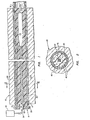
- Fig. 1 is a longitudinal cross-sectional view of a tube-tube sheet interface including the apparatus of the present invention; and
- Fig. 2 is a cross-sectional view taken along the line 2-2 of Fig. 1.
- Referring to Fig. 1 of the drawings, the
reference numeral 10 refers in general to a tube sheet which can form a portion of a heat exchanger having a plurality of heat exchange tubes, one of which is shown by thereference numeral 12. Each tube 12-extends within a corresponding bore formed within thetube sheet 10, with one end of each of the-tubes extending flush with the outer surface of the tube sheet, and the other end extending through the inner surface of the tube sheet. - The outer diameter of the
tube 12 is slightly less than than the inner diameter of the tube sheet bore and the tube may be secured to thetube sheet 10 by anannular weldment 14 which welds the flush end of the tube to the outer surface of the tube sheet. Only a portion of thetube 12 is shown in the interest of clarity, it being understood that the heat exchanger would also include a vessel enclosing the tube sheet and having suitable inlets and outlets for a primary heat exchange fluid and a secondary heat exchange fluid. According to a typical arrangement of this type, thetubes 12 could be U-shaped with both ends of each tube extending through thetube sheet 10 and the heat exchanger would include a partition, or the like. The primary heat exchange fluid would enter thetubes 12 through one end from an area to the left of thetube sheet 10 as viewed in Fig. 1, pass through the tubes in a heat exchange relation with the secondary fluid passing through the vessel to the right of the tube sheet, and exit through the other ends of the tubes. - The
tube 12 is depicted in Fig. 1 prior to it being explosively formed in thetube sheet 10, along with the apparatus of the present invention for effecting the explosive forming. The latter apparatus includes an insert, shown in general by thereference numeral 18, which extends within thetube 12 and consists of a generally tubular force-transmittingmember 20 and a rod-shapedexplosive member 22 extending within the bore of the tubular member. Thetubular member 20 has an outside diameter which is slightly less than the inner diameter of thetube 12, and ashoulder 23 is provided on the end of the tubular member which engages theweldment 14 to precisely locate thetubular member 20, and therefore theentire insert 18, within thetube 12. The length of thetubular member 20 is such that, when positioned within the tube as shown, it extends substantially coextensive with the area of overlap between thetube 12 andtube sheet 10. The end portion of thetubular member 20 extending adjacent the inner surface of thetube sheet 10 is closed, as shown by the reference numeral 20a. - The
explosive member 22 is disposed within the bore of thetubular member 20 intermediate the ends thereof and contains a predetermined number of grains of explosive distributed uniformly along its axis. The bore of thetubular member 20 extending between its closed end portion 20a and the corresponding end portion of theexplosive member 22 is enlarged to form an inner cavity, or chamber, 23. - A
detonator cap 24 is provided externally of thetube sheet 10 and contains a very sensitive primary explosive which detonates readily when set off by a primer, an electrical blast cap, or the like, in a conventional manner. Anenergy transfer cord 26 connects thedetonator cap 24 with theinsert 18, and contains a relatively low number of grains of explosive, surrounded by a protective sheath preferably of a plastic material. The-relative size of the sheath when compared to the explosive potential of the explosives of thecord 26 is such that the sheath will contain the debris and gases resulting from the explosion as will be described in detail later. Further details of theenergy transfer cord 26 are disclosed in copending patent application Serial No. (attorney's docket no. 16,429A - USD 1842A) filed November 15, 1982, and assigned to the same assignee as the present application. - Referring again to Fig. 1, a
counter-bore 32 is formed in thetubular member 20 for receiving abooster 34, with the outer surface of thebooster 34 extending flush with themember 20 and connected to the other end of theenergy transfer cord 26. - Although not shown in the drawings, it is understood that the other end of the
booster 34 is formed with a relatively small cavity-in which an explosive is disposed, with the booster being positioned so that the explosive does not fall outside of the axial location of thetube sheet 10. It is noted that the corresponding end of theexplosive member 22 is slightly spaced from the latter end portion of thebooster 34. - A
fiber material 40 is embedded in the force-transmittingmember 20 and extends longitudinally for the length of the latter member. Thefiber material 40 may be in the form of a continuous filament or may be in the form of a plurality of individual filaments. In either case, the sections or strands of the fiber material extends in a fairly closely spaced relationship as shown in Fig. 2. According to a preferred embodiment, the force-transmittingmember 20 is formed of polyethylene and thefiber material 40. is in the form of fiberglass, graphite or boron. - The
booster 34 is detonated by theenergy transfer cord 26 which, in turn, detonates theexplosive member 22, with the resulting forces being transmitted, via the force-transmitting member, uniformly to thetube 12 to cause a uniform expansion of the tube against the wall portion of thetube sheet 10 forming the corresponding tube-receiving bore. Thebooster 34 is necessary since, in order to properly contain the debris and gases resulting from the detonation of theenergy transfer cord 26, the amount of . explosives contained in the latter cord must be kept below that which is necessary to directly detonate theexplosive member 22. - This arrangement thus provides a distinct advantage over prior art arrangements. For example, the provision of the longitudinally extending fiber material greatly strengthens the force-transmitting member in the longitudinal direction and minimizes the chance of breakup due to longitudinal shock waves.
- Further, the presence of the closed end portion 20a of the tubular member.20 contains the debris and gases resulting from the explosion within the
cavity 23 and thus prevents their escape past the inner surface of thetube sheet 10. - It is understood that several variations may be made in the foregoing without departing from the scope of the invention. For example, the exact materials used, including the number and type of explosives, in the various components can be varied within the scope of the invention.
- A latitude of modification, change and substitution is intended in the-foregoing disclosure and, in some instances, some features of the invention will be employed without a corresponding use of other features. Accordingly, it is appropriate that the appended claims be construed broadly and in a manner consistent with the spirit and scope of the invention therein.
Claims (8)
Applications Claiming Priority (2)
| Application Number | Priority Date | Filing Date | Title |
|---|---|---|---|
| US46824883A | 1983-02-22 | 1983-02-22 | |
| US468248 | 1983-02-22 |
Publications (2)
| Publication Number | Publication Date |
|---|---|
| EP0117153A1 true EP0117153A1 (en) | 1984-08-29 |
| EP0117153B1 EP0117153B1 (en) | 1987-07-08 |
Family
ID=23859039
Family Applications (1)
| Application Number | Title | Priority Date | Filing Date |
|---|---|---|---|
| EP19840301110 Expired EP0117153B1 (en) | 1983-02-22 | 1984-02-21 | Apparatus for forming an explosively expanded tube-tube sheet joint including a fibre reinforced insert having a closed end |
Country Status (3)
| Country | Link |
|---|---|
| EP (1) | EP0117153B1 (en) |
| JP (1) | JPS59183942A (en) |
| DE (1) | DE3464548D1 (en) |
Cited By (2)
| Publication number | Priority date | Publication date | Assignee | Title |
|---|---|---|---|---|
| EP0213699A3 (en) * | 1985-08-26 | 1987-09-30 | Foster Wheeler Development Corporation | Apparatus for forming an explosively expanded tube-tube sheet joint including a barrier tube |
| EP0318142A1 (en) * | 1987-10-13 | 1989-05-31 | The Welding Institute | High rate forming and joining of plastics |
Citations (4)
| Publication number | Priority date | Publication date | Assignee | Title |
|---|---|---|---|---|
| US3175618A (en) * | 1961-11-06 | 1965-03-30 | Pan American Petroleum Corp | Apparatus for placing a liner in a vessel |
| GB1124891A (en) * | 1965-06-28 | 1968-08-21 | Westinghouse Electric Corp | Explosive welding |
| DE1527903B2 (en) * | 1966-04-22 | 1973-05-30 | Wurttembergische Metallwarenfabrik, 7340 Geishngen | METHOD OF PLATING OF HOLLOW BODIES |
| DE1527902B2 (en) * | 1966-04-22 | 1973-08-09 | Württembergische Metallwarenfabrik, 7340 Geislingen | ARRANGEMENT FOR PLATING HOLLOW BODIES |
-
1984
- 1984-01-17 JP JP494384A patent/JPS59183942A/en active Pending
- 1984-02-21 DE DE8484301110T patent/DE3464548D1/en not_active Expired
- 1984-02-21 EP EP19840301110 patent/EP0117153B1/en not_active Expired
Patent Citations (4)
| Publication number | Priority date | Publication date | Assignee | Title |
|---|---|---|---|---|
| US3175618A (en) * | 1961-11-06 | 1965-03-30 | Pan American Petroleum Corp | Apparatus for placing a liner in a vessel |
| GB1124891A (en) * | 1965-06-28 | 1968-08-21 | Westinghouse Electric Corp | Explosive welding |
| DE1527903B2 (en) * | 1966-04-22 | 1973-05-30 | Wurttembergische Metallwarenfabrik, 7340 Geishngen | METHOD OF PLATING OF HOLLOW BODIES |
| DE1527902B2 (en) * | 1966-04-22 | 1973-08-09 | Württembergische Metallwarenfabrik, 7340 Geislingen | ARRANGEMENT FOR PLATING HOLLOW BODIES |
Cited By (2)
| Publication number | Priority date | Publication date | Assignee | Title |
|---|---|---|---|---|
| EP0213699A3 (en) * | 1985-08-26 | 1987-09-30 | Foster Wheeler Development Corporation | Apparatus for forming an explosively expanded tube-tube sheet joint including a barrier tube |
| EP0318142A1 (en) * | 1987-10-13 | 1989-05-31 | The Welding Institute | High rate forming and joining of plastics |
Also Published As
| Publication number | Publication date |
|---|---|
| JPS59183942A (en) | 1984-10-19 |
| DE3464548D1 (en) | 1987-08-13 |
| EP0117153B1 (en) | 1987-07-08 |
Similar Documents
| Publication | Publication Date | Title |
|---|---|---|
| US4494392A (en) | Apparatus for forming an explosively expanded tube-tube sheet joint including a low energy transfer cord and booster | |
| US4649824A (en) | Apparatus for aerospace vehicle separation events using a linear shaped charge | |
| US3409969A (en) | Method of explosively welding tubes to tube plates | |
| US3562887A (en) | Explosive expansion of liner sleeves | |
| US4449280A (en) | Explosive tube expansion | |
| CN108917507A (en) | A kind of variable diameters are radially uniform not to couple continuous charging structure and its loading method | |
| AU2240897A (en) | Detonators having multiple-line input leads | |
| US3411198A (en) | Explosive expansion of tubes into tube sheets | |
| US2891477A (en) | Initiation device desensitized by fluids | |
| US3131467A (en) | Method of explosively bulging a tube by a tape wound about an explosive charge | |
| KR910008234B1 (en) | Metal pipe joints and manufacturing method | |
| FI59983B (en) | EN PAO ICKE-ELEKTRISK INSUFFICIENT BENDING PRESSURE CAPSULE | |
| US3373686A (en) | Explosive actuator | |
| US4685205A (en) | Apparatus for forming an explosively expanded tube-tube sheet joint including a barrier tube | |
| EP0117153B1 (en) | Apparatus for forming an explosively expanded tube-tube sheet joint including a fibre reinforced insert having a closed end | |
| US4333597A (en) | Method of explosively forming bi-metal tubeplate joints | |
| US3446047A (en) | Detonator locating device | |
| US2618221A (en) | Delay blasting device | |
| US4587904A (en) | Debris free plug assembly for heat exchange tubes | |
| Schroeder | Apparatus for forming an explosively expanded tube-tube sheet joint | |
| US5022148A (en) | Method for explosively welding a sleeve into a heat exchanger tube | |
| US5038994A (en) | Apparatus for explosively welding a sleeve into a heat exchanger tube | |
| KR100561361B1 (en) | Explosion bonding method of tube and tube sheet of heat exchanger with small diameter tube hole | |
| US4030419A (en) | Insert for explosively expanding a tube into engagement with a tube sheet | |
| KR950026612A (en) | Plug assembly for sealing leaking pipe of heat exchanger and sealing method using same |
Legal Events
| Date | Code | Title | Description |
|---|---|---|---|
| PUAI | Public reference made under article 153(3) epc to a published international application that has entered the european phase |
Free format text: ORIGINAL CODE: 0009012 |
|
| AK | Designated contracting states |
Designated state(s): DE FR GB SE |
|
| 17P | Request for examination filed |
Effective date: 19850227 |
|
| 17Q | First examination report despatched |
Effective date: 19860415 |
|
| GRAA | (expected) grant |
Free format text: ORIGINAL CODE: 0009210 |
|
| AK | Designated contracting states |
Kind code of ref document: B1 Designated state(s): DE FR GB SE |
|
| REF | Corresponds to: |
Ref document number: 3464548 Country of ref document: DE Date of ref document: 19870813 |
|
| ET | Fr: translation filed | ||
| PLBE | No opposition filed within time limit |
Free format text: ORIGINAL CODE: 0009261 |
|
| STAA | Information on the status of an ep patent application or granted ep patent |
Free format text: STATUS: NO OPPOSITION FILED WITHIN TIME LIMIT |
|
| 26N | No opposition filed | ||
| PGFP | Annual fee paid to national office [announced via postgrant information from national office to epo] |
Ref country code: FR Payment date: 19900210 Year of fee payment: 7 |
|
| PGFP | Annual fee paid to national office [announced via postgrant information from national office to epo] |
Ref country code: SE Payment date: 19900223 Year of fee payment: 7 |
|
| PGFP | Annual fee paid to national office [announced via postgrant information from national office to epo] |
Ref country code: GB Payment date: 19900228 Year of fee payment: 7 |
|
| PGFP | Annual fee paid to national office [announced via postgrant information from national office to epo] |
Ref country code: DE Payment date: 19900330 Year of fee payment: 7 |
|
| PG25 | Lapsed in a contracting state [announced via postgrant information from national office to epo] |
Ref country code: GB Effective date: 19910221 |
|
| PG25 | Lapsed in a contracting state [announced via postgrant information from national office to epo] |
Ref country code: SE Effective date: 19910222 |
|
| GBPC | Gb: european patent ceased through non-payment of renewal fee | ||
| PG25 | Lapsed in a contracting state [announced via postgrant information from national office to epo] |
Ref country code: FR Effective date: 19911031 |
|
| PG25 | Lapsed in a contracting state [announced via postgrant information from national office to epo] |
Ref country code: DE Effective date: 19911101 |
|
| REG | Reference to a national code |
Ref country code: FR Ref legal event code: ST |
|
| EUG | Se: european patent has lapsed |
Ref document number: 84301110.7 Effective date: 19911008 |