EP0116902A2 - Method and arrangement for the adaptive attenuation and group delay equalization at the receiving side - Google Patents
Method and arrangement for the adaptive attenuation and group delay equalization at the receiving side Download PDFInfo
- Publication number
- EP0116902A2 EP0116902A2 EP84101315A EP84101315A EP0116902A2 EP 0116902 A2 EP0116902 A2 EP 0116902A2 EP 84101315 A EP84101315 A EP 84101315A EP 84101315 A EP84101315 A EP 84101315A EP 0116902 A2 EP0116902 A2 EP 0116902A2
- Authority
- EP
- European Patent Office
- Prior art keywords
- frequency
- microprocessor
- arrangement
- group delay
- frequency distribution
- Prior art date
- Legal status (The legal status is an assumption and is not a legal conclusion. Google has not performed a legal analysis and makes no representation as to the accuracy of the status listed.)
- Granted
Links
Images
Classifications
-
- H—ELECTRICITY
- H04—ELECTRIC COMMUNICATION TECHNIQUE
- H04L—TRANSMISSION OF DIGITAL INFORMATION, e.g. TELEGRAPHIC COMMUNICATION
- H04L25/00—Baseband systems
- H04L25/02—Details ; arrangements for supplying electrical power along data transmission lines
- H04L25/03—Shaping networks in transmitter or receiver, e.g. adaptive shaping networks
- H04L25/03006—Arrangements for removing intersymbol interference
- H04L25/03012—Arrangements for removing intersymbol interference operating in the time domain
- H04L25/03019—Arrangements for removing intersymbol interference operating in the time domain adaptive, i.e. capable of adjustment during data reception
-
- H—ELECTRICITY
- H04—ELECTRIC COMMUNICATION TECHNIQUE
- H04L—TRANSMISSION OF DIGITAL INFORMATION, e.g. TELEGRAPHIC COMMUNICATION
- H04L25/00—Baseband systems
- H04L25/02—Details ; arrangements for supplying electrical power along data transmission lines
- H04L25/03—Shaping networks in transmitter or receiver, e.g. adaptive shaping networks
Definitions
- QAM quadrature amplitude modulation
- PSK phase shift keying
- the two-way or multipath fading on radio transmission links leads to distortion of the RF signal.
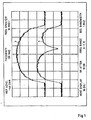
- 1 shows a transmitted signal spectrum with and without fading.
- the frequency-selective incision (FIG . 1b) causes a deterioration in the transmission quality, which has the effect of an increase in the bit error rate.
- This distortion of the transmission channel can in principle be compensated for by equalizers.
- the equalizer In the event of fading phenomena in the microwave range, which can occur and disappear within seconds, the equalizer must be adaptive.
- Adaptive equalizers are already known for the equalization of received data signals in the time domain (Millermann, K., "Some methods for adaptive adjustment of equalizers for fast data processing" NTZ, 24 (1971), pages 18 to 24).
- the coefficients of a transversal filter are corrected by means of control voltages which are determined from the mean square deviation of the received time function from its target value. Since the distortion of the transmission channel, one can also realize the equalizer in the frequency domain by the D ämpfungs- and group delay distortion of the channel are eliminated by an adjustable equalizer or decreased.
- Such a method for baseband signals is given, for example, by W. Schmidt in his work: "An automatic adaptive equalizer for digital transmission” Proc. IEE E Symp. C i rc. and systems, NY 1978, pages 436 to 440.
- the invention was based on the object of creating an adaptive equalization for dynamic attenuation and group delay distortions in the intermediate frequency range of 140 MHz.
- This object is achieved in the method according to the invention in that first the frequency distribution of the discrete amplitude levels in the demodulated signal is measured, compared in the control unit of a microprocessor with the corresponding expected values and the difference for controlling the coefficient setting elements; one in the high-frequency, preferably in the intermediate-frequency, branch of the receiver arranged Lee-Wiener equalizer is used.
- the frequency distribution is determined by a probability decoder connected to the demodulator, which determines the deviation from the mean value of the amplitude levels by low-pass filtering by integration over several symbol durations, and uses this to generate the digital control signals for the microprocessor via an analog-digital converter.
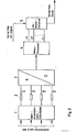
- Fig. 2 shows the block diagram of the arrangement according to the invention.
- the microprocessor 4 compares the incoming actual probability the amplitude distribution with the theoretically expected or transmitted probability.
- the microprocessor 4 calculates the analog control variables for the coefficients of a Lee-Wiener equalizer 5, which is preferably designed for the intermediate frequency range and consists of a cascade connection of all-pass filters of the first order, as used, for example, by YW Lee in his work "Synthesis of Eletrical Networks by means of the Fourier-Transforms of Laguerre's Funtions” J ourn. Math. Phys. 11 (1932), pages 83 to 113.
- the filter coefficients that can be changed by the microprocessor 4 adjust the transfer function of the Lee-Wiener equalizer 5 so that the attenuation and group delay distortions of the received signal are compensated for at its output.
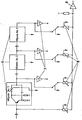
- FIG. 3 shows the basic circuit diagram of the microprocessor-controlled adaptive Lee-Wiener equalizer.
- the three-stage structure chosen here with the three all-passports 6 shows A total of ten control connections marked by arrows for the microprocessor, of which, however, depending on the application, a part can be replaced by permanently adjustable controllers or switches.
- inverters 7 With the help of inverters 7, the sign of the filter coefficients can be reversed if necessary.
- the four potentiometers 8 shown in FIG. 3 below are replaced by field-effect transistors when the Lee-Wiener equalizer is connected to the microprocessor. In a realized example, these were the manipulated variables addressed by the microprocessor.
- the emitter follower 9 on the output side serves for decoupling.
Landscapes
- Engineering & Computer Science (AREA)
- Power Engineering (AREA)
- Computer Networks & Wireless Communication (AREA)
- Signal Processing (AREA)
- Cable Transmission Systems, Equalization Of Radio And Reduction Of Echo (AREA)
Abstract
Die Erfindung erzielt eine empfangsseitige adaptive Dämpfungs- und Gruppenlaufzeitsentzerrung auf schwundbehafteten digitalen Funkübertragungswegen mit Quadratur-Amplituden-Modulation (QAM) bzw. Phasenumtastung (PSK = Phase Shift Keying). Dazu wird zunächst die Häufigkeitsverteilung der diskreten Amplitudenstufen im demodulierten Signal gemessen, in der Steuereinheit eines Mikroprozessors (4 in Fig. 2) mit den entsprechenden Erwartungswerten verglichen und die Differenz zum Steuern der Koeffizienteneinstellglieder eines im hochfrequenten, vorzugsweise im zwischenfrequenten, Zweig des Empfängers angeordneten Lee-Wiener-Entzerrers (5) verwendet. Die Häufigkeitsverteilung wird durch einen an den Demodulator angeschalteten Wahrscheinlichkeitsentscheider (1) festgestellt, der durch Integration über mehrere Symboldauern die Abweichung vom Mittelwert der Amplitudenstufen durch Tiefpaßfilterung (2) ermittelt und daraus über einen Analog-Digital-Wandler (3) die digitalen Steuersignale für den Mikroprozessor (4) erzeugt (Fig. 2).
Description
Verfahren und Anordnung zur empfangsseitigen adaptiven Dämpfungs- und GruppenlaufzeitsentzerrungMethod and arrangement for adaptive attenuation and group delay equalization at the receiving end
Die Erfindung betrifft ein Verfahren und eine Anordnung zur empfangsseitigen adaptiven Dämpfungs- und Gruppenlaufzeitsentzerrung auf schwundbehafteten digitalen Funkübertragungswegen mit Quadratur-Amplituden-Modulation (QAM) bzw. Phasenumtastung (PSK = Phase Shift Keying). Der Zwei- oder Mehrwegeschwund auf Funkübertragungsstrecken führt zu Verzerrungen des RF-Signals. Fig. 1 zeigt ein übertragenes Signalspektrum mit und ohne Schwund. Der frequenzselektive Einschnitt (Fig. 1b) verursacht eine Verschlechterung.der Übertragungsqualität, die sich als Anstieg der Bitfehlerquote auswirkt. Diese Verzerrung des Übertragungskanals kann grundsätzlich von Entzerrern ausgeglichen werden. Im Falle von Schwunderscheinungen im Mikrowellenbereich, die innerhalb von Sekunden auftreten und wieder verschwinden können, muß der Entzerrer adaptiv sein.The invention relates to a method and an arrangement for receiving-side adaptive damping and group delay equalization on fading digital radio transmission paths with quadrature amplitude modulation (QAM) or phase shift keying (PSK = phase shift keying). The two-way or multipath fading on radio transmission links leads to distortion of the RF signal. 1 shows a transmitted signal spectrum with and without fading. The frequency-selective incision (FIG . 1b) causes a deterioration in the transmission quality, which has the effect of an increase in the bit error rate. This distortion of the transmission channel can in principle be compensated for by equalizers. In the event of fading phenomena in the microwave range, which can occur and disappear within seconds, the equalizer must be adaptive.
Für die Entzerrung empfangener Datensignale im Zeitbereich sind bereits adaptive Entzerrer bekannt (Möhrmann, K., "Einige Verfahren zur adaptiven Einstellung von Entzerrern für die schnelle Datenverarbeitung" NTZ, 24 (1971), Seiten.18 bis 24). Bei dieser Art von Entzerrern werden die Koeffizienten eines Transversalfilters mittels Regelspannungen korrigiert, die aus der mittleren quadratischen Abweichung der empfangenen Zeitfunktion von ihrem Sollwert bestimmt werden. Da die Verzerrungen im Übertragungskanal entstehen, kann man den Entzerrer auch im Frequenzbereich realisieren, indem die Dämpfungs- und Gruppenlaufzeitsverzerrungen des Kanals durch einen einstellbaren Entzerrer beseitigt oder verringert werden. Ein solches Verfahren für Basisbandsignale ist beispielsweise angegeben von W. Schmidt in seiner Arbeit: "An automatic adaptive Equalizer for digital Transmission" Proc. IEEE Symp. Circ. and systems, N.Y. 1978, Seiten 436 bis 440.Adaptive equalizers are already known for the equalization of received data signals in the time domain (Möhrmann, K., "Some methods for adaptive adjustment of equalizers for fast data processing" NTZ, 24 (1971), pages 18 to 24). In this type of equalizer, the coefficients of a transversal filter are corrected by means of control voltages which are determined from the mean square deviation of the received time function from its target value. Since the distortion of the transmission channel, one can also realize the equalizer in the frequency domain by the D ämpfungs- and group delay distortion of the channel are eliminated by an adjustable equalizer or decreased. Such a method for baseband signals is given, for example, by W. Schmidt in his work: "An automatic adaptive equalizer for digital transmission" Proc. IEE E Symp. C i rc. and systems, NY 1978, pages 436 to 440.
Die zitierten Verfahren sind bei niedrigen Basisbandfrequenzen bzw. niedrigen Bitraten realisiert worden und gehen davon aus, daß die Verzerrungen zeitinvariant sind. Beim Auftreten von dynamischen, frequenzselektiven Schwunderscheinungen (z..B. im Richtfunk) hilft man sich durch Verwendung von Diversity-Verfahren.The methods cited have been implemented at low baseband frequencies or low bit rates and assume that the distortions are time-invariant. If dynamic, frequency-selective fading phenomena (e.g. in radio relay) occur, you can help yourself by using diversity methods.
Der Erfindung lag nun die Aufgabe zugrunde, im Zwischenfrequenzbereich von 140 MHz eine adaptive Entzerrung für dynamische Dämgfungs- und Gruppenlaufzeitverzerrungen zu schaffen.The invention was based on the object of creating an adaptive equalization for dynamic attenuation and group delay distortions in the intermediate frequency range of 140 MHz.
Diese Aufgabe wird bei dem Verfahren nach der Erfindung dadurch gelöst, daß zunächst die Häufigkeitsverteilung der diskreten Amplitudenstufen im demodulierten Signal gemessen, in der Steuereinheit eines Mikroprozessors mit den entsprechenden Erwartungswerten verglichen und die Differenz zum Steuern der Koeffizienteneinstellglieder; eines im hochfrequenten, vorzugsweise im zwischenfrequenten, Zweig des Empfängers angeordneten Lee-Wiener-Entzerrers verwendet wird.This object is achieved in the method according to the invention in that first the frequency distribution of the discrete amplitude levels in the demodulated signal is measured, compared in the control unit of a microprocessor with the corresponding expected values and the difference for controlling the coefficient setting elements; one in the high-frequency, preferably in the intermediate-frequency, branch of the receiver arranged Lee-Wiener equalizer is used.
Die Häufigkeitsverteilung wird bei einer bevorzugten Weiterbildung der Erfindung durch einen an den Demodulator angeschalteten Wahrscheinlichkeitsentscheider festgestellt, der durch Integration über mehrere Symboldauern die Abweichung vom Mittelwert der Amplitudenstufen durch Tiefpaßfilterung ermittelt und daraus über einen Analog-Digital-Wandler die digitalen Steuersignale für den Mikroprozessor erzeugt.In a preferred development of the invention, the frequency distribution is determined by a probability decoder connected to the demodulator, which determines the deviation from the mean value of the amplitude levels by low-pass filtering by integration over several symbol durations, and uses this to generate the digital control signals for the microprocessor via an analog-digital converter.
Im folgenden wird die Erfindung anhand von Fig. 1 bis 3 näher erläutert. Es zeigen
- Fig. 1 die bereits erwähnten Signalspektren mit und ohne Schwund
- Fig. 2 ein Blockschaltbild der Schaltungsanordnung nach der Erfindung
- Fig. 3 ein Prinzipschaltbild des in einem Ausführungsbeispiel verwendeten Lee-Wiener-Entzerrers.
- Fig. 1, the signal spectra already mentioned with and without fading
- Fig. 2 is a block diagram of the circuit arrangement according to the invention
- Fig. 3 is a schematic diagram of the Lee-Wiener equalizer used in one embodiment.
Fig. 2 zeigt das Blockschaltbild der Anordnung nach der Erfindung. Eine an den Regeneratorausgängen, also hinter dem QAM-Demodulator liegende Schaltung 1 entscheidet über die Wahrscheinlichkeit der auftretenden Amplitudenstufen und erzeugt über Tiefpässe 2 und einen Analog-Digital-Wandler 3 ein digitales Steuersignal für einen Mikroprozessor 4. Der Mikroprozessor 4 vergleicht die ankommende tatsächliche Wahrscheinlichkeit der Amplitudenverteilung mit der theoretisch zu erwartenden bzw. gesendeten Wahrscheinlichkeit. Aus der Abweichung von Soll- und Ist-Wert berechnet der Mikroprozessor 4 die analogen Regelgrößen für die Koeffizienten eines vorzugsweise für den Zwischenfrequenzbereich ausgelegten Lee-Wiener-Entzerrers 5, der aus einer Kaskadenschaltung von Allpässen erster Ordnung besteht, wie sie beispielsweise von Y.W. Lee in seiner Arbeit "Synthesis of Eletrical Networks by means of the Fourier-Transforms of Laguerre's Funtions"Journ. Math. Phys. 11 (1932), Seiten 83 bis 113, beschrieben wurden.Fig. 2 shows the block diagram of the arrangement according to the invention. A
Die n vom Mikroprozessor 4 aus veränderbaren Filterkoeffizienten verstellen die Übertragungsfunktion des Lee-Wiener-Entzerrers 5 so, daß an dessen Ausgang die Dämpfungs- und Gruppenlaufzeitverzerrungen des empfangenen Signals ausgeglichen sind.The filter coefficients that can be changed by the
Fig. 3 zeigt das Prinzipschaltbild des mikroprozessorgesteuerten adaptiven Lee-Wiener-Entzerrers. Der hier gewählte dreistufige Aufbau mit den drei Allpässen 6 zeigt insgesamt zehn durch Pfeile gekennzeichnete Steueranschlüsse für den Mikroprozessor, von denen aber je nach Anwendungsfall ein Teil durch festeinstellbare Regler bzw. Schalter ersetzt werden kann. Mit Hilfe von Invertern 7 läßt sich das Vorzeichen der Filterkoeffizienten bedarfsweise umkehren.3 shows the basic circuit diagram of the microprocessor-controlled adaptive Lee-Wiener equalizer. The three-stage structure chosen here with the three all-
Die vier in Fig. 3 unten dargestellten Potentiometer 8 werden bei Anschluß des Lee-Wiener-Entzerrers an den Mikroprozessor durch Feldeffekttransistoren ersetzt. In einem realisierten Beispiel waren dies die vom Mikroprozessor aus angesprochenen Stellgrößen. Der ausgangsseitige Emitterfolger 9 dient zur Entkopplung.The four
Claims (2)
Applications Claiming Priority (2)
| Application Number | Priority Date | Filing Date | Title |
|---|---|---|---|
| DE3305797 | 1983-02-19 | ||
| DE19833305797 DE3305797A1 (en) | 1983-02-19 | 1983-02-19 | METHOD AND ARRANGEMENT FOR RECEIVING ADAPTIVE DAMPING AND GROUP RUNNING EQUALIZATION |
Publications (3)
| Publication Number | Publication Date |
|---|---|
| EP0116902A2 true EP0116902A2 (en) | 1984-08-29 |
| EP0116902A3 EP0116902A3 (en) | 1987-01-07 |
| EP0116902B1 EP0116902B1 (en) | 1989-09-27 |
Family
ID=6191288
Family Applications (1)
| Application Number | Title | Priority Date | Filing Date |
|---|---|---|---|
| EP84101315A Expired EP0116902B1 (en) | 1983-02-19 | 1984-02-09 | Method and arrangement for the adaptive attenuation and group delay equalization at the receiving side |
Country Status (2)
| Country | Link |
|---|---|
| EP (1) | EP0116902B1 (en) |
| DE (2) | DE3305797A1 (en) |
Cited By (2)
| Publication number | Priority date | Publication date | Assignee | Title |
|---|---|---|---|---|
| GB2201870A (en) * | 1987-03-04 | 1988-09-07 | Nat Semiconductor Corp | Convolution data recovery circuit |
| FR2639497A1 (en) * | 1988-11-21 | 1990-05-25 | France Etat | DEMODULATOR FOR DIGITAL TRANSMISSION COMPRISING AN AUTOMATIC DEFECT CORRECTION DEVICE |
Families Citing this family (1)
| Publication number | Priority date | Publication date | Assignee | Title |
|---|---|---|---|---|
| DE19543622C2 (en) * | 1995-11-23 | 1999-12-30 | Deutsche Telekom Ag | Method and device for the bidirectional transmission of high-rate digital signals |
Family Cites Families (1)
| Publication number | Priority date | Publication date | Assignee | Title |
|---|---|---|---|---|
| US3071739A (en) * | 1961-04-21 | 1963-01-01 | Bell Telephone Labor Inc | Digital phase equalizer, automatically operative, in accordance with time-inverted impulse response of the transmission circuit |
-
1983
- 1983-02-19 DE DE19833305797 patent/DE3305797A1/en not_active Withdrawn
-
1984
- 1984-02-09 EP EP84101315A patent/EP0116902B1/en not_active Expired
- 1984-02-09 DE DE8484101315T patent/DE3479951D1/en not_active Expired
Cited By (5)
| Publication number | Priority date | Publication date | Assignee | Title |
|---|---|---|---|---|
| GB2201870A (en) * | 1987-03-04 | 1988-09-07 | Nat Semiconductor Corp | Convolution data recovery circuit |
| GB2201870B (en) * | 1987-03-04 | 1991-07-03 | Nat Semiconductor Corp | Convolution data recovery circuit |
| FR2639497A1 (en) * | 1988-11-21 | 1990-05-25 | France Etat | DEMODULATOR FOR DIGITAL TRANSMISSION COMPRISING AN AUTOMATIC DEFECT CORRECTION DEVICE |
| EP0375478A1 (en) * | 1988-11-21 | 1990-06-27 | ETAT FRANCAIS représenté par le Ministre des Postes, Télécommunications et de l'Espace | Demodulator for digital transmission with a device for automatically correcting errors |
| US4959619A (en) * | 1988-11-21 | 1990-09-25 | ETAT FRANCAIS, repreesente par la Ministre des Postes, Telecommunications et de 1'Espace (Centre National d'Etudes des Telecommunications) | Digital transmission demodulator including an automatic fault corrector |
Also Published As
| Publication number | Publication date |
|---|---|
| EP0116902B1 (en) | 1989-09-27 |
| EP0116902A3 (en) | 1987-01-07 |
| DE3305797A1 (en) | 1984-08-23 |
| DE3479951D1 (en) | 1989-11-02 |
Similar Documents
| Publication | Publication Date | Title |
|---|---|---|
| DE60124870T2 (en) | Method and apparatus for implementing a training phase of adaptive channel equalization for a digital communication path | |
| EP1217760A1 (en) | Apparatus and method for data communication over power line network | |
| DE60033623T2 (en) | Equalization for a multi-channel receiving node | |
| DE1934456A1 (en) | Adaptive equalizer | |
| DE60131336T2 (en) | QAM receiver with gain control, correction of DC offsets and passband equalization | |
| EP0116902B1 (en) | Method and arrangement for the adaptive attenuation and group delay equalization at the receiving side | |
| DE3146483C2 (en) | ||
| EP1383237A2 (en) | Adaptive equalizer with integrated adjustment of the output level | |
| EP0080020B1 (en) | Method of determining the optimum sampling instants of a qpsk or qam reception signal | |
| DE69527079T2 (en) | ADAPTIVE EQUALIZER | |
| DE60300886T2 (en) | MODULAR BUILT-UP DEVICE FOR THE DIVERSITY RECEPTION OF A MODULATED SIGNAL | |
| EP0537587A2 (en) | Method for the determination of the coefficients of an equalizer for QAM transmission | |
| DE19944558A1 (en) | Method for sending radio signals and transmitter for sending radio signals | |
| DE60204903T2 (en) | BETWEEN SYMBOL FAULT EXTINGUISHERS | |
| DE1135967B (en) | Arrangement for balancing unbalanced listener frequency signals | |
| DE3730399A1 (en) | Method and device for transmitting a digital signal | |
| DE69106030T2 (en) | Control an adaptive equalizer. | |
| DE2217355A1 (en) | Changeable equalizer for a broadband cable system | |
| EP0900456A1 (en) | Process and device for reception with directional resolution | |
| DE3508045C2 (en) | Adaptive equalizer for orthogonally modulated digital signals | |
| EP0398169A1 (en) | Car radio with a digital equalizing network | |
| EP0098588B1 (en) | Adaptive equalizer for the equalization of multilevel signals | |
| DE3132012A1 (en) | Arrangement for equalising amplitude and phase distortions on transmission paths for analog signals | |
| DE602844C (en) | Procedure for eliminating interference in electrical communication by means of character transmission | |
| DE1791202B2 (en) | ADJUSTABLE ELECTRIC EQUALIZATION CIRCUIT |
Legal Events
| Date | Code | Title | Description |
|---|---|---|---|
| PUAI | Public reference made under article 153(3) epc to a published international application that has entered the european phase |
Free format text: ORIGINAL CODE: 0009012 |
|
| AK | Designated contracting states |
Designated state(s): DE FR SE |
|
| PUAL | Search report despatched |
Free format text: ORIGINAL CODE: 0009013 |
|
| AK | Designated contracting states |
Kind code of ref document: A3 Designated state(s): DE FR SE |
|
| 17P | Request for examination filed |
Effective date: 19861128 |
|
| 17Q | First examination report despatched |
Effective date: 19881006 |
|
| GRAA | (expected) grant |
Free format text: ORIGINAL CODE: 0009210 |
|
| AK | Designated contracting states |
Kind code of ref document: B1 Designated state(s): DE FR SE |
|
| REF | Corresponds to: |
Ref document number: 3479951 Country of ref document: DE Date of ref document: 19891102 |
|
| ET | Fr: translation filed | ||
| PLBE | No opposition filed within time limit |
Free format text: ORIGINAL CODE: 0009261 |
|
| STAA | Information on the status of an ep patent application or granted ep patent |
Free format text: STATUS: NO OPPOSITION FILED WITHIN TIME LIMIT |
|
| 26N | No opposition filed | ||
| REG | Reference to a national code |
Ref country code: FR Ref legal event code: DL |
|
| PGFP | Annual fee paid to national office [announced via postgrant information from national office to epo] |
Ref country code: FR Payment date: 19920214 Year of fee payment: 9 |
|
| PGFP | Annual fee paid to national office [announced via postgrant information from national office to epo] |
Ref country code: SE Payment date: 19920226 Year of fee payment: 9 |
|
| PG25 | Lapsed in a contracting state [announced via postgrant information from national office to epo] |
Ref country code: SE Effective date: 19930210 |
|
| PG25 | Lapsed in a contracting state [announced via postgrant information from national office to epo] |
Ref country code: FR Effective date: 19931029 |
|
| REG | Reference to a national code |
Ref country code: FR Ref legal event code: ST |
|
| EUG | Se: european patent has lapsed |
Ref document number: 84101315.4 Effective date: 19930912 |
|
| PGFP | Annual fee paid to national office [announced via postgrant information from national office to epo] |
Ref country code: DE Payment date: 19970418 Year of fee payment: 15 |
|
| PG25 | Lapsed in a contracting state [announced via postgrant information from national office to epo] |
Ref country code: DE Free format text: LAPSE BECAUSE OF NON-PAYMENT OF DUE FEES Effective date: 19991201 |