EP0116748A1 - On-load tap changer - Google Patents
On-load tap changer Download PDFInfo
- Publication number
- EP0116748A1 EP0116748A1 EP83306465A EP83306465A EP0116748A1 EP 0116748 A1 EP0116748 A1 EP 0116748A1 EP 83306465 A EP83306465 A EP 83306465A EP 83306465 A EP83306465 A EP 83306465A EP 0116748 A1 EP0116748 A1 EP 0116748A1
- Authority
- EP
- European Patent Office
- Prior art keywords
- switch
- current
- tap
- main
- switches
- Prior art date
- Legal status (The legal status is an assumption and is not a legal conclusion. Google has not performed a legal analysis and makes no representation as to the accuracy of the status listed.)
- Withdrawn
Links
Images

Classifications
-
- H—ELECTRICITY
- H01—ELECTRIC ELEMENTS
- H01F—MAGNETS; INDUCTANCES; TRANSFORMERS; SELECTION OF MATERIALS FOR THEIR MAGNETIC PROPERTIES
- H01F29/00—Variable transformers or inductances not covered by group H01F21/00
- H01F29/02—Variable transformers or inductances not covered by group H01F21/00 with tappings on coil or winding; with provision for rearrangement or interconnection of windings
- H01F29/04—Variable transformers or inductances not covered by group H01F21/00 with tappings on coil or winding; with provision for rearrangement or interconnection of windings having provision for tap-changing without interrupting the load current
Definitions
- This invention relates to an on-load tap changer, and more particularly to an on-load tap changer which employs resistors as current-limiting bridge elements.
- FIG. 1 of the accompanying drawings A known on-load tap changer of this type is shown in Figure 1 of the accompanying drawings.
- the tap selecting arms 1 and 2 of a tap selector for respectively selecting the odd-numbered side tap and even-numbered side tap of a transformer adjusting winding T are connected to the winding.
- An odd-numbered side input terminal 3 and even-numbered side input terminal 4 are respectively connected to the tap selecting arms 1 and 2.
- An odd-numbered side main switch A and even-numbered side main switch B are respectively connected to the input terminals 3 and 4.
- the respective main switches are constructed of stationary contacts 5, 6, and movable contacts 7. 8 adapted to come into and out of contact with the stationary contacts 5, 6.
- Current-limiting resistors Rl, R2 are connected in parallel with the respective main switches A, B, and electric paths are changed so that load currents may flow through the current-limiting resistors Rl, R2 when the main switches are opened.
- an odd-numbered side auxiliary switch C and even-numbered side auxiliary switch D are connected to a common output terminal 13.
- the respective auxiliary switches are constructed of stationary contacts 9, 10 connected to the corresponding movable contacts 7, 8, and movable contacts 11, 12 adapted to come into and out of contact with the corresponding stationary contacts 9, 10.
- Figure 1 illustrates the state in which the movable contacts 7 and 11 are respectively engaged with stationary contacts 5 and 9. so that the load current is conducted by the odd-numbered side tap to pass along the path from the transformer adjusting winding T.
- the main switches A and B are located on the input terminal side and have the current-limiting resistors connected in parallel therewith, the inter-tap voltage of the transformer winding is applied across the main switch at all times. This leads to the disadvantage that the switching drive mechanism of the main switch must be sufficiently insulated.
- An object of this invention is to eliminate the disadvantage of the prior art as stated above, without losing the advantages thereof.
- main switches on an odd-numbered side and an even-numbered side, and current-limiting resistors connected in parallel therewith, are disposed on the output terminal side, while the auxiliary switches are disposed on the input terminal or tap selector side.
- the stationary contacts of the main switches and auxiliary switches are arrayed on the input terminal side, with the movable contact thereof being arrayed on the output terminal side: and the tap selectors and the stationary contacts of the auxiliary switches, the movable contacts of the auxiliary switches and the stationary contacts of the main switches, and the movable contacts of the main switches and an output terminal, are respectively connected.
- an inter-tap voltage acts on the movable contact of the auxiliary switch only midway of the tap change.
- the invention accordingly provides an on-load tap changer which is highly reliable in insulation and in which no inter-tap voltage acts on the movable contacts of the main and auxiliary switches no matter which of the odd-numbered side or the even-numbered side is closed to execute a steady operation.
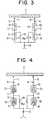
- Figure 3 illustrates the state of steady operation with an odd-numbered tap, in which the movable contact 7 of the odd-numbered side main switch A and the movable contact 11 of the odd-numbered side auxiliary switch C are respectively engaged with the stationary contact 5 of the main switch A and the stationary contact 9 of the auxiliary switch C, respectively, so that a load current flows from the transformer adjusting winding T through the current path
- the movable contacts 7, 8, 11 are at the potential of the output terminal, and also the movable contact 12 of the "even" auxiliary switch is at the output potential through the current-limiting resistor R2.
- the device of the invention keeps intact the advantage of the prior-art device that even when the abnormal voltage tends to form a short-circuit or there is no inter-tap short-circuit, owing to the insertion of the current-limiting resistor Rl or R2 Furthermore, the movable contacts of the main and auxiliary switches on the side which is closed in the steady operation state and the movable contact of the main switch on the opened side lie, of course, at the output terminal potential, and also the movable contact of the auxiliary switch on the opened side attains the output terminal potential through the current-limiting resistor, so that all of the four movable contacts 7, 8, 11, 12 can be held at the output terminal potential.
- the movable contacts are driven by switching drive mechanisms which are set at the output terminal potential, the movable contacts of the two auxiliary switches located on the input terminal sides are driven through insulators, but unlike the prior-art device, the insulators have voltages applied thereto only during the transient period of the tap change and have no voltage applied thereto during the steady operation. This adds the advantage that the reliability of insulation is sharply enhanced.
- FIG 4 shows another embodiment, in which vacuum switches A1, Bl and Cl, Dl are respectively employed as the main switches A, B and auxiliary switches C, D in Figure 3, and which achieves similar effects.
- this invention has the effect of remarkably enhancing the reliability of tap change by a simple construction.
Landscapes
- Engineering & Computer Science (AREA)
- Power Engineering (AREA)
- Protection Of Transformers (AREA)
- Control Of Electrical Variables (AREA)
Abstract
An on-load tap changer wherein diverter switch circuits each of which is a series connection of a main switch A, B and an auxiliary switch C, D are connected between an output terminal (13) and a plurality of tap selecting arms (1, 2) and wherein resistors R1, R2 are employed as current-limiting bridge elements. The main switch has a movable contact (7, 8) connected to the output terminal, the auxiliary switch has a movable contact (11, 12) connected to a stationary contact (5, 6) of the main switch and a stationary contact (9, 10) connected to the odd-input terminal (3, 4) and the current-limiting resistors are respectively connected in parallel with the main switches. The switches are preferably vacuum switches.
Description
- This invention relates to an on-load tap changer, and more particularly to an on-load tap changer which employs resistors as current-limiting bridge elements.
- A known on-load tap changer of this type is shown in Figure 1 of the accompanying drawings. The
tap selecting arms 1 and 2 of a tap selector for respectively selecting the odd-numbered side tap and even-numbered side tap of a transformer adjusting winding T are connected to the winding. An odd-numberedside input terminal 3 and even-numberedside input terminal 4 are respectively connected to thetap selecting arms 1 and 2. An odd-numbered side main switch A and even-numbered side main switch B are respectively connected to theinput terminals stationary contacts stationary contacts common output terminal 13. The respective auxiliary switches are constructed ofstationary contacts movable contacts stationary contacts - Figure 1 illustrates the state in which the
movable contacts 7 and 11 are respectively engaged withstationary contacts from the transformer adjusting winding T.
- The principle of a tap change operation in the case of changing from this state to an even-numbered tap will be described with reference to the operating sequence illustrated in Figure 2. Symbols in this figure correspond tc those in Figure 1.
- i First, when the movable contact 7 of the main switch A is disengaged from the
stationary contact 5, the load current is supplied via the current path
- Secondly, when the
movable contact 12 of the even-numbered side auxiliary switch D is engaged with thestationary contact 10, the load current is divided in two and is supplied via the current pathand the current path Further, an inter-tap circulating current flows through the current path

- Subsequently, when the
movable contact 11 of the odd-numbered side auxiliary switch C is disengaged from thestationary contact 9, the load current is supplied by the current path
- Next, when the movable contact 8 of the even-numbered main switch B is engaged with the
stationary contact 6, the load current is supplied by the current pathThe change from the odd-numbered tap to the even-numbered tap is now complete.
- To change to an odd-numbered tap again, the reverse operation to the above change operation is carried out, and the current conducting sequence is exactly the reverse relationship to the case of the above change. (This is called the "electrical reversible relationship".)
- As described above, with the prior-art device shown in Figure 1, even if the main switch A or B fails to interrupt the current in the course of the tap change, the auxiliary switch C or D which is connected in series with the corresponding main switch and which is opened later than the corresponding main switch effects backup interruption, so that the reliability of the tap change is enhanced. In addition, if an abnormal voltage appears on the transformer adjusting winding T into the side which is open-circuited by the main switch A or B and the auxiliary switch C or D, dielectric breakdown takes place between the
movable contact stationary contact  there is no inter-tap short-circuit of the transformer adjusting winding T, owing to the insertion of the current-limiting resistor Rl or R2. Meanwhile, since the mechanism is so constructed as to drive the movable contact of each switch without interposing any insulator, or the switching drive mechanism is held at the potential of the output terminal. That is, the switching drive mechanism is held at the output terminal potential in order to simplify the construction of the device by dispensing with an insulator. Since, in this case, the main switches A and B are located on the input terminal side and have the current-limiting resistors connected in parallel therewith, the inter-tap voltage of the transformer winding is applied across the main switch at all times. This leads to the disadvantage that the switching drive mechanism of the main switch must be sufficiently insulated.
- An object of this invention is to eliminate the disadvantage of the prior art as stated above, without losing the advantages thereof. According to the invention, main switches on an odd-numbered side and an even-numbered side, and current-limiting resistors connected in parallel therewith, are disposed on the output terminal side, while the auxiliary switches are disposed on the input terminal or tap selector side. The stationary contacts of the main switches and auxiliary switches are arrayed on the input terminal side, with the movable contact thereof being arrayed on the output terminal side: and the tap selectors and the stationary contacts of the auxiliary switches, the movable contacts of the auxiliary switches and the stationary contacts of the main switches, and the movable contacts of the main switches and an output terminal, are respectively connected. Thus, an inter-tap voltage acts on the movable contact of the auxiliary switch only midway of the tap change. The invention accordingly provides an on-load tap changer which is highly reliable in insulation and in which no inter-tap voltage acts on the movable contacts of the main and auxiliary switches no matter which of the odd-numbered side or the even-numbered side is closed to execute a steady operation.
- Embodiments of the invention are shown in Figs. 3 and 4 of the accompanying drawings, in which:
- Figure 2 is an operating sequence diagram of a device according to the present invention:
- Figure 3 is a connection diagram of an embodiment of this invention: and
- Figure 4 is a connection diagram of another embodiment of this invention.
- In the drawings, the same symbols indicate the same of corresponding parts.
- In Figure 3, the same parts as in Figure 1 are assigned the same symbols, and the parts will not be explained again. In the illustrated embodiment, odd-and even-numbered side main switches A, B and current-limiting resistors Rl, R2 connected in parallel therewith are connected to the common output terminal 31, while odd-numbered and even-numbered side auxiliary switches C, D are connected to the
input terminals stationary contacts input terminals output terminal 13. Tap selectingarms 1, 2 are connected to thestationary contacts movable contacts stationary contacts output terminal 13. The operations and effects of the device will be described below. - Figure 3 illustrates the state of steady operation with an odd-numbered tap, in which the movable contact 7 of the odd-numbered side main switch A and the
movable contact 11 of the odd-numbered side auxiliary switch C are respectively engaged with thestationary contact 5 of the main switch A and thestationary contact 9 of the auxiliary switch C, respectively, so that a load current flows from the transformer adjusting winding T through the current pathAt this time, the
movable contacts 7, 8, 11 are at the potential of the output terminal, and also themovable contact 12 of the "even" auxiliary switch is at the output potential through the current-limiting resistor R2. - The operating principle of changing from this state to the even-numbered tap will be described with reference to the operating sequence of Figure 2. First, when the movable contact 7 of the odd-numbered side main switch A is disengaged from its
stationary contact 5, the load current is supplied via the current pathAt this time, a voltage drop component based on the load current flowing through the current-limiting resistor Rl, namely, an inter-tap voltage develops across the
movable contact 11. - Subsequently, when the
movable contact 12 of the even-numbered auxiliary switch D is thrown on itsstationary contact 10, the load current is divided in two and is supplied by the current pathsand Further, a circulating current flows through the current path

- At this time, voltage corresponding to the voltage drops of the respective current-limiting resistors Rl and R2 based on the superposed components of the divided load currents and the circulating current act on the
movable contact - Next. when the
movable contact 11 of the odd-numbered side auxiliary switch C is disengaged from thestationary contact 9, the load current is supplied by the current path :At this time, a voltage corresponding to the voltage drop of the current-limiting resistor R2 based on the load current acts on the
movable contact 12. - Next, when the movable contact 8 of the even-numbered side main switch B is engaged with the
stationary contact 6. the load current is supplied by the current pathThen, the change from the odd-numbered tap to the even-numbered tap is complete, and the state of steady operation with the even-numbered side tap is established. At this time, the
movable contacts 7, 8, 12 are at the potential of theoutput terminal 13 and also themovable contact 11 is at the output terminal potential through the current-limiting resistor Rl. - In case of changing from this state to the odd-numbered side again, the reverse operation is performed owing to the electrical reversible relationship.
- As will be understood from the operations described above in detail, even when the main switch A or B has failed in current interruption in the process of the tap change operation, the auxiliary switch C or D which is connected in series with the corresponding main switch and which is opened later than the corresponding main switch executes backup interruption. Therefore, the reliability of the tap change is enhanced. In addition, if an abnormal voltage appears on the transformer adjusting winding T into the side which is open-circuited by the main switch A or B and the auxiliary switch C or D, dielectric breakdown takes place between the
movable contact stationary contact stationary contact or there is no inter-tap short-circuit, owing to the insertion of the current-limiting resistor Rl or R2 Furthermore, the movable contacts of the main and auxiliary switches on the side which is closed in the steady operation state and the movable contact of the main switch on the opened side lie, of course, at the output terminal potential, and also the movable contact of the auxiliary switch on the opened side attains the output terminal potential through the current-limiting resistor, so that all of the four
movable contacts - Accordingly, if the movable contacts are driven by switching drive mechanisms which are set at the output terminal potential, the movable contacts of the two auxiliary switches located on the input terminal sides are driven through insulators, but unlike the prior-art device, the insulators have voltages applied thereto only during the transient period of the tap change and have no voltage applied thereto during the steady operation. This adds the advantage that the reliability of insulation is sharply enhanced.
- Figure 4 shows another embodiment, in which vacuum switches A1, Bl and Cl, Dl are respectively employed as the main switches A, B and auxiliary switches C, D in Figure 3, and which achieves similar effects.
- As set forth above, this invention has the effect of remarkably enhancing the reliability of tap change by a simple construction.
Claims (2)
1. An on-load tap changer comprising tap selectors (1. 2) connected to an output terminal (13) by respective switch circuits each including a main switch (A, B) in series with an auxiliary switch (C, D) and a current-limiting resistor (R) in parallel with the main switch (A, B), characterised in that in each switch circuit the main switch (A, B) has a movable contact (7, 8) connected to the output terminal (13) and a stationary contact (5, 6) connected to the auxiliary switch (C, D), the current-limiting resistor (R1, R2) being connected across these fixed and movable contacts, and the auxiliary switch (C, D) has a stationary contact (9, 10) connected to the tap selector and a movable contact (11, 12) connected to the stationary contact (5, 6) of the main switch (A, B).
2. An on-load tap changer according to claim 1 characterised in that the main and auxiliary switches are vacuum switches (Al, Bl, Cl, Dl).
Applications Claiming Priority (2)
| Application Number | Priority Date | Filing Date | Title |
|---|---|---|---|
| JP1356/83 | 1983-01-07 | ||
| JP135683A JPS59125418A (en) | 1983-01-07 | 1983-01-07 | On-load tap changer |
Publications (1)
| Publication Number | Publication Date |
|---|---|
| EP0116748A1 true EP0116748A1 (en) | 1984-08-29 |
Family
ID=11499209
Family Applications (1)
| Application Number | Title | Priority Date | Filing Date |
|---|---|---|---|
| EP83306465A Withdrawn EP0116748A1 (en) | 1983-01-07 | 1983-10-25 | On-load tap changer |
Country Status (2)
| Country | Link |
|---|---|
| EP (1) | EP0116748A1 (en) |
| JP (1) | JPS59125418A (en) |
Cited By (14)
| Publication number | Priority date | Publication date | Assignee | Title |
|---|---|---|---|---|
| US5006784A (en) * | 1987-06-25 | 1991-04-09 | Elin-Union | Thyristor on-load change-over switch |
| EP0424632A1 (en) * | 1989-10-27 | 1991-05-02 | Maschinenfabrik Reinhausen Gmbh | Device and method for switching on-load tap changers |
| DE3943514C2 (en) * | 1988-06-15 | 1992-02-06 | Kabushiki Kaisha Toshiba, Kawasaki, Kanagawa, Jp | |
| AT399963B (en) * | 1987-12-18 | 1995-08-25 | Elin Oltc Gmbh Stufenschalter | Transition resistor I |
| US20110031220A1 (en) * | 2006-08-23 | 2011-02-10 | Abb Technology Ltd. | Vacuum based diverter switch for tap changer |
| EP2509089A1 (en) | 2011-04-04 | 2012-10-10 | ABB Technology Ltd | Tap changer |
| EP2530693A1 (en) | 2011-05-31 | 2012-12-05 | ABB Technology Ltd | Tap changer |
| CN102832075A (en) * | 2011-06-15 | 2012-12-19 | 上海华明电力设备集团有限公司 | Double vacuum tube transition circuit of vacuum on-load tap-changer |
| EP2535911A1 (en) | 2011-06-15 | 2012-12-19 | ABB Research Ltd. | A gearbox for a tap changer, a tap changer and a transformer |
| EP2535910A1 (en) | 2011-06-15 | 2012-12-19 | ABB Research Ltd. | An energy accumulator for actuating a switching device, a tap changer and a transformer |
| DE102013208419A1 (en) * | 2013-05-07 | 2014-11-13 | Schneider Electric Industries Sas | Method and device for the reversible switching of alternating currents at medium and high voltage |
| EP3731250A1 (en) | 2019-04-23 | 2020-10-28 | ABB Power Grids Switzerland AG | A spring unit and a diverter swith |
| WO2022096124A1 (en) | 2020-11-06 | 2022-05-12 | Hitachi Energy Switzerland Ag | A tap changer and a transformer arrangement comprising the tap changer |
| JP2022536704A (en) * | 2019-06-12 | 2022-08-18 | マシイネンフアブリーク・ラインハウゼン・ゲゼルシヤフト・ミツト・ベシユレンクテル・ハフツング | on-load tap changer |
Citations (5)
| Publication number | Priority date | Publication date | Assignee | Title |
|---|---|---|---|---|
| DE1538262A1 (en) * | 1964-06-12 | 1970-02-19 | Zd Y V I Plzen | Control switch |
| DE1813871A1 (en) * | 1968-12-11 | 1970-07-02 | Siemens Ag | Arrangement for uninterrupted load switching of step transformers or the like. |
| DE2329072B1 (en) * | 1973-06-07 | 1974-09-19 | Maschinenfabrik Reinhausen Gebrueder Scheubeck Kg, 8400 Regensburg | Switching arrangement for diverter switches of tap changers for regulating transformers |
| DE2348091B1 (en) * | 1973-09-25 | 1975-01-09 | Reinhausen Maschf Scheubeck | Three-phase cylindrical diverter switch for step switches of step transformers |
| DE2357209B1 (en) * | 1973-11-16 | 1975-02-13 | Maschinenfabrik Reinhausen Gebrueder Scheubeck Kg, 8400 Regensburg | Step switch for step transformers |
-
1983
- 1983-01-07 JP JP135683A patent/JPS59125418A/en active Pending
- 1983-10-25 EP EP83306465A patent/EP0116748A1/en not_active Withdrawn
Patent Citations (5)
| Publication number | Priority date | Publication date | Assignee | Title |
|---|---|---|---|---|
| DE1538262A1 (en) * | 1964-06-12 | 1970-02-19 | Zd Y V I Plzen | Control switch |
| DE1813871A1 (en) * | 1968-12-11 | 1970-07-02 | Siemens Ag | Arrangement for uninterrupted load switching of step transformers or the like. |
| DE2329072B1 (en) * | 1973-06-07 | 1974-09-19 | Maschinenfabrik Reinhausen Gebrueder Scheubeck Kg, 8400 Regensburg | Switching arrangement for diverter switches of tap changers for regulating transformers |
| DE2348091B1 (en) * | 1973-09-25 | 1975-01-09 | Reinhausen Maschf Scheubeck | Three-phase cylindrical diverter switch for step switches of step transformers |
| DE2357209B1 (en) * | 1973-11-16 | 1975-02-13 | Maschinenfabrik Reinhausen Gebrueder Scheubeck Kg, 8400 Regensburg | Step switch for step transformers |
Cited By (22)
| Publication number | Priority date | Publication date | Assignee | Title |
|---|---|---|---|---|
| AT400496B (en) * | 1987-06-25 | 1996-01-25 | Elin Oltc Gmbh Stufenschalter | THYRISTOR LOAD SWITCH |
| US5006784A (en) * | 1987-06-25 | 1991-04-09 | Elin-Union | Thyristor on-load change-over switch |
| AT399963B (en) * | 1987-12-18 | 1995-08-25 | Elin Oltc Gmbh Stufenschalter | Transition resistor I |
| DE3943514C2 (en) * | 1988-06-15 | 1992-02-06 | Kabushiki Kaisha Toshiba, Kawasaki, Kanagawa, Jp | |
| EP0424632A1 (en) * | 1989-10-27 | 1991-05-02 | Maschinenfabrik Reinhausen Gmbh | Device and method for switching on-load tap changers |
| US8367951B2 (en) * | 2006-08-23 | 2013-02-05 | Abb Technology Ltd. | Vacuum based diverter switch for tap changer |
| US20110031220A1 (en) * | 2006-08-23 | 2011-02-10 | Abb Technology Ltd. | Vacuum based diverter switch for tap changer |
| EP2509089A1 (en) | 2011-04-04 | 2012-10-10 | ABB Technology Ltd | Tap changer |
| WO2012136426A1 (en) | 2011-04-04 | 2012-10-11 | Abb Technology Ltd | Tap changer |
| EP2530693A1 (en) | 2011-05-31 | 2012-12-05 | ABB Technology Ltd | Tap changer |
| WO2012163907A1 (en) | 2011-05-31 | 2012-12-06 | Abb Technology Ltd | Tap changer |
| CN102832075A (en) * | 2011-06-15 | 2012-12-19 | 上海华明电力设备集团有限公司 | Double vacuum tube transition circuit of vacuum on-load tap-changer |
| EP2535910A1 (en) | 2011-06-15 | 2012-12-19 | ABB Research Ltd. | An energy accumulator for actuating a switching device, a tap changer and a transformer |
| WO2012171791A1 (en) | 2011-06-15 | 2012-12-20 | Abb Research Ltd | A gearbox for a tap changer, a tap changer and a transformer |
| EP2535911A1 (en) | 2011-06-15 | 2012-12-19 | ABB Research Ltd. | A gearbox for a tap changer, a tap changer and a transformer |
| US9127751B2 (en) | 2011-06-15 | 2015-09-08 | Abb Research Ltd. | Gearbox for a tap changer, a tap changer and a transformer |
| DE102013208419A1 (en) * | 2013-05-07 | 2014-11-13 | Schneider Electric Industries Sas | Method and device for the reversible switching of alternating currents at medium and high voltage |
| EP3731250A1 (en) | 2019-04-23 | 2020-10-28 | ABB Power Grids Switzerland AG | A spring unit and a diverter swith |
| WO2020216461A1 (en) | 2019-04-23 | 2020-10-29 | Abb Schweiz Ag | A spring unit and a diverter swith |
| US11508535B2 (en) | 2019-04-23 | 2022-11-22 | Hitachi Energy Switzerland Ag | Spring unit and a diverter switch |
| JP2022536704A (en) * | 2019-06-12 | 2022-08-18 | マシイネンフアブリーク・ラインハウゼン・ゲゼルシヤフト・ミツト・ベシユレンクテル・ハフツング | on-load tap changer |
| WO2022096124A1 (en) | 2020-11-06 | 2022-05-12 | Hitachi Energy Switzerland Ag | A tap changer and a transformer arrangement comprising the tap changer |
Also Published As
| Publication number | Publication date |
|---|---|
| JPS59125418A (en) | 1984-07-19 |
Similar Documents
| Publication | Publication Date | Title |
|---|---|---|
| JP2662434B2 (en) | Thyristor conversion switch | |
| KR100814514B1 (en) | On-load tap changer | |
| US5523674A (en) | Step switch | |
| US4081741A (en) | On-load tap changer | |
| US3662253A (en) | Tap changing system for regulating transformers | |
| JP7610536B2 (en) | On-load tap changer | |
| CA1253953A (en) | Electrical distribution panel and switching method | |
| JPS59125418A (en) | On-load tap changer | |
| CN115443514A (en) | Device for limiting short-circuit current in on-load tap-changer and on-load tap-changer having said device | |
| US3504233A (en) | Electric circuit interrupting device with solid state shunting means | |
| US3544884A (en) | Load tap changer apparatus employing parallel circuits comprising vacuum and no-load switches | |
| Cooke et al. | Thyristor assisted on-load tap changers for transformers | |
| US20160211089A1 (en) | Switching system with preselector | |
| US3448287A (en) | Electrical switching arrangement with multiple interruption | |
| JPH07335455A (en) | Stationary load tap changer and its tap change method | |
| EP0113953B1 (en) | On-load tap changer with vacuum switches | |
| JPS6115569B2 (en) | ||
| US5773970A (en) | Tap changer with tickler coil for arcless tap changing | |
| SE436529B (en) | Tap changers | |
| US4388664A (en) | Apparatus for protecting vacuum interrupter type on-line tap changer | |
| US20050258024A1 (en) | Switchgear assembly for distribution of electrical power | |
| EP0177323A2 (en) | On-load tap changing device | |
| US3746928A (en) | Dual-voltage transformer with coordinated fusing | |
| US3693070A (en) | Tap changing apparatus for transformers | |
| US20240021380A1 (en) | On-load tap-changer |
Legal Events
| Date | Code | Title | Description |
|---|---|---|---|
| PUAI | Public reference made under article 153(3) epc to a published international application that has entered the european phase |
Free format text: ORIGINAL CODE: 0009012 |
|
| AK | Designated contracting states |
Designated state(s): BE DE GB |
|
| 17P | Request for examination filed |
Effective date: 19841212 |
|
| STAA | Information on the status of an ep patent application or granted ep patent |
Free format text: STATUS: THE APPLICATION IS DEEMED TO BE WITHDRAWN |
|
| 18D | Application deemed to be withdrawn |
Effective date: 19860501 |
|
| RIN1 | Information on inventor provided before grant (corrected) |
Inventor name: MIHARA, YUJI Inventor name: FURUKAWA, KAZUYA |