EP0115980B1 - Disc brake - Google Patents
Disc brake Download PDFInfo
- Publication number
- EP0115980B1 EP0115980B1 EP84400065A EP84400065A EP0115980B1 EP 0115980 B1 EP0115980 B1 EP 0115980B1 EP 84400065 A EP84400065 A EP 84400065A EP 84400065 A EP84400065 A EP 84400065A EP 0115980 B1 EP0115980 B1 EP 0115980B1
- Authority
- EP
- European Patent Office
- Prior art keywords
- caliper
- brake disc
- support
- fixed support
- brake
- Prior art date
- Legal status (The legal status is an assumption and is not a legal conclusion. Google has not performed a legal analysis and makes no representation as to the accuracy of the status listed.)
- Expired
Links
Images

Classifications
-
- F—MECHANICAL ENGINEERING; LIGHTING; HEATING; WEAPONS; BLASTING
- F16—ENGINEERING ELEMENTS AND UNITS; GENERAL MEASURES FOR PRODUCING AND MAINTAINING EFFECTIVE FUNCTIONING OF MACHINES OR INSTALLATIONS; THERMAL INSULATION IN GENERAL
- F16D—COUPLINGS FOR TRANSMITTING ROTATION; CLUTCHES; BRAKES
- F16D55/00—Brakes with substantially-radial braking surfaces pressed together in axial direction, e.g. disc brakes
- F16D55/02—Brakes with substantially-radial braking surfaces pressed together in axial direction, e.g. disc brakes with axially-movable discs or pads pressed against axially-located rotating members
- F16D55/22—Brakes with substantially-radial braking surfaces pressed together in axial direction, e.g. disc brakes with axially-movable discs or pads pressed against axially-located rotating members by clamping an axially-located rotating disc between movable braking members, e.g. movable brake discs or brake pads
- F16D55/224—Brakes with substantially-radial braking surfaces pressed together in axial direction, e.g. disc brakes with axially-movable discs or pads pressed against axially-located rotating members by clamping an axially-located rotating disc between movable braking members, e.g. movable brake discs or brake pads with a common actuating member for the braking members
- F16D55/225—Brakes with substantially-radial braking surfaces pressed together in axial direction, e.g. disc brakes with axially-movable discs or pads pressed against axially-located rotating members by clamping an axially-located rotating disc between movable braking members, e.g. movable brake discs or brake pads with a common actuating member for the braking members the braking members being brake pads
- F16D55/226—Brakes with substantially-radial braking surfaces pressed together in axial direction, e.g. disc brakes with axially-movable discs or pads pressed against axially-located rotating members by clamping an axially-located rotating disc between movable braking members, e.g. movable brake discs or brake pads with a common actuating member for the braking members the braking members being brake pads in which the common actuating member is moved axially, e.g. floating caliper disc brakes
- F16D55/2265—Brakes with substantially-radial braking surfaces pressed together in axial direction, e.g. disc brakes with axially-movable discs or pads pressed against axially-located rotating members by clamping an axially-located rotating disc between movable braking members, e.g. movable brake discs or brake pads with a common actuating member for the braking members the braking members being brake pads in which the common actuating member is moved axially, e.g. floating caliper disc brakes the axial movement being guided by one or more pins engaging bores in the brake support or the brake housing
- F16D55/227—Brakes with substantially-radial braking surfaces pressed together in axial direction, e.g. disc brakes with axially-movable discs or pads pressed against axially-located rotating members by clamping an axially-located rotating disc between movable braking members, e.g. movable brake discs or brake pads with a common actuating member for the braking members the braking members being brake pads in which the common actuating member is moved axially, e.g. floating caliper disc brakes the axial movement being guided by one or more pins engaging bores in the brake support or the brake housing by two or more pins
-
- F—MECHANICAL ENGINEERING; LIGHTING; HEATING; WEAPONS; BLASTING
- F16—ENGINEERING ELEMENTS AND UNITS; GENERAL MEASURES FOR PRODUCING AND MAINTAINING EFFECTIVE FUNCTIONING OF MACHINES OR INSTALLATIONS; THERMAL INSULATION IN GENERAL
- F16D—COUPLINGS FOR TRANSMITTING ROTATION; CLUTCHES; BRAKES
- F16D55/00—Brakes with substantially-radial braking surfaces pressed together in axial direction, e.g. disc brakes
- F16D2055/0004—Parts or details of disc brakes
- F16D2055/0008—Brake supports
-
- F—MECHANICAL ENGINEERING; LIGHTING; HEATING; WEAPONS; BLASTING
- F16—ENGINEERING ELEMENTS AND UNITS; GENERAL MEASURES FOR PRODUCING AND MAINTAINING EFFECTIVE FUNCTIONING OF MACHINES OR INSTALLATIONS; THERMAL INSULATION IN GENERAL
- F16D—COUPLINGS FOR TRANSMITTING ROTATION; CLUTCHES; BRAKES
- F16D55/00—Brakes with substantially-radial braking surfaces pressed together in axial direction, e.g. disc brakes
- F16D2055/0004—Parts or details of disc brakes
- F16D2055/0016—Brake calipers
Definitions
- the present invention relates to a disc brake of the type comprising a sliding caliper arranged over a peripheral part of a brake disc and which has, on the one hand, a rectangular peripheral opening for passage delimited by two guide edges parallel to the axis of said disc and by two edges parallel to the lateral faces of said disc and, on the other hand, bearing and guide faces parallel to the radial plane passing through the center of said passage opening and situated on either side other of the brake disc at least approximately in line with the guide edges, two friction pads arranged in the caliper on either side of the brake disc hooked by their extreme support spouts on the guide edges and resting against the support and guide faces of the stirrup, a locking key capable of being inserted in the interval delimited by a guide edge and the adjacent support spouts of the pads and serving to prevent any movement untimely radial ent of these, a fixed support integral with a frame and serving as support for the stirrup, two support and guiding columns parallel to the axis of the disc, integral with
- This type of disc brake is known, for example, from French patent 2409423. Guiding the caliper by two balusters first requires great precision in machining the parts sliding relative to one another as well as dimensioning. important balusters since they serve to transmit to the fixed support the braking torque received by the friction pads and then collected by the caliper.
- the object of the present invention is to eliminate the aforementioned drawbacks and to propose a disc brake, in particular of the type initially mentioned, which, while being of reduced bulk, in particular at the level of the balusters, ensures correct braking without inadmissible deformation. of the constituent parts of the brake.
- the braking torque is absorbed partly by one of the stops and the corresponding fixed support and partly by the two balusters and their fixed support. It will also be understood that, therefore, at equal maximum load, the columns can have reduced dimensions and that the distribution of the load avoids twisting or deforming the columns. It also follows that the pads work parallel to the brake disc so that the braking effect is uniform.
- the two rear and front stops can each be provided on a lateral support arm secured to the fixed support and this fixed support can also serve as support for the stirrup posts.
- the disc brake as shown in the accompanying drawings comprises a caliper 1 disposed astride a portion of the periphery of a brake disc 2 movable in rotation about an axis not shown.
- the stirrup 1 Near its two front and rear ends, the stirrup 1 is slidably mounted by means of two balusters 3,4 secured to a fixed support 5 in the corresponding bearings formed in the stirrup 1 so as to be able to slide parallel to the brake disc axis 2.
- Caliper 1 com carries a peripheral mounting opening 6 which is rectangular in shape and which is formed in the stirrup 1 to allow the passage of the active part of the outer 7 and inner friction pads 8.
- the inner pad 8 cooperates directly with a control motor 9 incorporated in the caliper 1 while the outer shoe cooperates indirectly with said motor 9 by pressing against the nose 10 of said caliper 1.
- Each friction pad 7 and 8 comprises on the side of the caliper 1 a lining plate 11, 12 made of a suitable metal and, on the side of the brake disc 2, a friction lining 13, 14 pressing against the corresponding side face of the brake disc 2 when the motor 9 is actuated.
- the front and rear sides of the passage opening 6 of the caliper 1 are delimited respectively by a guide edge 15 and 16 which extends parallel to the axis of the brake disc and which cooperates with one of the two support spouts 17, 18 or 19, 20 of the lining plate 11 or 12 of the outer shoe 7 or the inner shoe 8.
- the two friction pads 7 and 8 are arranged in the caliper 1 on either side of the brake disc 2 and are hung on the caliper by means of the end support spouts 17, 18 and 19, 20 conforming to the V shape of the guide edges 15 and 16. These pads 7 and 8 are locked against any radial displacement in the stirrup 1 by means of a locking key 22 inserted in the interval delimited by an edge of guide, for example 15, and the adjacent support spouts 17 and 19 of the pads 7 and 8, a pin 23 cooperating with the key 22 and the corresponding guide edge 15, to prevent any untimely movement of said key 22.
- the stirrup 1 is placed, by its front ends 24 and 25, without significant play, between a front stop 26 and a rear stop 27.
- These stops 26, 27 have the shape of a transverse bar s' extending parallel to the axis of the brake disc 2 above it over a length at least equal to the width of the space occupied by the two friction pads 7 and 8.
- Each of these stops 26, 27 is carried by a lateral arm 28, 29 secured to a fixed lateral support 30 provided on the inner sides of the brake disc 2.
- the fixed support 30 for the lateral support arms 28 and 29 of the stops 26 and 27 can be constituted by an independent fixed support or can be merged with the fixed support 5 in which the stirrup bars 3 and 4 are mounted. 1.
- the fixed support 30 and the fixed support 5 can be produced directly in the vehicle stub axle.
- the previously described embodiment may undergo a certain number of modifications without going beyond the protective framework defined by the appended modifications.
- the caliper by compression of said sleeves will systematically come into contact with the stops 26, 27 to fully transmit the braking torque to the fixed support 30, the columns in this case take practically no torque and are used only for sliding of the caliper as the friction elements 6 and 8 wear.
Landscapes
- Engineering & Computer Science (AREA)
- General Engineering & Computer Science (AREA)
- Mechanical Engineering (AREA)
- Braking Arrangements (AREA)
Description
La présente invention concerne un frein à disque du type comprenant un étrier coulissant disposé par-dessus une partie périphérique d'un disque de frein et qui présente, d'une part, une ouverture périphérique rectangulaire de passage délimitée par deux bords de guidage parallèles à l'axe dudit disque et par deux bords parallèles aux faces latérales dudit disque et, d'autre part, des faces d'appui et de guidage parallèles au plan radial passant par le centre de ladite ouverture de passage et situées de part et d'autre du disque de frein au moins approximativement à l'aplomb des bords deguidage, deux patins de friction disposés dans l'étrier de part et d'autre du disque de frein accrochés par leurs becs d'appui extrêmes sur les bords de guidage et reposant contre les faces d'appui et de guidage de l'étrier, une clavette de verrouillage susceptible d'être introduite dans l'intervalle délimité par un bord de guidage et les becs d'appui adjacents des patins et servant à empêcher tout mouvement radial intempestif de ces derniers, un support fixe solidaire d'un châssis et servant d'appui à l'étrier, deux colonnettes de support etde guidage parallèles à l'axe du disque, solidaires du support fixe et guidant l'étrier par des paliers correspondants formés dans ledit étrier, ainsi qu'un moteur de commande monté sur la partie intérieure de l'étrier et susceptible de solliciter le patin intérieur en direction du patin extérieur qui prend appui contre le nez d'étrier.The present invention relates to a disc brake of the type comprising a sliding caliper arranged over a peripheral part of a brake disc and which has, on the one hand, a rectangular peripheral opening for passage delimited by two guide edges parallel to the axis of said disc and by two edges parallel to the lateral faces of said disc and, on the other hand, bearing and guide faces parallel to the radial plane passing through the center of said passage opening and situated on either side other of the brake disc at least approximately in line with the guide edges, two friction pads arranged in the caliper on either side of the brake disc hooked by their extreme support spouts on the guide edges and resting against the support and guide faces of the stirrup, a locking key capable of being inserted in the interval delimited by a guide edge and the adjacent support spouts of the pads and serving to prevent any movement untimely radial ent of these, a fixed support integral with a frame and serving as support for the stirrup, two support and guiding columns parallel to the axis of the disc, integral with the fixed support and guiding the stirrup by corresponding bearings formed in said stirrup, as well as a control motor mounted on the inner part of the stirrup and capable of urging the inner pad in the direction of the outer pad which bears against the stirrup nose.
Ce type de frein à disque est connu par exemple, par le brevet français 2409423. Le guidage de l'étrier par deux colonnettes nécessite d'abord une grande précision d'usinage des parties glissant les unes par rapport aux autres ainsi qu'un dimensionnement important des colonnettes puisqu'elles servent à transmettre au support fixe le couple de freinage reçu par les patins de friction et encaissé ensuite par l'étrier.This type of disc brake is known, for example, from French patent 2409423. Guiding the caliper by two balusters first requires great precision in machining the parts sliding relative to one another as well as dimensioning. important balusters since they serve to transmit to the fixed support the braking torque received by the friction pads and then collected by the caliper.
Pour éviter les inconvénients liés à l'emploi d'une paire de colonnettes, on a également proposé dans le brevet français 1 316440 de monter l'étrier de façon flottante dans les échancrures alignées parallèlement à l'axe du disque de frein et ménagés dans deux plaques de support parallèles fixes disposées de part et d'autre du disque de frein et réunies entre elles, au-dessus dudit disque, par deux tôles cylindriques de liaison, des ressorts à lames étant interposés entre chaque flanc latéral d'une échancrure et une extrémité frontale ou arrière d'un patin de friction. Lorsque les patins sont serrés contre le disque de frein, celui-ci fait pivoter l'étrier jusqu'à ce que ce dernier porte par l'intermédiaire des parties de ressort correspondantes contre les flancs latéraux situés du côté aval des échancrures, côté aval pris dans le sens de rotation du disque de frein. Ce montage flottant de l'étrier conduit à un débattement important de l'étrier qui est projeté violemment contre les ressorts et ensuite les flancs latéraux correspondants des échancrures des plaques de support notamment en cas de freinage brusque. En raison de l'interposition de la partie en boucle des ressorts de suspension, ceux-ci encaissent en premier les efforts brusques et cassent fréquemment. Dès lors, l'étrier n'est plus maintenu correctement et risque de se bloquer dans une position oblique néfaste à tout freinage correct et efficace.To avoid the drawbacks associated with the use of a pair of balusters, it has also been proposed in French patent 1 316440 to mount the caliper in a floating manner in the notches aligned parallel to the axis of the brake disc and arranged in two fixed parallel support plates arranged on either side of the brake disc and joined together, above said disc, by two cylindrical connecting plates, leaf springs being interposed between each lateral flank of a notch and a front or rear end of a friction pad. When the pads are pressed against the brake disc, the latter rotates the caliper until the latter carries, via the corresponding spring portions, against the lateral flanks located on the downstream side of the notches, downstream side taken in the direction of rotation of the brake disc. This floating mounting of the caliper leads to a large clearance of the caliper which is thrown violently against the springs and then the corresponding lateral flanks of the notches of the support plates, in particular in the event of sudden braking. Due to the interposition of the looped part of the suspension springs, these first absorb sudden forces and frequently break. Consequently, the caliper is no longer held correctly and risks being blocked in an oblique position harmful to any correct and effective braking.
Le but de la présente invention est de supprimer les inconvénients précités et de proposer un frein à disque notamment du type initialement mentionné qui, tout en étant d'un encombrement réduit en particulier au niveau des colonnettes permette d'assurer un freinage correct sans déformation inadmissible des organes constitutifs du frein.The object of the present invention is to eliminate the aforementioned drawbacks and to propose a disc brake, in particular of the type initially mentioned, which, while being of reduced bulk, in particular at the level of the balusters, ensures correct braking without inadmissible deformation. of the constituent parts of the brake.
Ce but est atteint conformément à l'invention du fait que par ses extrémités frontale et arrière l'étrier est placé sans jeu notable entre une butée avant et une butée arrière, que chacune de ces butées s'étend parallèlement à l'axe du disque de frein au-dessus de celui-ci sur une longueur au moins égale à la largeur de l'espace occupé par les deux patins de friction et que chacune de ces butées est solidaire d'un support fixe latéral prévu sur le côté intérieur du disque de frein.This object is achieved in accordance with the invention due to the fact that by its front and rear ends the stirrup is placed without appreciable clearance between a front stop and a rear stop, that each of these stops extends parallel to the axis of the disc. brake above it over a length at least equal to the width of the space occupied by the two friction pads and that each of these stops is secured to a fixed lateral support provided on the inside of the disc of brake.
Grâce à cette conception, le couple de freinage est absorbé en partie par l'une des butées et le support fixe correspondant et en partie par les deux colonnettes et leur support fixe. On comprendra aussi que de ce fait, à charge maximale égale, les colonnettes peuvent avoir des dimensions réduites et que la répartition de la charge évite de tordre ou déformer les colonnettes. I s'ensuit encore que les patins travaillent parallèlement au disque de frein de sorte que l'effet de freinage est uniforme.Thanks to this design, the braking torque is absorbed partly by one of the stops and the corresponding fixed support and partly by the two balusters and their fixed support. It will also be understood that, therefore, at equal maximum load, the columns can have reduced dimensions and that the distribution of the load avoids twisting or deforming the columns. It also follows that the pads work parallel to the brake disc so that the braking effect is uniform.
Les deux butées arrière et avant peuvent être prévues chacune sur un bras de support latéral solidaire du support fixe et ce support fixe peut également servir d'appui aux colonnettes de l'étrier.The two rear and front stops can each be provided on a lateral support arm secured to the fixed support and this fixed support can also serve as support for the stirrup posts.
Par ailleurs, pour assurer une insertion précise et pratiquement sans jeu, de l'étrier entre les deux butées, il est avantageux de prévoir sur la facefron- tale et la face arrière de l'étrier destinées à coopérer avec une butée correspondante, deux têtes d'appui latérales situées en face des extrémités de chaque butée en forme de barre.Furthermore, to ensure precise and practically play-free insertion of the stirrup between the two stops, it is advantageous to provide two heads on the front face and the rear face of the stirrup intended to cooperate with a corresponding stop. lateral support located opposite the ends of each bar-shaped stop.
L'objet de l'invention sera décrit ci-après sous forme d'un exemple de réalisation illustré par les dessins annexés sur lesquels:
- la figure 1 est une vue latérale en élévation du frein à disque partiellement en coupe verticale suivant la ligne 1-1 de la figure 2,
- la figure 2 est une vue en plan du frein à disque avec arrachement partiel au niveau d'une colonnette, et
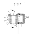
- la figure 3 est une vue en élévation d'une coupe radiale du frein à disque suivant la ligne III-III des figures 1 et 2.
- FIG. 1 is a side elevation view of the disc brake partially in vertical section along the line 1-1 of FIG. 2,
- FIG. 2 is a plan view of the disc brake with partial cutaway at the level of a baluster, and
- FIG. 3 is an elevation view of a radial section of the disc brake along the line III-III of FIGS. 1 and 2.
Le frein à disque tel que représenté sur les dessins annexés comporte un étrier 1 disposé à cheval par-dessus une partie de la périphérie d'un disque de frein 2 mobile en rotation autour d'un axe non représenté. Près de ses deux extrémités avant et arrière, l'étrier 1 est monté coulissant par l'intermédiaire de deux colonnettes 3,4 solidaires d'un support fixe 5 dans les paliers correspondants formés dans l'étrier 1 de façon à pouvoir coulisser parallèlement à l'axe du disque de frein 2. L'étrier 1 comporte une ouverture périphérique de montage 6 qui est de forme rectangulaire et qui est ménagée dans l'étrier 1 pour permettre le passage de la partie active des patins de friction extérieur 7 et intérieur 8. Le patin intérieur 8 coopère directement avec un moteur de commande 9 incorporé dans l'étrier 1 tandis que le patin extérieur coopère indirectement avec ledit moteur 9 en s'appuyant contre le nez 10 dudit étrier 1. Chaque patin de friction 7 et 8 comprend du côté de l'étrier 1 une plaque porte-garniture 11, 12 réalisée en un métal approprié ainsi que, du côté du disque de frein 2, une garniture de friction 13, 14 s'appliquant contre la face latérale correspondante du disque de frein 2 lorsque le moteur 9 est actionné.The disc brake as shown in the accompanying drawings comprises a caliper 1 disposed astride a portion of the periphery of a
Les côtés avant et arrière de l'ouverture de passage 6 de l'étrier 1 sont délimités respectivement par un bord de guidage 15 et 16 qui s'étend parallèlement à l'axe du disque de frein et qui coopère avec l'un des deux becs d'appui 17, 18 ou 19, 20 de la plaque porte-garniture 11 ou 12 du patin extérieur 7 ou du patin intérieur 8.The front and rear sides of the passage opening 6 of the caliper 1 are delimited respectively by a
Les deux patins de friction 7 et 8 sont disposés dans l'étrier 1 de part et d'autre du disque de frein 2 et sont accrochés sur l'étrier par l'intermédiaire des becs d'appui extrêmes 17, 18 et 19, 20 épousant la forme en V des bords de guidage 15 et 16. Ces patins 7 et 8 sont bloqués contre tout déplacement radial dans l'étrier 1 à l'aide d'une clavette de verrouillage 22 introduite dans l'intervalle délimité par un bord de guidage, par exemple 15, et les becs d'appui adjacents 17 et 19 des patins 7 et 8, une goupille 23 coopérant avec la clavette 22 et le bord de guidage correspondant 15, pour empêcher tout déplacement intempestif de ladite clavette 22. Il convient de préciser que la structure intérieure de l'étrier et le système de montage et de blocage des patins par rapport à l'étrier ne font pas partie de la présente invention et de surcroît sont décrits en détail dans le brevet français 2409423 de sorte qu'il n'est pas nécessaire de décrire davantage la structure générale du frein à disque faisant l'objet de la présente invention.The two
Selon l'invention, l'étrier 1 est placé, par ses extrémités frontales 24 et 25, sans jeu notable, entre une butée avant 26 et une butée arrière 27. Ces butées 26, 27 ont la forme d'une barre transversale s'étendant parallèlement à l'axe du disque de frein 2 au-dessus de celui-ci sur une longueur au moins égale à la largeur de l'espace occupé par les deux patins de friction 7 et 8. Chacune de ces butées 26, 27 est portée par un bras latéral 28, 29 solidaire d'un support fixe latéral 30 prévu sur les côtés intérieurs du disque de frein 2.According to the invention, the stirrup 1 is placed, by its
Le support fixe 30 pour les bras de support latéraux 28 et 29 des butées 26 et 27 peut être constitué par un support fixe indépendant ou peut être confondu avec le support fixe 5 dans lequel sont montées les colonnettes 3 et 4 de coulissement de l'étrier 1. Afin d'éviter tout jeu important entre l'étrier 1 et les deux butées 26 et 27, on prévoit sur la face frontale 24 et sur la face arrière 25 de l'étrier 1 deux têtes d'appui latérales 31, 32 et 33, 34 qui sont situées en face des extrémités de chaque butée 26 et 27. En particulier, le support fixe 30 et le support fixe 5 peuvent être réalisés directement dans le porte-fusée du véhicule.The
Le mode de réalisation précédemment décrit peut subir un certain nombre de modifications sans que l'on sorte pour cela du cadre de protection défini par les modifications annexées. Parmi les variantes on peut envisager le montage d'un manchon élastique entre les colonnettes et les alésages correspondants formant paliers dans l'étrier. Dans cette variante l'étrier par compression desdits manchons, viendra systématiquement en contact avec les butées 26, 27 pour transmettre intégralement le couple de freinage au support fixe 30, les colonnettes ne prennent dans ce cas pratiquement aucun couple et ne servent qu'au coulissement de l'étrier au fur et à mesure de l'usure des éléments de friction 6 et 8.The previously described embodiment may undergo a certain number of modifications without going beyond the protective framework defined by the appended modifications. Among the variants, it is possible to envisage mounting an elastic sleeve between the balusters and the corresponding bores forming bearings in the stirrup. In this variant the caliper by compression of said sleeves, will systematically come into contact with the
Claims (5)
Applications Claiming Priority (2)
| Application Number | Priority Date | Filing Date | Title |
|---|---|---|---|
| FR8300388 | 1983-01-12 | ||
| FR8300388A FR2539196B1 (en) | 1983-01-12 | 1983-01-12 | DISC BRAKE |
Publications (2)
| Publication Number | Publication Date |
|---|---|
| EP0115980A1 EP0115980A1 (en) | 1984-08-15 |
| EP0115980B1 true EP0115980B1 (en) | 1986-05-14 |
Family
ID=9284862
Family Applications (1)
| Application Number | Title | Priority Date | Filing Date |
|---|---|---|---|
| EP84400065A Expired EP0115980B1 (en) | 1983-01-12 | 1984-01-12 | Disc brake |
Country Status (8)
| Country | Link |
|---|---|
| US (1) | US4560036A (en) |
| EP (1) | EP0115980B1 (en) |
| JP (1) | JPH0733856B2 (en) |
| AU (1) | AU556489B2 (en) |
| DE (1) | DE3460129D1 (en) |
| ES (1) | ES284717Y (en) |
| FR (1) | FR2539196B1 (en) |
| YU (1) | YU984A (en) |
Families Citing this family (5)
| Publication number | Priority date | Publication date | Assignee | Title |
|---|---|---|---|---|
| DE4401843C2 (en) * | 1994-01-22 | 2003-04-30 | Continental Teves Ag & Co Ohg | Floating caliper for disc brakes |
| DE19743538A1 (en) † | 1997-10-01 | 1999-04-08 | Wabco Perrot Bremsen Gmbh | Sliding caliper disc brake |
| JP2002070898A (en) * | 2000-09-01 | 2002-03-08 | Nisshinbo Ind Inc | Pin-slide type disc brake device |
| US20050230197A1 (en) * | 2004-04-14 | 2005-10-20 | Jedele Philip N | One piece sliding brake caliper |
| US8973720B2 (en) * | 2012-08-17 | 2015-03-10 | Bendix Spicer Foundation Brake Llc | Disc brake pad mounting and retention system and method |
Family Cites Families (16)
| Publication number | Priority date | Publication date | Assignee | Title |
|---|---|---|---|---|
| FR1316440A (en) * | 1962-03-02 | 1963-01-25 | Teves Kg Alfred | Disc brake with partial brake linings |
| US3917032A (en) * | 1974-02-11 | 1975-11-04 | Gen Motors Corp | Single mount and guide pin for a caliper of a disc brake assembly |
| CA1091599A (en) * | 1976-09-02 | 1980-12-16 | Donald D. Johannesen | Disc brake and mounting therefor |
| FR2378209A1 (en) * | 1977-01-20 | 1978-08-18 | Dba | DISC BRAKE AND ELASTIC CLAMP FOR SUCH A BRAKE |
| FR2409423A1 (en) * | 1977-11-17 | 1979-06-15 | Dba | DISC BRAKE AND GUIDE KEY FOR SUCH A BRAKE |
| DE2757392A1 (en) * | 1977-12-22 | 1979-07-05 | Teves Gmbh Alfred | PARTIAL DISC BRAKE |
| DE2807125C2 (en) * | 1978-02-20 | 1986-06-26 | Alfred Teves Gmbh, 6000 Frankfurt | Floating-caliper partially lined disc brakes, in particular for motor vehicles |
| US4174769A (en) * | 1978-03-03 | 1979-11-20 | Societe Anonyme D.B.A. | Disc brake and a resilient clip for such a brake |
| US4274514A (en) * | 1978-08-28 | 1981-06-23 | The Bendix Corporation | Pin slider disc brake |
| DE2904118A1 (en) * | 1979-02-03 | 1980-09-04 | Teves Gmbh Alfred | PARTIAL DISC BRAKE, ESPECIALLY FOR MOTOR VEHICLES |
| FR2470291A1 (en) * | 1979-11-20 | 1981-05-29 | Dba | DISC BRAKE |
| JPS5686236U (en) * | 1979-12-06 | 1981-07-10 | ||
| US4310075A (en) * | 1980-03-10 | 1982-01-12 | The Bendix Corporation | Disc brake |
| JPS572937A (en) * | 1980-06-04 | 1982-01-08 | Matsushita Electric Ind Co Ltd | High frequency heating apparatus |
| JPS57156642U (en) * | 1981-03-30 | 1982-10-01 | ||
| FR2517399B1 (en) * | 1981-11-30 | 1986-12-05 | Dba | DISC BRAKE AND PAD FOR SUCH A BRAKE |
-
1983
- 1983-01-12 FR FR8300388A patent/FR2539196B1/en not_active Expired
- 1983-12-30 ES ES1983284717U patent/ES284717Y/en not_active Expired
-
1984
- 1984-01-05 YU YU00009/84A patent/YU984A/en unknown
- 1984-01-05 US US06/568,478 patent/US4560036A/en not_active Expired - Fee Related
- 1984-01-10 AU AU23179/84A patent/AU556489B2/en not_active Expired
- 1984-01-12 JP JP59002783A patent/JPH0733856B2/en not_active Expired - Lifetime
- 1984-01-12 EP EP84400065A patent/EP0115980B1/en not_active Expired
- 1984-01-12 DE DE8484400065T patent/DE3460129D1/en not_active Expired
Also Published As
| Publication number | Publication date |
|---|---|
| AU2317984A (en) | 1984-07-19 |
| FR2539196B1 (en) | 1986-02-28 |
| YU984A (en) | 1988-04-30 |
| AU556489B2 (en) | 1986-11-06 |
| ES284717U (en) | 1985-07-16 |
| JPS59137629A (en) | 1984-08-07 |
| US4560036A (en) | 1985-12-24 |
| JPH0733856B2 (en) | 1995-04-12 |
| EP0115980A1 (en) | 1984-08-15 |
| FR2539196A1 (en) | 1984-07-13 |
| DE3460129D1 (en) | 1986-06-19 |
| ES284717Y (en) | 1986-04-01 |
Similar Documents
| Publication | Publication Date | Title |
|---|---|---|
| EP0104108B2 (en) | Support arm for a motorized wheel | |
| EP0030502B1 (en) | Disc brake | |
| EP0772749B1 (en) | Brake pad and disc | |
| FR2548302A1 (en) | IMPROVED MULTIDISC BRAKE | |
| EP0115980B1 (en) | Disc brake | |
| FR2512904A1 (en) | DISC BRAKE | |
| EP0133389B1 (en) | Disc brake with a removable caliper reinforcing arm | |
| EP0059128A1 (en) | Pad spring for disc brakes | |
| EP0366509B1 (en) | Brake with two fixedly spaced discs | |
| EP1451482B1 (en) | Disc brake caliper for vehicle | |
| EP0117192B1 (en) | Disc-brake | |
| EP1064471B1 (en) | Disk brake damped by shearing | |
| EP0966620B1 (en) | Hybrid multiple disc brake | |
| EP0830519A1 (en) | Disc brake using a rotationally biased pad | |
| FR2549182A1 (en) | DEVICE FOR CONTROLLING DISC BRAKE FOR MOTOR VEHICLES OR TRAILERS | |
| EP0118337B1 (en) | Disc-brake | |
| EP0114549B1 (en) | Disc brake | |
| FR2578931A1 (en) | SLIDING CALIPER DISC BRAKE | |
| EP0648316B1 (en) | Spring retainer system | |
| EP1626192B1 (en) | Disc brake for a vehicle | |
| FR2965027A1 (en) | Disk brake for motor vehicle, has outboard disk brake pad integrated with outer arm of brake caliper by fixation screws, to allow guided displacement of brake caliper with respect to fixed support by outboard disk brake pad | |
| EP2861479B1 (en) | Off-centre yoke for a motor vehicle steering system | |
| EP0645551A1 (en) | Floating caliper disc brake | |
| EP0120738B1 (en) | Sliding caliper disc-brake | |
| EP0132721A1 (en) | Device for connecting a ski lift seat or cabin to a rope having a rolling surface for sheaves |
Legal Events
| Date | Code | Title | Description |
|---|---|---|---|
| PUAI | Public reference made under article 153(3) epc to a published international application that has entered the european phase |
Free format text: ORIGINAL CODE: 0009012 |
|
| 17P | Request for examination filed |
Effective date: 19840123 |
|
| AK | Designated contracting states |
Designated state(s): DE GB IT SE |
|
| RAP1 | Party data changed (applicant data changed or rights of an application transferred) |
Owner name: BENDIX FRANCE |
|
| ITF | It: translation for a ep patent filed |
Owner name: ING. ZINI MARANESI & C. S.R.L. |
|
| GRAA | (expected) grant |
Free format text: ORIGINAL CODE: 0009210 |
|
| RAP1 | Party data changed (applicant data changed or rights of an application transferred) |
Owner name: BENDIX FRANCE |
|
| AK | Designated contracting states |
Kind code of ref document: B1 Designated state(s): DE GB IT SE |
|
| REF | Corresponds to: |
Ref document number: 3460129 Country of ref document: DE Date of ref document: 19860619 |
|
| PLBE | No opposition filed within time limit |
Free format text: ORIGINAL CODE: 0009261 |
|
| STAA | Information on the status of an ep patent application or granted ep patent |
Free format text: STATUS: NO OPPOSITION FILED WITHIN TIME LIMIT |
|
| 26N | No opposition filed | ||
| ITTA | It: last paid annual fee | ||
| EAL | Se: european patent in force in sweden |
Ref document number: 84400065.3 |
|
| REG | Reference to a national code |
Ref country code: GB Ref legal event code: IF02 |
|
| PGFP | Annual fee paid to national office [announced via postgrant information from national office to epo] |
Ref country code: GB Payment date: 20021218 Year of fee payment: 20 |
|
| PGFP | Annual fee paid to national office [announced via postgrant information from national office to epo] |
Ref country code: SE Payment date: 20030123 Year of fee payment: 20 |
|
| PGFP | Annual fee paid to national office [announced via postgrant information from national office to epo] |
Ref country code: DE Payment date: 20030225 Year of fee payment: 20 |
|
| PG25 | Lapsed in a contracting state [announced via postgrant information from national office to epo] |
Ref country code: GB Free format text: LAPSE BECAUSE OF EXPIRATION OF PROTECTION Effective date: 20040111 |
|
| REG | Reference to a national code |
Ref country code: GB Ref legal event code: PE20 |
|
| EUG | Se: european patent has lapsed |