EP0115417A2 - Hydraulically damped mounting device - Google Patents
Hydraulically damped mounting device Download PDFInfo
- Publication number
- EP0115417A2 EP0115417A2 EP84300406A EP84300406A EP0115417A2 EP 0115417 A2 EP0115417 A2 EP 0115417A2 EP 84300406 A EP84300406 A EP 84300406A EP 84300406 A EP84300406 A EP 84300406A EP 0115417 A2 EP0115417 A2 EP 0115417A2
- Authority
- EP
- European Patent Office
- Prior art keywords
- mounting device
- diaphragm
- liquid
- partition
- hydraulically damped
- Prior art date
- Legal status (The legal status is an assumption and is not a legal conclusion. Google has not performed a legal analysis and makes no representation as to the accuracy of the status listed.)
- Granted
Links
Images


Classifications
-
- F—MECHANICAL ENGINEERING; LIGHTING; HEATING; WEAPONS; BLASTING
- F16—ENGINEERING ELEMENTS AND UNITS; GENERAL MEASURES FOR PRODUCING AND MAINTAINING EFFECTIVE FUNCTIONING OF MACHINES OR INSTALLATIONS; THERMAL INSULATION IN GENERAL
- F16F—SPRINGS; SHOCK-ABSORBERS; MEANS FOR DAMPING VIBRATION
- F16F13/00—Units comprising springs of the non-fluid type as well as vibration-dampers, shock-absorbers, or fluid springs
- F16F13/04—Units comprising springs of the non-fluid type as well as vibration-dampers, shock-absorbers, or fluid springs comprising both a plastics spring and a damper, e.g. a friction damper
- F16F13/26—Units comprising springs of the non-fluid type as well as vibration-dampers, shock-absorbers, or fluid springs comprising both a plastics spring and a damper, e.g. a friction damper characterised by adjusting or regulating devices responsive to exterior conditions
-
- F—MECHANICAL ENGINEERING; LIGHTING; HEATING; WEAPONS; BLASTING
- F16—ENGINEERING ELEMENTS AND UNITS; GENERAL MEASURES FOR PRODUCING AND MAINTAINING EFFECTIVE FUNCTIONING OF MACHINES OR INSTALLATIONS; THERMAL INSULATION IN GENERAL
- F16F—SPRINGS; SHOCK-ABSORBERS; MEANS FOR DAMPING VIBRATION
- F16F13/00—Units comprising springs of the non-fluid type as well as vibration-dampers, shock-absorbers, or fluid springs
- F16F13/04—Units comprising springs of the non-fluid type as well as vibration-dampers, shock-absorbers, or fluid springs comprising both a plastics spring and a damper, e.g. a friction damper
- F16F13/06—Units comprising springs of the non-fluid type as well as vibration-dampers, shock-absorbers, or fluid springs comprising both a plastics spring and a damper, e.g. a friction damper the damper being a fluid damper, e.g. the plastics spring not forming a part of the wall of the fluid chamber of the damper
- F16F13/08—Units comprising springs of the non-fluid type as well as vibration-dampers, shock-absorbers, or fluid springs comprising both a plastics spring and a damper, e.g. a friction damper the damper being a fluid damper, e.g. the plastics spring not forming a part of the wall of the fluid chamber of the damper the plastics spring forming at least a part of the wall of the fluid chamber of the damper
- F16F13/10—Units comprising springs of the non-fluid type as well as vibration-dampers, shock-absorbers, or fluid springs comprising both a plastics spring and a damper, e.g. a friction damper the damper being a fluid damper, e.g. the plastics spring not forming a part of the wall of the fluid chamber of the damper the plastics spring forming at least a part of the wall of the fluid chamber of the damper the wall being at least in part formed by a flexible membrane or the like
-
- F—MECHANICAL ENGINEERING; LIGHTING; HEATING; WEAPONS; BLASTING
- F16—ENGINEERING ELEMENTS AND UNITS; GENERAL MEASURES FOR PRODUCING AND MAINTAINING EFFECTIVE FUNCTIONING OF MACHINES OR INSTALLATIONS; THERMAL INSULATION IN GENERAL
- F16F—SPRINGS; SHOCK-ABSORBERS; MEANS FOR DAMPING VIBRATION
- F16F13/00—Units comprising springs of the non-fluid type as well as vibration-dampers, shock-absorbers, or fluid springs
- F16F13/04—Units comprising springs of the non-fluid type as well as vibration-dampers, shock-absorbers, or fluid springs comprising both a plastics spring and a damper, e.g. a friction damper
- F16F13/06—Units comprising springs of the non-fluid type as well as vibration-dampers, shock-absorbers, or fluid springs comprising both a plastics spring and a damper, e.g. a friction damper the damper being a fluid damper, e.g. the plastics spring not forming a part of the wall of the fluid chamber of the damper
- F16F13/20—Units comprising springs of the non-fluid type as well as vibration-dampers, shock-absorbers, or fluid springs comprising both a plastics spring and a damper, e.g. a friction damper the damper being a fluid damper, e.g. the plastics spring not forming a part of the wall of the fluid chamber of the damper characterised by comprising also a pneumatic spring
Definitions
- the present invention relates to hydraulically damped mounting devices.
- the isolator In a structure where it is desired to prevent the vibration of a piece of machinery (reciprocating engine for'example) being transmitted to another part, it is common to provide an isolator (or mounting) between the two parts of the structure, the isolator being a combined spring and damper.
- the present invention is concerned with a mounting device where the damping is achieved at least partially hydraulically. It finds applications, for example, in mounting an engine in a vehicle. In general such mountings have to function under different types of vibrations, which may vary both in frequency and amplitude. In general, small amplitude vibrations have a high frequency and large amplitude vibrations have a low frequency, but this is not always the case due to e.g. resonances in the system. The resonances may arise both from the structure itself and from properties of the mounting device.
- Conventional mountings usually have an all- elastomeric construction to provide a compromise between the requirement of high damping to control and limit large amplitudes at predominantly low frequency and the requirement at low damping to reduce the forces transmitted at small amplitude and high frequency.
- the present invention overcomes the need to compromise by providing two stage damping, i.e. to achieve a large degree of damping for high amplitude vibration but negligible damping at low amplitudes.
- flexing of the diaphragm absorbed the movement of hydraulic fluid caused by the change in the volume of the working chamber.
- this movement was was insufficient to take up all the volume change and hydraulic fluid moved between the working chamber and the compensation chamber through the aperture, the compensation chamber expanding or contracting by deformation of the second deformable wall to compensate for the movement of fluid.
- the fact that part of the second deformable wall was free to move is important to ensure that the compensation chamber acts as such.
- the volume of the compensation chamber must be variable in such a way as to respond to changes of pressure within the compensation chamber.
- the present invention seeks to provide a device which has the capacity for the isolation of high frequency as well as low frequency vibrations, independent of their amplitude. Furthermore it permits, at least in some embodiments, "tuning" of the response of the device to the expected behaviour of the vehicle or other structure into which it is to be incorporated.
- the main factor controlling the low frequency response is the resistance to movement of liquid in the passage between the working chamber and the compensation chamber.
- EP-A-0027751 and EP-A-0040290 attempt to control the low frequency response by suitable design of the passage, but can never.achieve isolation of this response because there must always be some transmission of vibration from the working chamber to the compensation chamber via the flexible membrane.
- To isolate the low frequency response it is necessary for the only pressure transmission between the chambers to be via the passage and this would entail a rigid partition.
- the low frequency response by which is meant the response between about 5 and 20 Hz, may then be controlled by suitable selection of the parameters of the passage.
- the use of a rigid partition would eliminate the method used in the prior art for controlling the high frequency response.
- the inventor of the present invention has realised that the high frequency response may be controlled if the pressure changes of the liquid in the working chamber were transmitted to a gas. Since the gas would respond more rapidly than the liquid to pressure changes, this would give a suitable high frequency response. Therefore the present invention proposes that a flexible diaphragm is provided in the working chamber, the diaphragm acting as a barrier between the liquid and a gas.
- the first possible arrangement is for the diaphragm to define part of a closed gas pocket, which may, for example be located on the partition. Relative movement of the anchor points causes a change in volume of the working chamber, which change is transmitted to the gas pocket. Since the pocket is closed, work must be expended in causing it to expand or contract and thus an air-spring is formed. This air spring controls the high frequency response of the mounting device.
- a problem with such an arrangement is that thermal expansion or contraction of the gas pocket will cause the diaphragm to be biased from its normal position, which would have a detrimental effect on the behaviour of the mounting device. Changes of temperature are likely to occur if the mounting device is used to mount the engine of a motor vehicle, and hence it is desirable to provide some means of temperature compensation.
- One arrangement in which this is achieved proposes providing a bleed orifice leading from the gas pocket to the ambient atmosphere.
- the effective aperture of the bleed orifice is sufficiently small for the gas pocket to act as a closed pocket under high frequency changes, but to permit thermal equalisation of the pressure inside the gas pocket. Changes in pressure due to thermal effects occur much more slowly than the vibrations which affect the mounting device when in normal use.
- the characteristics of the mounting device may be "tuned" to give a desired frequency response.
- a development of this is to make the effective aperture adjustable in response to e.g. engine frequency, to provide a mounting device with a variable frequency response.
- An alternative, or additional, way of compensating for pressure changes in the gas pocket is to make the volume of the gas pocket controllable.
- thermal compensation provides a bleed orifice from the gas pocket which leads to a gas reservoir, the pressure in which is affected by the liquid pressure in the compensation chamber. Then, thermal expansion of the gas pocket causes a corresponding increase in pressure in the liquid in the compensation chamber, and hence in the liquid in the working chamber, thus equalising pressure across the diaphragm.
- the diaphragm may be mounted e.g. on the deformable wall joining the anchor points.
- At least part of the deformable wall joining the two anchor points is a resilient spring.
- the resilient spring forms the or a part of the deformable wall of the compensation chamber, and the other deformable wall is a flexible bellows.
- This arrangement has the advantage that the resistance to movement of the anchor points is determined primarily by the gas pocket and the movement of liquid through the passage linking the working and compensation chambers. This gives a particularly favourable high frequency response.
- a first embodiment of a mounting device has a boss 1 connected via a fixing bolt 2 to one of the parts of the structure.
- the other part of the structure is connected to a bolt 3 fixed on a generally U-shaped cup 4.
- Inside the cup 4 is a deformable wall formed by a flexible bellows 5 which receives adjacent the rim of the cup 4 a rigid partition 6.
- the bellows 5 also has a splayed portion 8 adjacent the rim of the cup 4 which overlaps that rim and the partition 6.
- This splayed portion 8 abuts against an annular surface of a resilient spring 9 made of e.g. rubber which extends from that annular surface over the partition and which has a recess 10 which receives the boss 1.
- An annular bracket 11 extends into the resilient spring 9 and has a part 12 extending over the rim of the cup 4 thereby securing the resilient spring 9 to the cup 4. This also has the effect of forcing the resilient spring 9 against the splayed portion 8 of the bellows thereby pressing that splayed portion against the partition 6.
- a working chamber 13 is formed between the resilient spring 9 and the partition 6, and a compensation chamber or reservoir 14 is formed between the partition and the bellows 5.
- the working chamber 13 and the reservoir 14 are filled with hydraulic fluid.
- the partition has a passage 15 extending through it communicating at one end with the working chamber 13 and at the other with the reservoir 14. As shown in the Figure the passage 15 is long and extends around the circumference of the partition 6.
- a diaphragm 16 made of e.g. rubber like material extends over a portion of surface 17 of the partition 6 in the chamber 13 and has gas, such as air, in the space 18 between it and the surface 17 of the partition 6.
- a cover 19 having apertures 20 therein extends in the chamber 13 over the diaphragm 16. As shown in Figure 1, the partition 6 is formed into two parts with the cover 19 being integral with the upper part.
- the boss 1 moves towards or away from the partition 6.
- the spring element flexes and reduces (increases) the volume of the working chamber.
- the inertia of the liquid in the passage 15 prevents the vibration being transmitted to the reservoir 14 and the pressure increase (or decrease) in the working chamber is transmitted to the diaphragm 16 via the apertures'20.
- the diaphragm 16 is forced towards (away from) the surface 17 of the partition, compressing (expanding) the air or other gas in the pocket 18 formed between the diaphragm 16 and the surface 17.
- the gas pressure in the pocket 18 and the resistance to movement of the diaphragm 16 itself acts as a gas spring being activated'by the oscillations. Due to the compression (expansion) of the air, the damping effect is applied to the vibrations, which increases with increasing amplitude oscillations. There is a limit to this. To prevent damage to the diaphragm 16, it is important that it is constrained from vibrating with too great an amplitude, and this is achieved by the limiting effect of surface 17 and cover 20.
- the liquid moves more freely through the passage 15 and the damping effect is controlled by the length and dimensions of the passage and by the viscosity of the liquid.
- the device can be designed to suit the particular application envisaged.
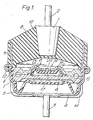
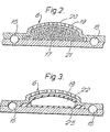
- Figures 2 and 3 show alternative configurations of the diaphragm.
- the gas pocket is formed by cells in a body 21 of closed cell foam rubber. Small amplitude oscillations are communicated to the body 21 through holes 20 in the cover 19 and expansion or contraction of the cells of the body absorb the vibrations. Large amplitude vibrations cause the body to be compressed against the surface 17 of the partition or to expand against the cover 19 so that the vibration causes fluid movement through the aperture 15 with a resulting high level of damping.
- the body may be mounted at any convenient location within the working chamber 13 or even loose within the chamber. In this latter case, however, some constraints would be necessary to prevent the foam rubber body blocking the aperture 15 and also to prevent over-expansion of the cells which could burst them.
- the gas pocket is formed by an encapsulated gas space 22 within a moulded capsule 23.
- the capsule 23 is held in the partition 6 and over-expansion is prevented by cover 19.
- FIG. 4 A second embodiment of the present invention will now be described, with reference to Figure 4, in which a bleed orifice leads from the pocket 18 to the ambient atmosphere.
- Parts of the mounting device similar to those of the first embodiment shown in Figure 1 are indicated by the same reference numerals and will not be described further.
- the partition 6 comprises a plate 24 which provides a rigid barrier between working chamber 13 and reservoir 14 and has a flange 25 at its outer periphery which is received between portions 26 and 27 of bellows 5 and resilient spring 9 respectively.
- the flange 25 and the splayed portions 26 and 27 are held together by part 12 of the annular bracket 11 which extends over the rim of cup 4.
- the upper surface of the plate 24 has a central recess 28 formed in it which has a step 29 in its radially outer edge, which step 29 acts as a shoulder for receiving a lower perforated plate 30.
- the perforated plate 30 has a depression at its central portion and the diaphragm 16 rests on the thicker portions at the radially outer edge of the plate to be supported clear of the central part of the-perforated plate 30.
- a gas pocket 18 is formed bounded by the recess 28 and the diaphragm 16.
- a recess in the form of a part-annular channel 31 is formed in the plate 24 radially outwardly of the central recess 26. It is this part-annular channel 31 which forms the passage 15 between the chamber 13 and the reservoir 14.
- An upper perforated plate 32 is secured on top of the lower plate 24, by lip 33, over the diaphragm 16. Part of the upper plate 32 extends over the channel 31 to form the top of the passage 15. An aperture 34 in the upper plate and a corresponding aperture (not shown) in the lower plate permit liquid to enter the passage 15.
- the lower surface of the upper plate 32 has a depression therein, and the peripheral portions of the upper plate 32 abut against the diaphragm 16 to clamp the diaphragm 16 between the lower plate 30 and the upper plate 32.
- the diaphragm 16 is pressed against the lower perforated plate 30 (or the upper perforated plate 32) and continued movement of the boss 1 is possible only by movement of fluid from the chamber 13 to the reservoir 14 (or vice versa) through the aperture 15.
- the main damping effect is given by the movement of the liquid through the passage 15.
- the purpose of the lower perforated plate 30 is to limit the oscillations of the diaphragm 16 in the downward direction but permit the diaphragm 16 to influence the air in the pocket 18.
- a plurality of projections may be provided on the lower surface 37 of the recess 26 which extends sufficiently far from that surface to limit the movement of the diaphragm if the diaphragm contacts their upper surface. The pocket 18 is then formed by the space between such projections.
- the mounting may be subject to significant fluctuations in ambient temperature, e.g. when used in a motor vehicle as an engine mounting there would be a significant temperature difference in the mounting when the engine has been running for a long time as compared to the temperature when the engine is not in use. Such temperature variations would cause expansion or contraction of the air in the space 18 and would bias the diaphragm 16 either towards the upper perforated plate 32 or towards the lower perforated plate 30. As explained previously, this biasing of the diaphragm 16 would affect the performance of the mounting as it would limit the possible movement of the diaphragm in one of its directions of movement.
- a bleed orifice 38 is provided in the plate 24 extending from the recess 28, through the flange 25 and communicating with an opening 39 in the part of the bracket 11 which extends over the rim of the cup 4.
- This bleed orifice 38 is sufficiently narrow to prevent significant movement of air during vibrations of the diaphragm 16 but permits compensation for expansion or contraction of the air in pocket 18.
- the second embodiment is therefore preferred because it permits such compensation.
- the dimensions of the bleed orifice 38 may be selected to give the desired characteristic to the gas spring formed by the pocket 18. However, in order for the bleed orifice 38 to restrict gas movement when vibrations are applied to the mounting device, it is necessary that the maximum effective aperture of the bleed orifice must be related to its length. It has been found that satisfactory results are achieved if the length of the bleed orifice 38 is at least five times its effective diameter.
- Another parameter that is important in satisfactory operation of the mounting device is the ratio of the area of the diaphragm 16 to the effective area of the resilient spring 9, i.e. the area of a piston for which movement over a given distance would cause a pressure change in the working chamber 13 equivalent to the pressuze change produced by a movement of the boss 1 over the same distance. If the area of the diaphragm 16 is less than the effective area of the resilient spring 9, a given movement ofthe boss 1 appears as a magnified movement of the diaphragm 16. This magnification effect is important because it is a factor in determining the amplitude of vibration at which the diaphragm 16 is forced against the lower or upper perforated plates 30 and 32, respectively. It has been found that the ratio of the area of the diaphragm 16 to the effective area of the resilient spring 9 is desirably about 1:5.
- a third embodiment is proposed in which the effective aperture of the bleed orifice is controlled.
- the bleed orifice 38 terminates in a valve 39.
- the third embodiment is generally similar to the second embodiment shown in Figure 4 and corresponding parts are indicated by the same reference numerals.
- the valve 39 comprises an obdurator element 40, the position of which is controlled by an actuator 41.
- the obdurator element 40 terminates in a tapered portion 42, the taper of which corresponds generally to the taper of the outlet 43 of the bleed orifice 38.
- the actuator 41 controls the position of the obdurator element 40 to control the gap between the tapered portion 42 and the outlet 43. Since it is this gap which determines the effective aperture of the bleed orifice 38, its diameter over the major part of its length is not as critical as is the second embodiment and in general will be of greater diameter.
- the actuator 41 may be controlled by a frequency signal derived e.g. from the engine of a vehicle in which the device is mounted, thus enabling the frequency response of the device to be adjusted in response to the dominant frequency of the oscillations occurring between the anchor points of the device.
- the fourth embodiment of the present invention shown in Figure 6, exemplifies one way of achieving volume control.
- the mounting device of the fourth embodiment is generally similar to the second embodiment, except that the gas pocket 18 is defined between the diaphragm 16 and a flexible membrane 42. There is a space 43 between the flexible membrane 42 and the inner surface 44 of the partition 6, and this space 43 is filled with a hydraulic fluid.
- the mounting device may be similar to the second embodiment shown in Figure 4, and corresponding parts are indicated by the same reference numerals.
- a passageway 45 leads from the space 43 to a chamber 46 containing a piston 47.
- the position of the piston 47 in the chamber 46 is controlled by an actuator 48. Movement of the piston 47 is transmitted via the hydraulic fluid to the membrane 42 which flexes so as to increase or decrease the volume of the gas pocket 18.
- the.spring effect of the gas varies, thereby varying the characteristics of the mounting device.
- the high frequency vibration is absorbed within the gas pocket 18 because the hydraulic fluid is relatively incompressible so that the membrane 42 acts as a rigid barrier to vibration of the gas in the pocket 18.
- the gas pocket 18 may be closed, as in the first embodiment, but it is preferable that a bleed orifice be provided to permit compensation for temperature variations. It is even possible to provide a bleed orifice with a variable effective aperture, as in the third embodiment.
- control of the effective aperture of the bleed orifice in the third embodiment, or the control of the effective volume of the gas pocket in the fourth embodiment enable the characteristics of the spring effect of the gas pocket to be "tuned” to smooth out high-frequency resonances. Indeed, it is possible to "tune" the response so that the total assembly has an uneven response with a decrease in stiffness at a frequency corresponding to the resonant frequency of the vehicle as a whole (usually due to the body of the vehicle).
- the fifth embodiment of the present invention illustrates another way to compensate for temperature change.
- a bleed orifice 49 leads from the gas pocket 18, but instead of leading to the ambient atmosphere as in the second embodiment, it leads to a gas reservoir chamber 50 on the other side of the partition 6.
- the gas reservoir chamber 50 is bounded by the surface 51 of the partition 6 opposite to the diaphragm 16 and by the bellows 5.
- the compensation chamber or reservoir 52 for the hydraulic fluid is then defined between the bellows 5 and the inner surface of the cup 4. Otherwise the fifth embodiment may be similar to the second embodiment and corresponding parts are indicated by the same reference numerals.
- the effective diameter of the bleed orifice 49 is sufficiently small to prevent significant gas movement when vibrations are applied to the mounting device, but permitting thermal equalisation (which is a relatively slow effect).
- the effective aperture of the bleed orifice may be selected to give particular response characteristics to the device.
- the diaphragm is mounted on the partition, so that the gas pocket is defined between the diaphragm and a surface of the partition. This is not essential, however, and the diaphragm may be at any convenient location within the working chamber.
- Figure 8 shows a sixth embodiment of the present invention in which the diaphragm is housed entirely within the boss 1 and shape of the partition 6 is greatly simplified. Otherwise the mounting is similar to the other embodiments and the same reference numerals are used where appropriate.
- the partition 6 is a flat plate extending between the working chamber 13 and the reservoir 14 and its radially outer edge 53 is held between portions 26 and 27 of the bellows 5 and resilient spring 9 respectively.
- the passage 15 is formed by a part-annular duct in the partition 6 communicating at one end with the chamber 13 and at the other with the reservoir 14.
- the boss 1 has a recess 54 which has a perforated wall 55 extending across it at an intermediate deptn in the recess 54.
- a second plate 56 extends across the recess 54 at a depth closer to the opening 57 of the recess than the plate 55.
- a diaphragm 58 is held between these two plates 55 and 56, and the recess 54 and the diaphragm 58 define a gas pocket 59.
- Holes 60 are provided in the plates 55 and 56 so that one surface of the diaphragm 58 defines a boundary of the pocket 59 in the recess 54 and the other surface of the diaphragm 58 is in contact with the fluid in the working chamber 13.
- this mounting device is similar to that of the previous embodiments.
- high frequency vibrations are transmitted to the boss 1, there is fluid movement through the holes 44 in the plate 41 to cause the diaphragm 16 to move towards, or away from, that plate.
- high frequency oscillations are absorbed by the diaphragm 58, whilst at low frequencies the movement of fluid through the passage 15 generates a large damping force.
- the gas pocket 59 may be closed, as in the first embodiment, but it is preferable that a bleed orifice 61 is provided in the boss 1 to permit thermal expansion or contraction of the air in the pocket 59, as in the second embodiment.
- the deformable wall connecting the two anchor points is a resilient spring. This is also true of the prior art constructions described previously. However, the inventor of the present invention has discovered that, because high frequency vibrations may be absorbed by a gas spring, an alternative construction is possible in which the anchor points are connected by a deformable, but inelastic element. There is then little resistance to relative movement of the anchor points except due to the gas spring and fluid damper effects of the mounting device.
- the high frequency response will be affected greatly by the response of the resilient spring. If, however, the connection of the two anchor points is flexible but inelastic, the high frequency response will be determined entirely by the movement of the diaphragm. At lower frequencies, the fluid moves through the passage in the partition giving a large damping effect.
- a resilient spring be provided as one wall of the compensation chamber.
- the diaphragm and gas pocket are designed to have a pressure-displacement characteristic with a first region, corresponding to very small deflections, in which the deflection produced by a given change in pressure is small, a second region in which the deflection with a given change of pressure is large and a third region, corresponding to large deflections, in which again the deflection for a given change in pressure is small.
- the mounting device is then operated with a static deflection at approximately the mid-point of the second region.
- the characteristic of the diaphragm and gas pocket may have a step-like characteristic with increasing pressure causing no deflection until a first pressure at which the characteristic changes to one of shallow slope where small changes in pressure cause a very large deflection until a predetermined deflection is reached, beyond which no deflection is possible.
- the range of possible deflections entirely within the slightly sloping region should be sufficient to absorb small amplitude vibrations (corresponding to the normal running vibrations of the engine when the mounting device is used as an engine mounting).
- the hydraulically damped mounting device of the seventh embodiment has a boss 1 connected via a fixing bolt 2 to one of the parts of the structure (the fixing bolt 2 forming an anchor point), the other part of the structure being connected to an anchor point in the form of a support 62 at the side of the mounting device.
- the boss 1 is connected to the support 62 by a flexible inelastic member 63 made of, for example, reinforced rubber.
- the supports 62 have an upper part 64 which extends over a bead 65 of the inelastic member 63 and a lower part 66 with a step 67 on which rests a partition 6.
- the partition is held in place by the entrapment of its outer edge between the bead 65 and the step 67, with the bead 65 in turn held by the upper part 64 of the support 62.
- the partition, the inelastic member 63 and the boss 1 form the working chamber 13 of the mounting device.
- the lower part 66 of the support 62 has an annular wall 68 at the opposite side to the inelastic member 63 and this annular wall 68 is connected via a resilient spring 69 to a rigid cup 70.
- the partition 6, the annular wall 68, the resilient spring 69 and the cup 70 form a compensation chamber or reservoir 14.
- the cup 70 is not essential and the resilient spring 69 may extend completely across the annular wall 68.
- the working chamber 13 and the reservoir 14 control hydraulic fluid in the mounting device and are in fluid communication via a passage 15.
- the passage 15 may be a short direct passageway because damping is provided by the resistanc to expansion of the reservoir 14 provided by the resilient spring 69. It is also possible to make the passage 15 long relative to its diameter by providing a part-annular duct extending around the partition 6 which communicates at one end with the working chamber 13 and at the other end with the reservoir 14.
- the partition 6 has a depression 71 and a diaphragm 72 extends across the top of the depression 71 to define a gas pocket 73.
- the diaphragm 72 consists of a rigid disc 74, the periphery of which is connected to the partition by a flexible annulus 75. Flanges 76 and 77 above and below the diaphragm 72 prevent excessive movement.
- the annulus 75 may be resilient to resist movement . of the disc 74 or optionally the annulus may be freely flexible and the disc 74 be biased to a central position between the flanges 76 and 77 by a helical spring 78. This gives a more linear characteristic over the effective travel of the disc 74.
- the gas pocket 73 may be closed or a bleed orifice 79 may be provided extending from the gas pocket 73 to ambient atmosphere. The effective aperture of the bleed orifice 79 may be controlled, as in the third embodiment. If desired, the diaphragm 72 may be mounted in the boss 1 as in the sixth embodiment.
- the disc 74 Under static load the disc 74 is biased to a central point between the flanges 76,77.
- the inelastic member 63 offers virtually no resistance to movement and so the vibrations are transmitted directly to the liquid in the working chamber 13 causing a change in pressure within that chamber 13.
- the disc 74 is displaced from its central position, but as the slope of its pressure-displacement characteristic at the point is very small, the variations in pressure are absorbed by the displacement of the disc 74 and such absorption occurs quickly giving a good high frequency response.
- the vibration of the boss 1 is transmitted directly to the diaphragm 72 and the volume of the gas pocket 73 varies to compensate for the vibration. Therefore, the boss 1 is effectively isolated from the rest of the mounting device and little or no damping force is transmitted to the boss 1.
- the mounting device behaves as if it were a spring with a very small stiffness.
- the present invention provides a hydraulically damped mounting device with an improved high frequency response.
- the mounting device may be considered as the parallel connection of a spring (formed by the gas pocket) and a damper (formed by the passage and the reservoir).
- the use of an elongate passage is equivalent to a mass on the damper.
- the "softness" of the spring is determined by the design of the gas pocket.
- the damper is disconnected at amplitudes less than a predetermined amount.
Landscapes
- Engineering & Computer Science (AREA)
- General Engineering & Computer Science (AREA)
- Mechanical Engineering (AREA)
- Combined Devices Of Dampers And Springs (AREA)
Abstract
Description
- The present invention relates to hydraulically damped mounting devices.
- In a structure where it is desired to prevent the vibration of a piece of machinery (reciprocating engine for'example) being transmitted to another part, it is common to provide an isolator (or mounting) between the two parts of the structure, the isolator being a combined spring and damper. The present invention is concerned with a mounting device where the damping is achieved at least partially hydraulically. It finds applications, for example, in mounting an engine in a vehicle. In general such mountings have to function under different types of vibrations, which may vary both in frequency and amplitude. In general, small amplitude vibrations have a high frequency and large amplitude vibrations have a low frequency, but this is not always the case due to e.g. resonances in the system. The resonances may arise both from the structure itself and from properties of the mounting device.
- Conventional mountings usually have an all- elastomeric construction to provide a compromise between the requirement of high damping to control and limit large amplitudes at predominantly low frequency and the requirement at low damping to reduce the forces transmitted at small amplitude and high frequency. The present invention overcomes the need to compromise by providing two stage damping, i.e. to achieve a large degree of damping for high amplitude vibration but negligible damping at low amplitudes.
- In UK 811748 a mounting was proposed which attempted to achieve this aim. It consisted of a first anchor point to be attached to one part of the structure, a second anchor point to be attached to another part of the structure, and a deformable wall in the form of a resilient spring element connecting together the fixing points. A surface of a flexible partition rigidly associated with the first anchor point defined, together with the spring element, a working chamber containing liquid. The working chamber communicated, via an aperture in the flexible partition with a compensation chamber or reservoir. The compensation chamber was bounded by a second deformable wall in the form of a bellows so that the volume of the compensation chamber was determined by the liquid pressure in it, which in turn was determined by the volume of the working chamber. Vibrations of one partofthe structure relative to the other caused the anchor points to vibrate relative to each other and this caused flexing of the spring element thereby changing the volume of the working chamber. For small amplitude vibrations, flexing of the diaphragm absorbed the movement of hydraulic fluid caused by the change in the volume of the working chamber. For high amplitude oscillation, however, this movement was was insufficient to take up all the volume change and hydraulic fluid moved between the working chamber and the compensation chamber through the aperture, the compensation chamber expanding or contracting by deformation of the second deformable wall to compensate for the movement of fluid. The fact that part of the second deformable wall was free to move is important to ensure that the compensation chamber acts as such. The volume of the compensation chamber must be variable in such a way as to respond to changes of pressure within the compensation chamber. Thus, the structure damped large oscillations but left small oscillations relatively undamped.
- Numerous attempts have been made to improve the mounting of GB-A-811748. It is known from EP-A-0027751 and EP-A-0040290 to form the partition as a flexible membrane in a rigid support fixed to the first anchor point. Instead of an aperture in the flexible membrane, a long passage of small cross section but of significant volume is provided in the rigid support connecting the working and compensation chambers. The flexible membrane is to absorb low amplitude vibrations, namely those whose amplitude is not great enough to disturb the column of liquid in the long passage. Both European publications are concerned with detailed proposals for the construction or dimensions of the passage with a view to controlling the response of the assembly to high amplitude vibrations.
- Neither of these publications, nor GB-A-2068079 (which also presents the idea of a differentiated response to high amplitude vibrations on the one hand and low amplitude vibrations on the other, but in a different type of mounting device) has any concept of a specifically frequency-responsive device.
- The present invention seeks to provide a device which has the capacity for the isolation of high frequency as well as low frequency vibrations, independent of their amplitude. Furthermore it permits, at least in some embodiments, "tuning" of the response of the device to the expected behaviour of the vehicle or other structure into which it is to be incorporated.
- It has been appreciated by the inventor of the present invention that the main factor controlling the low frequency response is the resistance to movement of liquid in the passage between the working chamber and the compensation chamber. EP-A-0027751 and EP-A-0040290 attempt to control the low frequency response by suitable design of the passage, but can never.achieve isolation of this response because there must always be some transmission of vibration from the working chamber to the compensation chamber via the flexible membrane. To isolate the low frequency response it is necessary for the only pressure transmission between the chambers to be via the passage and this would entail a rigid partition. The low frequency response, by which is meant the response between about 5 and 20 Hz, may then be controlled by suitable selection of the parameters of the passage. However, the use of a rigid partition would eliminate the method used in the prior art for controlling the high frequency response.
- The inventor of the present invention has realised that the high frequency response may be controlled if the pressure changes of the liquid in the working chamber were transmitted to a gas. Since the gas would respond more rapidly than the liquid to pressure changes, this would give a suitable high frequency response. Therefore the present invention proposes that a flexible diaphragm is provided in the working chamber, the diaphragm acting as a barrier between the liquid and a gas.
- Within this general concept several different arrangements are possible for achieving the advantages of the present invention.
- The first possible arrangement is for the diaphragm to define part of a closed gas pocket, which may, for example be located on the partition. Relative movement of the anchor points causes a change in volume of the working chamber, which change is transmitted to the gas pocket. Since the pocket is closed, work must be expended in causing it to expand or contract and thus an air-spring is formed. This air spring controls the high frequency response of the mounting device.
- A problem with such an arrangement, however, is that thermal expansion or contraction of the gas pocket will cause the diaphragm to be biased from its normal position, which would have a detrimental effect on the behaviour of the mounting device. Changes of temperature are likely to occur if the mounting device is used to mount the engine of a motor vehicle, and hence it is desirable to provide some means of temperature compensation. One arrangement in which this is achieved proposes providing a bleed orifice leading from the gas pocket to the ambient atmosphere. The effective aperture of the bleed orifice is sufficiently small for the gas pocket to act as a closed pocket under high frequency changes, but to permit thermal equalisation of the pressure inside the gas pocket. Changes in pressure due to thermal effects occur much more slowly than the vibrations which affect the mounting device when in normal use.
- By suitable choice of the effective aperture of the bleed orifice, the characteristics of the mounting device may be "tuned" to give a desired frequency response. A development of this is to make the effective aperture adjustable in response to e.g. engine frequency, to provide a mounting device with a variable frequency response.
- An alternative, or additional, way of compensating for pressure changes in the gas pocket is to make the volume of the gas pocket controllable.
- Another arrangement in which thermal compensation is achieved provides a bleed orifice from the gas pocket which leads to a gas reservoir, the pressure in which is affected by the liquid pressure in the compensation chamber. Then, thermal expansion of the gas pocket causes a corresponding increase in pressure in the liquid in the compensation chamber, and hence in the liquid in the working chamber, thus equalising pressure across the diaphragm.
- It is not necessary to mount the diaphragm on the partition, although it is usually easier to do so, and the diaphragm may be mounted e.g. on the deformable wall joining the anchor points.
- In the prior art constructions described previously, at least part of the deformable wall joining the two anchor points is a resilient spring. However, it is possible to achieve the advantages of the present invention in an arrangement in which the resilient spring forms the or a part of the deformable wall of the compensation chamber, and the other deformable wall is a flexible bellows. This arrangement has the advantage that the resistance to movement of the anchor points is determined primarily by the gas pocket and the movement of liquid through the passage linking the working and compensation chambers. This gives a particularly favourable high frequency response.
- Embodiments of the invention will now be described, by way of example, with reference to the accompanying drawings, in which:
- Figure 1 shows a hydraulically damped mounting device being a first embodiment of the present invention;
- Figure 2 shows an alternative diaphragm arrangement for use with the first embodiment;
- Figure 3 shows another alternative diaphragm arrangement for use with the first embodiment;
- Figure 4 shows a hydraulically damped mounting device being a second embodiment of the present invention;
- Figure 5 shows a hydraulically damped mounting device being a third embodiment of the present invention;
- Figure 6 shows a hydraulically damped mounting device being a fourth embodiment of the present invention;
- Figure 7 shows a hydraulically damped mounting device being a fifth embodiment of the present invention;
- Figure 8 shows a hydraulically damped mounting device being a sixth embodiment of the present invention; and
- Figure 9 shows a hydraulically damped mounting device being a seventh embodiment of the present invention.
- Referring first to Figure 1 a first embodiment of a mounting device according to the present invention has a
boss 1 connected via a fixingbolt 2 to one of the parts of the structure. The other part of the structure is connected to abolt 3 fixed on a generallyU-shaped cup 4. Inside thecup 4 is a deformable wall formed by aflexible bellows 5 which receives adjacent the rim of the cup 4 arigid partition 6. To hold thispartition 6 in place thecup 4, and hence thebellows 5, have astep 7 which extends partially underneath thepartition 6. Thebellows 5 also has a splayed portion 8 adjacent the rim of thecup 4 which overlaps that rim and thepartition 6. This splayed portion 8 abuts against an annular surface of aresilient spring 9 made of e.g. rubber which extends from that annular surface over the partition and which has arecess 10 which receives theboss 1. Anannular bracket 11 extends into theresilient spring 9 and has apart 12 extending over the rim of thecup 4 thereby securing theresilient spring 9 to thecup 4. This also has the effect of forcing theresilient spring 9 against the splayed portion 8 of the bellows thereby pressing that splayed portion against thepartition 6. - Thus, a working
chamber 13 is formed between theresilient spring 9 and thepartition 6, and a compensation chamber orreservoir 14 is formed between the partition and thebellows 5. The workingchamber 13 and thereservoir 14 are filled with hydraulic fluid. The partition has apassage 15 extending through it communicating at one end with the workingchamber 13 and at the other with thereservoir 14. As shown in the Figure thepassage 15 is long and extends around the circumference of thepartition 6. - A
diaphragm 16 made of e.g. rubber like material extends over a portion ofsurface 17 of thepartition 6 in thechamber 13 and has gas, such as air, in thespace 18 between it and thesurface 17 of thepartition 6. Acover 19 havingapertures 20 therein extends in thechamber 13 over thediaphragm 16. As shown in Figure 1, thepartition 6 is formed into two parts with thecover 19 being integral with the upper part. - Thus, when oscillations are transmitted from the structure to the boss I via the
bolt 2, theboss 1 moves towards or away from thepartition 6. The spring element flexes and reduces (increases) the volume of the working chamber. At high frequencies, the inertia of the liquid in thepassage 15 prevents the vibration being transmitted to thereservoir 14 and the pressure increase (or decrease) in the working chamber is transmitted to thediaphragm 16 via the apertures'20. Thediaphragm 16 is forced towards (away from) thesurface 17 of the partition, compressing (expanding) the air or other gas in thepocket 18 formed between thediaphragm 16 and thesurface 17. - The gas pressure in the
pocket 18 and the resistance to movement of thediaphragm 16 itself acts as a gas spring being activated'by the oscillations. Due to the compression (expansion) of the air, the damping effect is applied to the vibrations, which increases with increasing amplitude oscillations. There is a limit to this. To prevent damage to thediaphragm 16, it is important that it is constrained from vibrating with too great an amplitude, and this is achieved by the limiting effect ofsurface 17 andcover 20. - At low frequencies the liquid moves more freely through the
passage 15 and the damping effect is controlled by the length and dimensions of the passage and by the viscosity of the liquid. By selection of these parameters, the device can be designed to suit the particular application envisaged. - Figures 2 and 3 show alternative configurations of the diaphragm. In Figure 2 the gas pocket is formed by cells in a
body 21 of closed cell foam rubber. Small amplitude oscillations are communicated to thebody 21 throughholes 20 in thecover 19 and expansion or contraction of the cells of the body absorb the vibrations. Large amplitude vibrations cause the body to be compressed against thesurface 17 of the partition or to expand against thecover 19 so that the vibration causes fluid movement through theaperture 15 with a resulting high level of damping. - If a closed cell foam rubber body is used to provide the gas pocket, the body may be mounted at any convenient location within the working
chamber 13 or even loose within the chamber. In this latter case, however, some constraints would be necessary to prevent the foam rubber body blocking theaperture 15 and also to prevent over-expansion of the cells which could burst them. - In Figure 3 the gas pocket is formed by an encapsulated
gas space 22 within a mouldedcapsule 23. Thecapsule 23 is held in thepartition 6 and over-expansion is prevented bycover 19. - All these diaphragm arrangements give a closed gas pocket. However, a problem with such a pocket is that changes of the pressure in the pocket due to external effects such as heating of the device will cause a change in the characteristics of the mounting device. To overcome this problem it is necessary for the pressure of the gas in the
pocket 18 to be adjustable and this may be achieved by providing a bleed orifice leading from thepocket 18. - A second embodiment of the present invention will now be described, with reference to Figure 4, in which a bleed orifice leads from the
pocket 18 to the ambient atmosphere. Parts of the mounting device similar to those of the first embodiment shown in Figure 1 are indicated by the same reference numerals and will not be described further. - The
partition 6 comprises aplate 24 which provides a rigid barrier between workingchamber 13 andreservoir 14 and has aflange 25 at its outer periphery which is received betweenportions bellows 5 andresilient spring 9 respectively. Theflange 25 and the splayedportions part 12 of theannular bracket 11 which extends over the rim ofcup 4. - The upper surface of the
plate 24 has acentral recess 28 formed in it which has astep 29 in its radially outer edge, which step 29 acts as a shoulder for receiving a lowerperforated plate 30. Theperforated plate 30 has a depression at its central portion and thediaphragm 16 rests on the thicker portions at the radially outer edge of the plate to be supported clear of the central part of the-perforatedplate 30. Thus agas pocket 18 is formed bounded by therecess 28 and thediaphragm 16. A recess in the form of a part-annular channel 31 is formed in theplate 24 radially outwardly of thecentral recess 26. It is this part-annular channel 31 which forms thepassage 15 between thechamber 13 and thereservoir 14. - An upper
perforated plate 32 is secured on top of thelower plate 24, bylip 33, over thediaphragm 16. Part of theupper plate 32 extends over thechannel 31 to form the top of thepassage 15. An aperture 34 in the upper plate and a corresponding aperture (not shown) in the lower plate permit liquid to enter thepassage 15. The lower surface of theupper plate 32 has a depression therein, and the peripheral portions of theupper plate 32 abut against thediaphragm 16 to clamp thediaphragm 16 between thelower plate 30 and theupper plate 32. - When high frequency vibrations are transmitted by the
bolt 2 to theboss 1, theboss 1 moves towards (or away from) thepartition 6 and theresilient spring 9 flexes and reduces (increases) the volume of the workingchamber 13. This is similar to the operation of the embodiment of Figure 1. The pressure of the hydraulic fluid in the workingchamber 13 passes through holes 35 in the upperperforated plate 32 and forces thediaphragm 16 towards (or away from) the lowerperforated plate 30. As the air between thediaphragm 16 and the lowerperforated plate 30 is in communication with the air in thepocket 18 throughholes 36, the movement of the diaphragm compresses (expands) the air in thepocket 18 and so there is little resistance to the oscillations. For larger amplitude oscillations, thediaphragm 16 is pressed against the lower perforated plate 30 (or the upper perforated plate 32) and continued movement of theboss 1 is possible only by movement of fluid from thechamber 13 to the reservoir 14 (or vice versa) through theaperture 15. At low frequencies, the main damping effect is given by the movement of the liquid through thepassage 15. - The purpose of the lower
perforated plate 30 is to limit the oscillations of thediaphragm 16 in the downward direction but permit thediaphragm 16 to influence the air in thepocket 18. In an alternative arrangement, a plurality of projections may be provided on thelower surface 37 of therecess 26 which extends sufficiently far from that surface to limit the movement of the diaphragm if the diaphragm contacts their upper surface. Thepocket 18 is then formed by the space between such projections. - The mounting may be subject to significant fluctuations in ambient temperature, e.g. when used in a motor vehicle as an engine mounting there would be a significant temperature difference in the mounting when the engine has been running for a long time as compared to the temperature when the engine is not in use. Such temperature variations would cause expansion or contraction of the air in the
space 18 and would bias thediaphragm 16 either towards the upperperforated plate 32 or towards the lowerperforated plate 30. As explained previously, this biasing of thediaphragm 16 would affect the performance of the mounting as it would limit the possible movement of the diaphragm in one of its directions of movement. To overcome this problem ableed orifice 38 is provided in theplate 24 extending from therecess 28, through theflange 25 and communicating with anopening 39 in the part of thebracket 11 which extends over the rim of thecup 4. Thisbleed orifice 38 is sufficiently narrow to prevent significant movement of air during vibrations of thediaphragm 16 but permits compensation for expansion or contraction of the air inpocket 18. The second embodiment is therefore preferred because it permits such compensation. - The dimensions of the
bleed orifice 38 may be selected to give the desired characteristic to the gas spring formed by thepocket 18. However, in order for thebleed orifice 38 to restrict gas movement when vibrations are applied to the mounting device, it is necessary that the maximum effective aperture of the bleed orifice must be related to its length. It has been found that satisfactory results are achieved if the length of thebleed orifice 38 is at least five times its effective diameter. - Another parameter that is important in satisfactory operation of the mounting device is the ratio of the area of the
diaphragm 16 to the effective area of theresilient spring 9, i.e. the area of a piston for which movement over a given distance would cause a pressure change in the workingchamber 13 equivalent to the pressuze change produced by a movement of theboss 1 over the same distance. If the area of thediaphragm 16 is less than the effective area of theresilient spring 9, a given movement oftheboss 1 appears as a magnified movement of thediaphragm 16. This magnification effect is important because it is a factor in determining the amplitude of vibration at which thediaphragm 16 is forced against the lower or upperperforated plates diaphragm 16 to the effective area of theresilient spring 9 is desirably about 1:5. - It has been discovered by the inventor of the present invention that at high frequencies a resonance develops in the working chamber. There is no transmission of pressure vibrations through the
passage 15 and the interaction between theresilient spring 9 and the liquid in the workingchamber 13 causes a resonance to develop. The workingchamber 13 thus acts as a closed space. The resonance usually occurs between about 100 and 200 Hz, more particularly between 130 and 150 Hz and may be such as to negate the beneficial effects of thegas pocket 18. To overcome this it is possible to select an effective aperture for the bleed orifice which smooths out this resonance. - However, in some cases it is desirable that the response may be changed in dependence upon frequencies of the vibrations in a way that would require different effective apertures of bleed orifice. To achieve this a third embodiment is proposed in which the effective aperture of the bleed orifice is controlled. Referring to Figure.5, the
bleed orifice 38 terminates in avalve 39. Apart from this, the third embodiment is generally similar to the second embodiment shown in Figure 4 and corresponding parts are indicated by the same reference numerals. - The
valve 39 comprises anobdurator element 40, the position of which is controlled by anactuator 41. Theobdurator element 40 terminates in a taperedportion 42, the taper of which corresponds generally to the taper of theoutlet 43 of thebleed orifice 38. Theactuator 41 controls the position of theobdurator element 40 to control the gap between the taperedportion 42 and theoutlet 43. Since it is this gap which determines the effective aperture of thebleed orifice 38, its diameter over the major part of its length is not as critical as is the second embodiment and in general will be of greater diameter. - The
actuator 41 may be controlled by a frequency signal derived e.g. from the engine of a vehicle in which the device is mounted, thus enabling the frequency response of the device to be adjusted in response to the dominant frequency of the oscillations occurring between the anchor points of the device. - An alternative or additional way to control the high frequency response is to control the volume of the gas pocket. The fourth embodiment of the present invention, shown in Figure 6, exemplifies one way of achieving volume control. The mounting device of the fourth embodiment is generally similar to the second embodiment, except that the
gas pocket 18 is defined between thediaphragm 16 and aflexible membrane 42. There is aspace 43 between theflexible membrane 42 and theinner surface 44 of thepartition 6, and thisspace 43 is filled with a hydraulic fluid. In other respects the mounting device may be similar to the second embodiment shown in Figure 4, and corresponding parts are indicated by the same reference numerals. - A
passageway 45 leads from thespace 43 to achamber 46 containing apiston 47. The position of thepiston 47 in thechamber 46 is controlled by anactuator 48. Movement of thepiston 47 is transmitted via the hydraulic fluid to themembrane 42 which flexes so as to increase or decrease the volume of thegas pocket 18. By changing the volume of thegas pocket 18, the.spring effect of the gas varies, thereby varying the characteristics of the mounting device. The high frequency vibration is absorbed within thegas pocket 18 because the hydraulic fluid is relatively incompressible so that themembrane 42 acts as a rigid barrier to vibration of the gas in thepocket 18. - The
gas pocket 18 may be closed, as in the first embodiment, but it is preferable that a bleed orifice be provided to permit compensation for temperature variations. It is even possible to provide a bleed orifice with a variable effective aperture, as in the third embodiment. - The control of the effective aperture of the bleed orifice in the third embodiment, or the control of the effective volume of the gas pocket in the fourth embodiment, enable the characteristics of the spring effect of the gas pocket to be "tuned" to smooth out high-frequency resonances. Indeed, it is possible to "tune" the response so that the total assembly has an uneven response with a decrease in stiffness at a frequency corresponding to the resonant frequency of the vehicle as a whole (usually due to the body of the vehicle).
- The fifth embodiment of the present invention, shown in Figure 7, illustrates another way to compensate for temperature change. A
bleed orifice 49 leads from thegas pocket 18, but instead of leading to the ambient atmosphere as in the second embodiment, it leads to agas reservoir chamber 50 on the other side of thepartition 6. Thegas reservoir chamber 50 is bounded by thesurface 51 of thepartition 6 opposite to thediaphragm 16 and by thebellows 5. The compensation chamber orreservoir 52 for the hydraulic fluid is then defined between thebellows 5 and the inner surface of thecup 4. Otherwise the fifth embodiment may be similar to the second embodiment and corresponding parts are indicated by the same reference numerals. - As the temperature of the device increases, the pressure of gas in both the
pocket 18 and thechamber 50 increases, and gas communication through thebleed orifice 49 ensures that both are at the same pressure. The increase in pressure is transmitted to the liquid in both the working chamber 13-and in thereservoir 52 and hence the pressure on either side of thediaphragm 16 is equalised, without deformation of thediaphragm 16. - The effective diameter of the
bleed orifice 49 is sufficiently small to prevent significant gas movement when vibrations are applied to the mounting device, but permitting thermal equalisation (which is a relatively slow effect). As in the second embodiment, the effective aperture of the bleed orifice may be selected to give particular response characteristics to the device. - In all of the first five embodiments of the present invention, the diaphragm is mounted on the partition, so that the gas pocket is defined between the diaphragm and a surface of the partition. This is not essential, however, and the diaphragm may be at any convenient location within the working chamber.
- Figure 8 shows a sixth embodiment of the present invention in which the diaphragm is housed entirely within the
boss 1 and shape of thepartition 6 is greatly simplified. Otherwise the mounting is similar to the other embodiments and the same reference numerals are used where appropriate. Thepartition 6 is a flat plate extending between the workingchamber 13 and thereservoir 14 and its radiallyouter edge 53 is held betweenportions bellows 5 andresilient spring 9 respectively. Thepassage 15 is formed by a part-annular duct in thepartition 6 communicating at one end with thechamber 13 and at the other with thereservoir 14. - The
boss 1 has arecess 54 which has a perforated wall 55 extending across it at an intermediate deptn in therecess 54. Asecond plate 56 extends across therecess 54 at a depth closer to the opening 57 of the recess than the plate 55. Adiaphragm 58 is held between these twoplates 55 and 56, and therecess 54 and thediaphragm 58 define agas pocket 59.Holes 60 are provided in theplates 55 and 56 so that one surface of thediaphragm 58 defines a boundary of thepocket 59 in therecess 54 and the other surface of thediaphragm 58 is in contact with the fluid in the workingchamber 13. - The operation of this mounting device is similar to that of the previous embodiments. When high frequency vibrations are transmitted to the
boss 1, there is fluid movement through theholes 44 in theplate 41 to cause thediaphragm 16 to move towards, or away from, that plate. Thus, high frequency oscillations are absorbed by thediaphragm 58, whilst at low frequencies the movement of fluid through thepassage 15 generates a large damping force. - The
gas pocket 59 may be closed, as in the first embodiment, but it is preferable that ableed orifice 61 is provided in theboss 1 to permit thermal expansion or contraction of the air in thepocket 59, as in the second embodiment. - In all of the first six embodiments, the deformable wall connecting the two anchor points is a resilient spring. This is also true of the prior art constructions described previously. However, the inventor of the present invention has discovered that, because high frequency vibrations may be absorbed by a gas spring, an alternative construction is possible in which the anchor points are connected by a deformable, but inelastic element. There is then little resistance to relative movement of the anchor points except due to the gas spring and fluid damper effects of the mounting device.
- The fact that there is little'resistance to relative movement is important in the high frequency behaviour of the mounting device. In the first six embodiments, the high frequency response will be affected greatly by the response of the resilient spring. If, however, the connection of the two anchor points is flexible but inelastic, the high frequency response will be determined entirely by the movement of the diaphragm. At lower frequencies, the fluid moves through the passage in the partition giving a large damping effect.
- To maintain pressure in the working chamber, and hence prevent the device collapsing under load, it is necessary that a resilient spring be provided as one wall of the compensation chamber.
- It is desirable that the diaphragm and gas pocket are designed to have a pressure-displacement characteristic with a first region, corresponding to very small deflections, in which the deflection produced by a given change in pressure is small, a second region in which the deflection with a given change of pressure is large and a third region, corresponding to large deflections, in which again the deflection for a given change in pressure is small. The mounting device is then operated with a static deflection at approximately the mid-point of the second region. Thus, for small amplitude oscillations the partition will be deflected very easily so that small amplitude oscillations are absorbed within the mount, with little resistance. However, at large amplitude oscillations the deflection is sufficiently large to cause the diaphragm and gas pocket to operate in the first or third region of its characteristic and further changes in volume of the working chamber can only be achieved by a fluid movement of liquid to or from the reservoir. Thus, there is an increasing amount of damping.
- Of course, :the characteristic of the diaphragm and gas pocket may have a step-like characteristic with increasing pressure causing no deflection until a first pressure at which the characteristic changes to one of shallow slope where small changes in pressure cause a very large deflection until a predetermined deflection is reached, beyond which no deflection is possible. The range of possible deflections entirely within the slightly sloping region should be sufficient to absorb small amplitude vibrations (corresponding to the normal running vibrations of the engine when the mounting device is used as an engine mounting).
- A seventh embodiment of the present invention in which the anchor points are connected by an inelastic member will now be described with reference to Figure 9. Parts similar to those of the previous embodiments will be indicated by the same reference numerals.
- The hydraulically damped mounting device of the seventh embodiment has a
boss 1 connected via a fixingbolt 2 to one of the parts of the structure (the fixingbolt 2 forming an anchor point), the other part of the structure being connected to an anchor point in the form of asupport 62 at the side of the mounting device. Theboss 1 is connected to thesupport 62 by a flexibleinelastic member 63 made of, for example, reinforced rubber. The supports 62 have anupper part 64 which extends over abead 65 of theinelastic member 63 and alower part 66 with astep 67 on which rests apartition 6. The partition is held in place by the entrapment of its outer edge between thebead 65 and thestep 67, with thebead 65 in turn held by theupper part 64 of thesupport 62. The partition, theinelastic member 63 and theboss 1 form the workingchamber 13 of the mounting device. Thelower part 66 of thesupport 62 has anannular wall 68 at the opposite side to theinelastic member 63 and thisannular wall 68 is connected via aresilient spring 69 to arigid cup 70. Thepartition 6, theannular wall 68, theresilient spring 69 and thecup 70 form a compensation chamber orreservoir 14. Thecup 70 is not essential and theresilient spring 69 may extend completely across theannular wall 68. The workingchamber 13 and thereservoir 14 control hydraulic fluid in the mounting device and are in fluid communication via apassage 15. Unlike the previous six embodiments thepassage 15 may be a short direct passageway because damping is provided by the resistanc to expansion of thereservoir 14 provided by theresilient spring 69. It is also possible to make thepassage 15 long relative to its diameter by providing a part-annular duct extending around thepartition 6 which communicates at one end with the workingchamber 13 and at the other end with thereservoir 14. - The
partition 6 has adepression 71 and adiaphragm 72 extends across the top of thedepression 71 to define agas pocket 73. As illustrated in Figure 9, thediaphragm 72 consists of arigid disc 74, the periphery of which is connected to the partition by aflexible annulus 75.Flanges diaphragm 72 prevent excessive movement. - For vibrations less than a predetermined magnitude, high frequency vibrations are absorbed and damped by movement of the
diaphragm 72. At higher amplitudes damping of the vibration is achieved by the resistance to expansion of thereservoir 14. Specifically low frequency damping may be provided by suitable design of thepassage 15. - The
annulus 75 may be resilient to resist movement . of thedisc 74 or optionally the annulus may be freely flexible and thedisc 74 be biased to a central position between theflanges helical spring 78. This gives a more linear characteristic over the effective travel of thedisc 74. Thegas pocket 73 may be closed or ableed orifice 79 may be provided extending from thegas pocket 73 to ambient atmosphere. The effective aperture of thebleed orifice 79 may be controlled, as in the third embodiment. If desired, thediaphragm 72 may be mounted in theboss 1 as in the sixth embodiment. - Under static load the
disc 74 is biased to a central point between theflanges boss 1 theinelastic member 63 offers virtually no resistance to movement and so the vibrations are transmitted directly to the liquid in the workingchamber 13 causing a change in pressure within thatchamber 13. Thedisc 74 is displaced from its central position, but as the slope of its pressure-displacement characteristic at the point is very small, the variations in pressure are absorbed by the displacement of thedisc 74 and such absorption occurs quickly giving a good high frequency response. The vibration of theboss 1 is transmitted directly to thediaphragm 72 and the volume of thegas pocket 73 varies to compensate for the vibration. Therefore, theboss 1 is effectively isolated from the rest of the mounting device and little or no damping force is transmitted to theboss 1. The mounting device behaves as if it were a spring with a very small stiffness. - If, however, the vibrations of the
boss 1 increase in amplitude, the resilience ofannulus 75 orspring 78 causes an increase in the resistance to movement of thedisc 74 and force is transmitted from thediaphragm 72 to the fluid in thechamber 6 and hence to theboss 1; effectively the stiffness of the spring component of the mounting increases. At sufficiently high displacements, the diaphragm snubs out against theflange chamber 13 can only be compensated for by movement of fluid through thepassage 15 into or fromthereservoir 14. The viscosity of the fluid, the length of thepassage 15 and the resistance provided by theresilient spring 69 all contribute to the formation of a large damping force. Thus at high amplitudes the damping effect predominates and the advantages of a conventional hydraulically damped mounting are realised. - Thus the present invention provides a hydraulically damped mounting device with an improved high frequency response. The mounting device may be considered as the parallel connection of a spring (formed by the gas pocket) and a damper (formed by the passage and the reservoir). The use of an elongate passage is equivalent to a mass on the damper. The "softness" of the spring is determined by the design of the gas pocket. In the seventh embodiment, the damper is disconnected at amplitudes less than a predetermined amount.
Claims (12)
characterised in that:
characterised in:
Priority Applications (1)
| Application Number | Priority Date | Filing Date | Title |
|---|---|---|---|
| DE8787113768T DE3480292D1 (en) | 1983-01-25 | 1984-01-24 | Hydraulically damped mounting device |
Applications Claiming Priority (4)
| Application Number | Priority Date | Filing Date | Title |
|---|---|---|---|
| GB8301964 | 1983-01-25 | ||
| GB838301964A GB8301964D0 (en) | 1983-01-25 | 1983-01-25 | Hydraulically damped mountings |
| GB838313111A GB8313111D0 (en) | 1983-05-12 | 1983-05-12 | Hydraulically damped mounting |
| GB8313111 | 1983-05-12 |
Related Child Applications (1)
| Application Number | Title | Priority Date | Filing Date |
|---|---|---|---|
| EP87113768.3 Division-Into | 1987-09-21 |
Publications (3)
| Publication Number | Publication Date |
|---|---|
| EP0115417A2 true EP0115417A2 (en) | 1984-08-08 |
| EP0115417A3 EP0115417A3 (en) | 1986-01-29 |
| EP0115417B1 EP0115417B1 (en) | 1989-04-19 |
Family
ID=26285014
Family Applications (2)
| Application Number | Title | Priority Date | Filing Date |
|---|---|---|---|
| EP84300406A Expired EP0115417B1 (en) | 1983-01-25 | 1984-01-24 | Hydraulically damped mounting device |
| EP19870113768 Expired EP0262544B1 (en) | 1983-01-25 | 1984-01-24 | Hydraulically damped mounting device |
Family Applications After (1)
| Application Number | Title | Priority Date | Filing Date |
|---|---|---|---|
| EP19870113768 Expired EP0262544B1 (en) | 1983-01-25 | 1984-01-24 | Hydraulically damped mounting device |
Country Status (2)
| Country | Link |
|---|---|
| EP (2) | EP0115417B1 (en) |
| DE (1) | DE3477829D1 (en) |
Cited By (60)
| Publication number | Priority date | Publication date | Assignee | Title |
|---|---|---|---|---|
| FR2555273A1 (en) * | 1983-11-22 | 1985-05-24 | Hutchinson Sa | Improvements made to hydraulic anti-vibration supports |
| EP0154268A1 (en) * | 1984-02-27 | 1985-09-11 | Nissan Motor Co., Ltd. | Fluid-filled power unit mount device |
| GB2158182A (en) * | 1984-05-04 | 1985-11-06 | Boge Gmbh | A hydraulically damped rubber mounting |
| EP0119796A3 (en) * | 1983-03-09 | 1986-05-07 | Bridgestone Tire Company Limited | Vibration damping device |
| DE3501112A1 (en) * | 1985-01-15 | 1986-07-17 | Fa. Carl Freudenberg, 6940 Weinheim | ENGINE MOUNT |
| DE3501111A1 (en) * | 1985-01-15 | 1986-07-17 | Fa. Carl Freudenberg, 6940 Weinheim | ENGINE MOUNT |
| EP0164081A3 (en) * | 1984-06-07 | 1986-07-30 | Metzeler Kautschuk Gmbh | Double chamber hydraulic motor damping support |
| US4618128A (en) * | 1983-10-11 | 1986-10-21 | Metzeler Kautschuk Gmbh | Two-chamber engine bearing which has hydraulic damping |
| US4632372A (en) * | 1984-03-07 | 1986-12-30 | Toyo Rubber Industry Co. | Rubber vibration insulator |
| US4635910A (en) * | 1984-05-03 | 1987-01-13 | Toyoda Gosei Co., Ltd. | Fluid-filled damper device |
| US4651980A (en) * | 1984-02-21 | 1987-03-24 | Honda Giken Kogyo Kabushiki Kaisha | Vibration isolator |
| DE3537865A1 (en) * | 1985-10-24 | 1987-05-07 | Lemfoerder Metallwaren Ag | TWO-CHAMBER SUPPORT BEARING WITH HYDRAULIC DAMPING |
| US4679777A (en) * | 1985-10-07 | 1987-07-14 | General Motors Corporation | Hydraulic-elastomeric mount displacement decoupler |
| US4681306A (en) * | 1984-03-23 | 1987-07-21 | Metzeler Kautschuk Gmbh | Two chamber engine mount with hydraulic damping |
| US4682753A (en) * | 1983-11-12 | 1987-07-28 | Dunlop Limited | Vibration absorbing mountings |
| US4690389A (en) * | 1984-08-07 | 1987-09-01 | Avon Industrial Polymers Limited | Hydraulically damped mounting device |
| EP0235540A2 (en) | 1986-01-30 | 1987-09-09 | Lord Corporation | Hydraulic-damping mounting |
| US4700931A (en) * | 1984-05-15 | 1987-10-20 | Continental Gummi-Werke Aktiengesellschaft | Resilient mounting |
| EP0258998A1 (en) * | 1986-08-25 | 1988-03-09 | Lord Corporation | Fluid filled vibration isolator having precisely adjustable dynamic operating characteristics |
| EP0163817A3 (en) * | 1984-06-07 | 1988-03-23 | Audi Ag | Hydraulic motor mount |
| EP0173273A3 (en) * | 1984-08-27 | 1988-03-30 | Bridgestone Corporation | Vibration isolating apparatus |
| US4742998A (en) * | 1985-03-26 | 1988-05-10 | Barry Wright Corporation | Active vibration isolation system employing an electro-rheological fluid |
| US4757982A (en) * | 1984-11-29 | 1988-07-19 | Metzeler Kautschuk Gmbh | Engine mount with hydraulic damping |
| EP0192782A4 (en) * | 1984-09-05 | 1988-07-29 | Bridgestone Corp | Vibration isolating devices. |
| US4796875A (en) * | 1987-01-17 | 1989-01-10 | General Motors Corporation | Hydraulic mounting |
| EP0192380B1 (en) * | 1985-02-07 | 1989-04-26 | Avon Industrial Polymers Limited | Hydraulically damped mounting device |
| EP0142943B1 (en) * | 1983-11-23 | 1990-01-10 | General Motors Corporation | Hydraulic-elastomeric mount |
| EP0324613A3 (en) * | 1988-01-13 | 1990-03-14 | Avon Industrial Polymers Limited | Hydraulically damped mounting device |
| EP0192371B1 (en) * | 1985-02-22 | 1990-05-09 | Lord Corporation | Dynamic vibration attenuator utilizing inertial fluid |
| US4955589A (en) * | 1987-12-23 | 1990-09-11 | Avon Industrial Polymers Limited | Hydraulically damped mounting device |
| EP0372169A3 (en) * | 1988-12-07 | 1990-10-17 | Boge Gmbh | Rubber mounting with hydraulic damping |
| US5060919A (en) * | 1987-04-17 | 1991-10-29 | Bridgestone Corporation | Damping coefficient control device for vibration damper |
| US5080331A (en) * | 1989-04-10 | 1992-01-14 | Caoutchouc Manufacture Et Plastiques, S.A. | Elastic bushing employing an inertial column of damping fluid |
| FR2670261A1 (en) * | 1990-12-10 | 1992-06-12 | Peugeot | HYDROELASTIC SUPPORT. |
| US5242158A (en) * | 1990-12-10 | 1993-09-07 | Automobiles Peugeot | Adjustable hydroelastic mounting |
| GB2269217A (en) * | 1992-07-31 | 1994-02-02 | Avon Clevite Ltd | Controlling vibrations |
| GB2272040A (en) * | 1992-10-28 | 1994-05-04 | Draftex Ind Ltd | Vibration damping support |
| DE4435271C1 (en) * | 1994-10-01 | 1995-11-30 | Lemfoerder Metallwaren Ag | Hydraulically damped vehicle engine mount |
| GB2294525A (en) * | 1994-10-31 | 1996-05-01 | Avon Clevite Ltd | Hydraulically damped mounting device |
| GB2301165A (en) * | 1995-05-26 | 1996-11-27 | Avon Clevite Ltd | A hydraulic damper having a variable vibration characteristic |
| GB2318168A (en) * | 1996-10-10 | 1998-04-15 | Avon Polymer Prod Ltd | Hydraulically damped mounting device |
| EP0851144A1 (en) * | 1996-12-24 | 1998-07-01 | Tokai Rubber Industries, Ltd. | Vibration damping device including pneumatically oscillated member partially defining fluid-filled pressure-receiving chamber |
| EP0851145A1 (en) * | 1996-12-25 | 1998-07-01 | Tokai Rubber Industries, Ltd. | Fluid-filled vibration damping device having pneumatically oscillated member partially defining auxiliary fluid chamber |
| EP0851146A1 (en) * | 1996-12-25 | 1998-07-01 | Tokai Rubber Industries, Ltd. | Fluid-filled vibration damping device having pneumatically oscillated members partially defining primary and auxiliary fluid chambers |
| EP0953788A2 (en) | 1998-04-27 | 1999-11-03 | Avon Vibration Management Systems Limited | Hydraulically damped mounting device |
| WO2001040675A1 (en) * | 1999-12-02 | 2001-06-07 | Woco Franz-Josef Wolf & Co. | Elastic bearing with hydraulic damping properties |
| DE4120970C2 (en) * | 1990-06-26 | 2001-09-13 | Tokai Rubber Ind Ltd | Elastic bearing with a fluid filling |
| GB2364363A (en) * | 2000-06-22 | 2002-01-23 | Avon Vibration Man Syst Ltd | A hydraulically damped mounting device |
| DE4435431B4 (en) * | 1993-10-04 | 2005-12-22 | Avon Vibration Management Systems Ltd., Chippenham | Hydraulically damped attachment device |
| US7552916B1 (en) | 2007-04-27 | 2009-06-30 | Cadillac Rubber & Plastics, Inc. | Hydraulically damped mounting device |
| DE102009015803A1 (en) | 2008-04-03 | 2009-10-22 | DTR VMS Limited European Operations Bumpers Farm Industrial Estate, Chippenham | Hydraulically damped storage facility |
| US8333368B2 (en) | 2010-05-28 | 2012-12-18 | Dtr Vms Limited | Hydraulically damped mounting device |
| DE102013011653A1 (en) | 2012-07-13 | 2014-01-16 | DTR VMS Ltd. | Hydraulically damped storage facility |
| DE10222875B4 (en) * | 2001-06-01 | 2015-01-22 | Dtr Vms Limited | Hydraulically damped mounting device |
| EP2908023A1 (en) | 2014-02-14 | 2015-08-19 | Hutchinson | Controllable hydraulic anti-vibration mounting |
| EP3029351A1 (en) | 2014-12-02 | 2016-06-08 | Hutchinson | Controllable hydraulic anti-vibration mounting |
| CN107830106A (en) * | 2017-10-17 | 2018-03-23 | 广州乐信环保科技有限公司 | Float-valve type gas-liquid mixing damping shock absorber |
| DE10042968B4 (en) | 1999-09-03 | 2018-07-12 | Dtr Vms Limited | Regulation of vibrations |
| DE102006016328B4 (en) | 2005-04-07 | 2018-11-29 | Dtr Vms Limited | Hydraulically damped storage facility |
| DE102005041583B4 (en) * | 2004-09-02 | 2020-03-05 | Dtr Vms Limited | Rules of vibrations |
Families Citing this family (10)
| Publication number | Priority date | Publication date | Assignee | Title |
|---|---|---|---|---|
| US4997169A (en) * | 1988-08-03 | 1991-03-05 | Honda Giken Kogyo Kabushiki Kaisha | Hydraulically damped mount |
| JP2924317B2 (en) * | 1991-06-18 | 1999-07-26 | 東海ゴム工業株式会社 | Fluid-filled mounting device |
| US5205546A (en) * | 1992-02-10 | 1993-04-27 | The Goodyear Tire & Rubber Company | Hydro-Elastic engine mount |
| JPH0932878A (en) * | 1995-07-19 | 1997-02-04 | Bridgestone Corp | Vibration preventing device |
| FR2782764B1 (en) | 1998-08-31 | 2000-11-10 | Hutchinson | ACTIVE HYDRAULIC ANTI-VIBRATION SUPPORT WITH PNEUMATIC CONTROL |
| US20040150145A1 (en) * | 2003-01-31 | 2004-08-05 | Delphi Technologies Inc. | Bi-state rate dip hydraulic mount |
| DE102008015370A1 (en) * | 2008-03-20 | 2009-09-24 | Audi Ag | Switchable elastic bearing, in particular assembly bearing of a motor vehicle |
| WO2016027604A1 (en) * | 2014-08-20 | 2016-02-25 | 株式会社ブリヂストン | Vibration-damping device |
| EP3184850B1 (en) | 2014-08-20 | 2019-01-23 | Bridgestone Corporation | Vibration-damping device |
| DE102016103500A1 (en) * | 2016-02-26 | 2017-08-31 | Vibracoustic Gmbh | hydromount |
Family Cites Families (9)
| Publication number | Priority date | Publication date | Assignee | Title |
|---|---|---|---|---|
| GB848995A (en) * | 1957-09-16 | 1960-09-21 | Moulton Development Ltd | Improvements in fluid pressure systems and apparatus |
| US3606296A (en) * | 1968-03-05 | 1971-09-20 | Pierre Chassagne | Apparatus for absorbing shocks and vibrations |
| FR2372351A2 (en) * | 1976-11-26 | 1978-06-23 | Peugeot | Anti-vibration mounting for automobile engine - has internal hydraulic damping to increase stiffness at large amplitudes |
| DE3024089C3 (en) * | 1980-06-27 | 1992-10-08 | Boge Gmbh | Hydraulically damping bearing |
| JPS6054537B2 (en) * | 1980-10-09 | 1985-11-30 | 東洋ゴム工業株式会社 | Rubber bearing device with air damping |
| DE3125464A1 (en) * | 1981-06-29 | 1983-01-13 | Continental Gummi-Werke Ag, 3000 Hannover | "ELASTIC BEARING IN PARTICULAR FOR THE DRIVE ENGINE IN MOTOR VEHICLES" |
| DE3142673A1 (en) * | 1981-10-28 | 1983-05-05 | Continental Gummi-Werke Ag, 3000 Hannover | Elastic mount, in particular for the engine in motor vehicles |
| DE3244296A1 (en) * | 1982-11-30 | 1984-05-30 | Metzeler Kautschuk GmbH, 8000 München | TWO-CHAMBER ENGINE MOUNT WITH HYDRAULIC DAMPING |
| DE3245653C2 (en) * | 1982-12-09 | 1986-11-06 | Metzeler Kautschuk GmbH, 8000 München | Two-chamber engine mount with hydraulic damping |
-
1984
- 1984-01-24 EP EP84300406A patent/EP0115417B1/en not_active Expired
- 1984-01-24 DE DE8484300406T patent/DE3477829D1/en not_active Expired
- 1984-01-24 EP EP19870113768 patent/EP0262544B1/en not_active Expired
Cited By (85)
| Publication number | Priority date | Publication date | Assignee | Title |
|---|---|---|---|---|
| EP0119796A3 (en) * | 1983-03-09 | 1986-05-07 | Bridgestone Tire Company Limited | Vibration damping device |
| US4618128A (en) * | 1983-10-11 | 1986-10-21 | Metzeler Kautschuk Gmbh | Two-chamber engine bearing which has hydraulic damping |
| US4682753A (en) * | 1983-11-12 | 1987-07-28 | Dunlop Limited | Vibration absorbing mountings |
| FR2555273A1 (en) * | 1983-11-22 | 1985-05-24 | Hutchinson Sa | Improvements made to hydraulic anti-vibration supports |
| EP0142943B1 (en) * | 1983-11-23 | 1990-01-10 | General Motors Corporation | Hydraulic-elastomeric mount |
| US4651980A (en) * | 1984-02-21 | 1987-03-24 | Honda Giken Kogyo Kabushiki Kaisha | Vibration isolator |
| EP0154268A1 (en) * | 1984-02-27 | 1985-09-11 | Nissan Motor Co., Ltd. | Fluid-filled power unit mount device |
| US4708329A (en) * | 1984-02-27 | 1987-11-24 | Nissan Motor Co., Ltd. | Fluid-filled power unit mount device |
| US4632372A (en) * | 1984-03-07 | 1986-12-30 | Toyo Rubber Industry Co. | Rubber vibration insulator |
| US4681306A (en) * | 1984-03-23 | 1987-07-21 | Metzeler Kautschuk Gmbh | Two chamber engine mount with hydraulic damping |
| US4635910A (en) * | 1984-05-03 | 1987-01-13 | Toyoda Gosei Co., Ltd. | Fluid-filled damper device |
| FR2563881A1 (en) * | 1984-05-04 | 1985-11-08 | Boge Gmbh | HYDRAULIC DAMPING RUBBER SUPPORT FOR MOTOR VEHICLES |
| GB2158182A (en) * | 1984-05-04 | 1985-11-06 | Boge Gmbh | A hydraulically damped rubber mounting |
| US4700931A (en) * | 1984-05-15 | 1987-10-20 | Continental Gummi-Werke Aktiengesellschaft | Resilient mounting |
| US4721288A (en) * | 1984-06-06 | 1988-01-26 | Metzeler Kautschuk Gmbh | Two-chamber engine mount with hydraulic damping |
| EP0163817A3 (en) * | 1984-06-07 | 1988-03-23 | Audi Ag | Hydraulic motor mount |
| EP0164081A3 (en) * | 1984-06-07 | 1986-07-30 | Metzeler Kautschuk Gmbh | Double chamber hydraulic motor damping support |
| US4690389A (en) * | 1984-08-07 | 1987-09-01 | Avon Industrial Polymers Limited | Hydraulically damped mounting device |
| EP0173273A3 (en) * | 1984-08-27 | 1988-03-30 | Bridgestone Corporation | Vibration isolating apparatus |
| US4787610A (en) * | 1984-09-05 | 1988-11-29 | Bridgestone Corporation | Vibration isolating devices |
| EP0192782A4 (en) * | 1984-09-05 | 1988-07-29 | Bridgestone Corp | Vibration isolating devices. |
| US4757982A (en) * | 1984-11-29 | 1988-07-19 | Metzeler Kautschuk Gmbh | Engine mount with hydraulic damping |
| DE3501111A1 (en) * | 1985-01-15 | 1986-07-17 | Fa. Carl Freudenberg, 6940 Weinheim | ENGINE MOUNT |
| EP0189509A1 (en) * | 1985-01-15 | 1986-08-06 | Firma Carl Freudenberg | Engine mount |
| EP0189510A1 (en) * | 1985-01-15 | 1986-08-06 | Firma Carl Freudenberg | Engine mount |
| US4664360A (en) * | 1985-01-15 | 1987-05-12 | Firma Carl Freudenberg | Engine mount |
| DE3501112A1 (en) * | 1985-01-15 | 1986-07-17 | Fa. Carl Freudenberg, 6940 Weinheim | ENGINE MOUNT |
| EP0192380B1 (en) * | 1985-02-07 | 1989-04-26 | Avon Industrial Polymers Limited | Hydraulically damped mounting device |
| EP0192371B1 (en) * | 1985-02-22 | 1990-05-09 | Lord Corporation | Dynamic vibration attenuator utilizing inertial fluid |
| US4742998A (en) * | 1985-03-26 | 1988-05-10 | Barry Wright Corporation | Active vibration isolation system employing an electro-rheological fluid |
| US4679777A (en) * | 1985-10-07 | 1987-07-14 | General Motors Corporation | Hydraulic-elastomeric mount displacement decoupler |
| DE3537865A1 (en) * | 1985-10-24 | 1987-05-07 | Lemfoerder Metallwaren Ag | TWO-CHAMBER SUPPORT BEARING WITH HYDRAULIC DAMPING |
| EP0235540A2 (en) | 1986-01-30 | 1987-09-09 | Lord Corporation | Hydraulic-damping mounting |
| EP0235540A3 (en) * | 1986-01-30 | 1989-03-15 | Lord-Metzeler Automotive, Inc. | Hydraulic-damping mounting |
| EP0258998A1 (en) * | 1986-08-25 | 1988-03-09 | Lord Corporation | Fluid filled vibration isolator having precisely adjustable dynamic operating characteristics |
| US4796875A (en) * | 1987-01-17 | 1989-01-10 | General Motors Corporation | Hydraulic mounting |
| US5060919A (en) * | 1987-04-17 | 1991-10-29 | Bridgestone Corporation | Damping coefficient control device for vibration damper |
| US4955589A (en) * | 1987-12-23 | 1990-09-11 | Avon Industrial Polymers Limited | Hydraulically damped mounting device |
| EP0324613A3 (en) * | 1988-01-13 | 1990-03-14 | Avon Industrial Polymers Limited | Hydraulically damped mounting device |
| EP0372169A3 (en) * | 1988-12-07 | 1990-10-17 | Boge Gmbh | Rubber mounting with hydraulic damping |
| US5080331A (en) * | 1989-04-10 | 1992-01-14 | Caoutchouc Manufacture Et Plastiques, S.A. | Elastic bushing employing an inertial column of damping fluid |
| DE4120970C2 (en) * | 1990-06-26 | 2001-09-13 | Tokai Rubber Ind Ltd | Elastic bearing with a fluid filling |
| EP0490717A1 (en) * | 1990-12-10 | 1992-06-17 | Automobiles Peugeot | Hydro-elastic mounting |
| US5209462A (en) * | 1990-12-10 | 1993-05-11 | Automobiles Peugeot | Hydroelastic support |
| US5242158A (en) * | 1990-12-10 | 1993-09-07 | Automobiles Peugeot | Adjustable hydroelastic mounting |
| FR2670261A1 (en) * | 1990-12-10 | 1992-06-12 | Peugeot | HYDROELASTIC SUPPORT. |
| GB2269217A (en) * | 1992-07-31 | 1994-02-02 | Avon Clevite Ltd | Controlling vibrations |
| DE4325730A1 (en) * | 1992-07-31 | 1994-02-03 | Avon Clevite Ltd | Vibration control |
| DE4325730C2 (en) * | 1992-07-31 | 1998-07-02 | Avon Vibration Man Syst Ltd | Hydraulic damping device |
| GB2269217B (en) * | 1992-07-31 | 1995-11-08 | Avon Clevite Ltd | Controlling vibrations |
| GB2272040B (en) * | 1992-10-28 | 1996-04-03 | Draftex Ind Ltd | A controllable support element |
| US5407169A (en) * | 1992-10-28 | 1995-04-18 | Draftex Industries Limited | Controllable support element |
| GB2272040A (en) * | 1992-10-28 | 1994-05-04 | Draftex Ind Ltd | Vibration damping support |
| DE4435431B4 (en) * | 1993-10-04 | 2005-12-22 | Avon Vibration Management Systems Ltd., Chippenham | Hydraulically damped attachment device |
| DE4435271C1 (en) * | 1994-10-01 | 1995-11-30 | Lemfoerder Metallwaren Ag | Hydraulically damped vehicle engine mount |
| GB2294525A (en) * | 1994-10-31 | 1996-05-01 | Avon Clevite Ltd | Hydraulically damped mounting device |
| GB2301165A (en) * | 1995-05-26 | 1996-11-27 | Avon Clevite Ltd | A hydraulic damper having a variable vibration characteristic |
| GB2301165B (en) * | 1995-05-26 | 1998-09-09 | Avon Clevite Ltd | Hydraulically damped mounting device |
| GB2318168A (en) * | 1996-10-10 | 1998-04-15 | Avon Polymer Prod Ltd | Hydraulically damped mounting device |
| GB2318168B (en) * | 1996-10-10 | 1998-12-23 | Avon Polymer Prod Ltd | Hydraulically damped mounting device |
| EP0851144A1 (en) * | 1996-12-24 | 1998-07-01 | Tokai Rubber Industries, Ltd. | Vibration damping device including pneumatically oscillated member partially defining fluid-filled pressure-receiving chamber |
| US6082717A (en) * | 1996-12-24 | 2000-07-04 | Tokai Rubber Industries, Ltd. | Vibration damping device including pneumatically oscillated member partially defining fluid-filled pressure-receiving chamber |
| US6017024A (en) * | 1996-12-25 | 2000-01-25 | Tokai Rubber Industries, Ltd. | Fluid-filled vibration damping device having pneumatically oscillated member partially defining auxiliary fluid chamber |
| EP0851146A1 (en) * | 1996-12-25 | 1998-07-01 | Tokai Rubber Industries, Ltd. | Fluid-filled vibration damping device having pneumatically oscillated members partially defining primary and auxiliary fluid chambers |
| US6010120A (en) * | 1996-12-25 | 2000-01-04 | Tokai Rubber Industries, Ltd. | Fluid-filled vibration damping device having pneumatically oscillated members partially defining primary and auxiliary fluid chambers |
| EP0851145A1 (en) * | 1996-12-25 | 1998-07-01 | Tokai Rubber Industries, Ltd. | Fluid-filled vibration damping device having pneumatically oscillated member partially defining auxiliary fluid chamber |
| EP0953788A2 (en) | 1998-04-27 | 1999-11-03 | Avon Vibration Management Systems Limited | Hydraulically damped mounting device |
| DE10042968B4 (en) | 1999-09-03 | 2018-07-12 | Dtr Vms Limited | Regulation of vibrations |
| US6631893B2 (en) | 1999-12-02 | 2003-10-14 | Woco Franz-Josef Wolf & Co. | Elastic bearing with hydraulic damping properties |
| WO2001040675A1 (en) * | 1999-12-02 | 2001-06-07 | Woco Franz-Josef Wolf & Co. | Elastic bearing with hydraulic damping properties |
| US6550752B2 (en) | 2000-06-22 | 2003-04-22 | Avon Vibration Management Systems Limited | Hydraulically damped mounting device |
| GB2364363B (en) * | 2000-06-22 | 2002-05-29 | Avon Vibration Man Syst Ltd | Hydraulically damped mounting device |
| GB2364363A (en) * | 2000-06-22 | 2002-01-23 | Avon Vibration Man Syst Ltd | A hydraulically damped mounting device |
| DE10222875B4 (en) * | 2001-06-01 | 2015-01-22 | Dtr Vms Limited | Hydraulically damped mounting device |
| DE102005041583B4 (en) * | 2004-09-02 | 2020-03-05 | Dtr Vms Limited | Rules of vibrations |
| DE102006016328B4 (en) | 2005-04-07 | 2018-11-29 | Dtr Vms Limited | Hydraulically damped storage facility |
| US7552916B1 (en) | 2007-04-27 | 2009-06-30 | Cadillac Rubber & Plastics, Inc. | Hydraulically damped mounting device |
| DE102009015803A1 (en) | 2008-04-03 | 2009-10-22 | DTR VMS Limited European Operations Bumpers Farm Industrial Estate, Chippenham | Hydraulically damped storage facility |
| US8333368B2 (en) | 2010-05-28 | 2012-12-18 | Dtr Vms Limited | Hydraulically damped mounting device |
| US9273744B2 (en) | 2012-07-13 | 2016-03-01 | Dtr Vms Limited | Hydraulically damped mounting device |
| DE102013011653A1 (en) | 2012-07-13 | 2014-01-16 | DTR VMS Ltd. | Hydraulically damped storage facility |
| EP2908023A1 (en) | 2014-02-14 | 2015-08-19 | Hutchinson | Controllable hydraulic anti-vibration mounting |
| EP3029351A1 (en) | 2014-12-02 | 2016-06-08 | Hutchinson | Controllable hydraulic anti-vibration mounting |
| US9796256B2 (en) | 2014-12-02 | 2017-10-24 | Hutchinson | Controllable hydraulic vibration-damping supports |
| CN107830106A (en) * | 2017-10-17 | 2018-03-23 | 广州乐信环保科技有限公司 | Float-valve type gas-liquid mixing damping shock absorber |
Also Published As
| Publication number | Publication date |
|---|---|
| EP0262544A2 (en) | 1988-04-06 |
| EP0262544B1 (en) | 1989-10-25 |
| EP0262544A3 (en) | 1988-07-13 |
| DE3477829D1 (en) | 1989-05-24 |
| EP0115417B1 (en) | 1989-04-19 |
| EP0115417A3 (en) | 1986-01-29 |
Similar Documents
| Publication | Publication Date | Title |
|---|---|---|
| US4657232A (en) | Hydraulically damped mounting device | |
| EP0115417B1 (en) | Hydraulically damped mounting device | |
| US4159091A (en) | Damper device, in particular for the suspension of an engine | |
| EP0172700B1 (en) | Hydraulically damped mounting device | |
| US4632370A (en) | Hydraulically-damped mount | |
| US4437653A (en) | Fluid-filled engine mount device | |
| JP4330437B2 (en) | Fluid filled vibration isolator | |
| US4595183A (en) | Vibration isolating device | |
| US4787610A (en) | Vibration isolating devices | |
| US4858879A (en) | Mount | |
| US5127636A (en) | Vibration damping devices | |
| US6485005B1 (en) | Hydraulic mount with gas spring supported decoupler | |
| US4641817A (en) | Vibration absorbing mountings | |
| JPH11315881A (en) | Hydraulic shock absorbing bearing | |
| GB2282430A (en) | Hydraulically damped mounting device | |
| US5782462A (en) | Hydraulically damped powertrain mount | |
| CA2021986C (en) | Hydraulically dampened engine mount | |
| EP0178652B1 (en) | Liquid-filled type vibration damping structure | |
| US4491304A (en) | Fluid-filled engine mount device | |
| US4850578A (en) | Fluid-filled elastic mount for damping a wide frequency range of vibrations | |
| US5088700A (en) | Fluid-filled elastic mount having elastic body pre-compressed by stopper member | |
| US7857293B2 (en) | Fluid filled type vibration damping device | |
| JPH0543886B2 (en) | ||
| EP0324613A2 (en) | Hydraulically damped mounting device | |
| JPH07190135A (en) | Liquid-filled anti-vibration support device |
Legal Events
| Date | Code | Title | Description |
|---|---|---|---|
| PUAI | Public reference made under article 153(3) epc to a published international application that has entered the european phase |
Free format text: ORIGINAL CODE: 0009012 |
|
| AK | Designated contracting states |
Designated state(s): DE FR GB SE |
|
| PUAL | Search report despatched |
Free format text: ORIGINAL CODE: 0009013 |
|
| AK | Designated contracting states |
Designated state(s): DE FR GB SE |
|
| 17P | Request for examination filed |
Effective date: 19860724 |
|
| 17Q | First examination report despatched |
Effective date: 19870612 |
|
| GRAA | (expected) grant |
Free format text: ORIGINAL CODE: 0009210 |
|
| AK | Designated contracting states |
Kind code of ref document: B1 Designated state(s): DE FR GB SE |
|
| REF | Corresponds to: |
Ref document number: 3477829 Country of ref document: DE Date of ref document: 19890524 |
|
| ET | Fr: translation filed | ||
| PLBE | No opposition filed within time limit |
Free format text: ORIGINAL CODE: 0009261 |
|
| STAA | Information on the status of an ep patent application or granted ep patent |
Free format text: STATUS: NO OPPOSITION FILED WITHIN TIME LIMIT |
|
| 26N | No opposition filed | ||
| PGFP | Annual fee paid to national office [announced via postgrant information from national office to epo] |
Ref country code: FR Payment date: 19910121 Year of fee payment: 8 |
|
| PGFP | Annual fee paid to national office [announced via postgrant information from national office to epo] |
Ref country code: SE Payment date: 19910125 Year of fee payment: 8 |
|
| PG25 | Lapsed in a contracting state [announced via postgrant information from national office to epo] |
Ref country code: SE Effective date: 19920125 |
|
| PG25 | Lapsed in a contracting state [announced via postgrant information from national office to epo] |
Ref country code: FR Effective date: 19920930 |
|
| REG | Reference to a national code |
Ref country code: FR Ref legal event code: ST |
|
| EUG | Se: european patent has lapsed |
Ref document number: 84300406.0 Effective date: 19920806 |
|
| REG | Reference to a national code |
Ref country code: GB Ref legal event code: IF02 |
|
| PGFP | Annual fee paid to national office [announced via postgrant information from national office to epo] |
Ref country code: GB Payment date: 20030114 Year of fee payment: 20 |
|
| PGFP | Annual fee paid to national office [announced via postgrant information from national office to epo] |
Ref country code: DE Payment date: 20030128 Year of fee payment: 20 |
|
| PG25 | Lapsed in a contracting state [announced via postgrant information from national office to epo] |
Ref country code: GB Free format text: LAPSE BECAUSE OF EXPIRATION OF PROTECTION Effective date: 20040123 |
|
| REG | Reference to a national code |
Ref country code: GB Ref legal event code: PE20 |