EP0115280A1 - Brake apparatus - Google Patents
Brake apparatus Download PDFInfo
- Publication number
- EP0115280A1 EP0115280A1 EP84100241A EP84100241A EP0115280A1 EP 0115280 A1 EP0115280 A1 EP 0115280A1 EP 84100241 A EP84100241 A EP 84100241A EP 84100241 A EP84100241 A EP 84100241A EP 0115280 A1 EP0115280 A1 EP 0115280A1
- Authority
- EP
- European Patent Office
- Prior art keywords
- slots
- disc
- discs
- inserts
- along
- Prior art date
- Legal status (The legal status is an assumption and is not a legal conclusion. Google has not performed a legal analysis and makes no representation as to the accuracy of the status listed.)
- Granted
Links
Images
Classifications
-
- F—MECHANICAL ENGINEERING; LIGHTING; HEATING; WEAPONS; BLASTING
- F16—ENGINEERING ELEMENTS AND UNITS; GENERAL MEASURES FOR PRODUCING AND MAINTAINING EFFECTIVE FUNCTIONING OF MACHINES OR INSTALLATIONS; THERMAL INSULATION IN GENERAL
- F16D—COUPLINGS FOR TRANSMITTING ROTATION; CLUTCHES; BRAKES
- F16D65/00—Parts or details
- F16D65/02—Braking members; Mounting thereof
- F16D65/12—Discs; Drums for disc brakes
- F16D65/125—Discs; Drums for disc brakes characterised by the material used for the disc body
- F16D65/126—Discs; Drums for disc brakes characterised by the material used for the disc body the material being of low mechanical strength, e.g. carbon, beryllium; Torque transmitting members therefor
Definitions
- This invention relates to friction braking. systems and more particularly to aircraft friction discs with reinforced peripheral slots for use in multiple disc brakes.
- Some friction discs with reinforced inserts at the slots do not adequately transfer th& load.
- the load is transmitted via radially disposed pins to the carbon discs. These discs require precise machining for the placement of the radial holes while simultaneously weakening the discs due to the removal of substantial material along the entire radial wall.
- the inserts for the peripheral reinforced slots transmit the forces to the insert rivets and then to the openings in the disc through which the rivets extend. These openings accept all of the discs loading and are therefore subject to undesirable very high stress concentrations.
- the present invention utilizes an insert at the peripheral slots that engages the carbon disc and drives on the rotating member or transfers the stress to the stationary member without deleterious effects on the carbon composite materials .
- the insert has a pair of opposed faces which frictional contact the opposite walls of the slots to distribute the load.
- the insert design uses a channel to retain the inserts in position within the slot.
- Such structure eliminates peeling or fraying of the carbon composite heat sink material while also taking up some of the stresses due to misalignment in the wheel and brake.
- the structure of the insert and clip provides for a large bearing area in the carbon composite and minimizes the weight required to obtain the strength to handle the side loads in case of some misalignment.
- the construction permits the insert to float freely in the slot of the carbon disc thereby eliminating the tension loading of the attaching rivets.
- the present invention contemplates a friction brake disc type assembly with the discs having flat annular surfaces and a plurality of circumferentially spaced slots along the outer periphery of the rotating discs and slots along the inner periphery of a stationery disc.
- An insert is positioned within each slot for contact with either the spline of a torque device in the case of the rotating disc or with key members that are fixedly ,secured to a stationary torque tube.
- the inserts are U-shaped with each leg having a pair of side portions that extend away from the slots along the flat annular surface of the disc. Clips are fixedly secured to the discs and retain the inserts within their slots permitting a slight degree of movement because of a clearance space between the clips and the inserts.
- a friction brake disc 10 in the form of a rotor of a multiple disc aircraft brake. Although only a portion of one rotor disc is shown, it is understood that multiple discs refers to the plurality of axially spaced-apart annular rotor discs which are suitably splined for axial movement along a mating key or spline that is part of the rotating wheel.
- the plurality of annular rotors are interleaved with annular stator discs which in turn are suitably splined for axial movement along a mating key member (or members) that is fixedly secured to a torque tube not shown.
- Disc 10 is an annular member having flat annular wall surfaces with an inner and an outer periphery. As seen in Figs. 1 and 2, disc 10 has a plurality of circumferentially spaced slots 12 along its outer periphery 13.
- the disc 10 is fabricated from a carbon material such as bulk graphite or carbon fabric composite.
- the discs 10 can be molded from chopped fibers of cellulose or other carbonizable materials and bonded or densified by a CVD process or by a resin later also to be carbonized, or can be molded from powders of graphite (or other forms of carbon) and densified by CVD process or by a carbonizable resin.
- the processing is done in a protective atmosphere.
- the disc l0. can be made by laying up flat sheets of cellulosic material and bonded or densified by CVD process or by impregnating with a carbonizable resin and processed at elevated temperatures. The processes for making the carbon discs are well known in the art and therefore will not be described herein.
- a torque device 14 (shown in phantom lines in Fig. 1) is located adjacent to the outer periphery of the discs 10 (only a portion of one shown in Fig. 1).
- Torque device 14 has a plurality of splines, ribs or disc engaging members 16 projecting into slots 12 to provide a means for applying a load or force on the disc 10 by its engagement with slot 12.
- Slot 12 has a bottom surface 18, and two radially extending planar side walls 19 and 20.
- a metal insert 25 (Fig. 2) is located within each slot 12 to provide a reinforcement means for driving contact from the splines 16 of torque device 14.
- Each insert has a generally U-shaped configuration, with a pair of end sections 26-27 which are adapted to engage the planar side walls 19 and 20 of slot 12 such that the forces applied to the end sections 26-27 transfer the forces to the planar side walls 19 and 20.
- the end sections 26 and 27 are interconnected by a bridging section 28.
- the bottom surface of the bridging section 28 is in abutting contact with the bottom surface 18 of slot 12.
- the respective end sections 26 and 27 have a pair of arms 30 and 31 that extend outwardly away from the bridging section 28.
- Each of the arms 30 and 31 are notched at its upper outermost corner thereby presenting a shoulder 32 and an abutment 33.
- the pairs of arms 30-and 31 extend in opposite directions and are substantially parallel and lightly contact the outer peripheral annular surface of disc 10.
- Each pair of arms 30 and 31 straddle the periphery 13 of the disc.
- the outer periphery of disc 10 contains a pair of bores 35 to either side of slot 12. Since the pairs of arms 30 and 31 of insert 25 extend along the periphery 13 of the disc 10, the pairs of bores 35 are located along the periphery but beyond the respective edges of the arms 30 and 31.
- Each clip 36 is an elongated member with a recessed or reduced end defining an abutment 37 which forms a shoulder which can frictionally abut shoulder 32 of insert 25.
- a recess 38 is formed such as to receive the abutment 33 of insert 25, while the abutment 37 enters the notched upper outermost corner of the adjacent arms 30 or 31 so that the abutment 37 can frictionally abut the shoulder 32 of such arms.
- Each clip 36 has a pair of openings 40 which are spaced the same distance as the pairs of bores 35 along the periphery of disc 10. On aligning the openings 40 with bores 35, the clips 36 can be rigidly secured to the periphery of disc 10 by rivets 41 extending through the respective openings and bores.
- the splines 16 of torque device 14 extends into the slots 12 of the axially aligned rotor brake discs 10.
- the respective slots 12 receive the inserts 25 such that the respective clips 36 to either side of any insert 25 will retain the insert 25 within the slot since the respective abutments 37 of clip -36 overlie the abutment 33 of insert 25.
- the shoulder 32 formed by the recess in tne arms 30-31 of insert 25 thus can abuttingly contact the surface or edge of the abutment 37 of clip 36.
- This design permits the insert 25 to float freely in the slot 12 of the carbon disc 10 eliminating any tension thereon that otherwise would occur if insert 25 were firmly riveted to the disc 10.
- the respective planar surfaces of the end sections 26 or 27 will fully contact the side walls 19 and 20 of the slot 12 in disc 10.
- Stator discs can also be provided with similar torque-transmitting inserts in a manner similar to those used in the rotor disc 10 described above.
- Fig. 3 discloses part of an annular surface of a stator brake disc 50 having a plurality of slots 51 along the inner periphery thereof.
- the stator discs are suitably splined for axial movement along a mating key memoer that is fixedly secured to a stationary torque tube not shown.
- Slot 51 is similar to slot 12 of disc 10 in having a bottom surface and two oppositely disposed radially extending wall surfaces.
- the stator disc 50 has a plurality of circumferentially spaced bores 52 located along the inner periphery preferably half way between the respective slots 51.
- Insert 55 identical to insert 25 described above is located within each slot 51.
- Insert 55 has a U-shaped configuration with spaced legs or end sections 56-57, which sections are adapted to engage the planar side walls of slot 51 such that the forces applied to the end sections 56-57 are transferred to their respective side walls thereof.
- the ena sections 56 and 57 are interconnected by a bridging section 58. As viewed in Fig. 3, the top surface of bridging section 58 is in contact with the bottom surface of slot 51.
- the respective end sections 56 and 57 have pairs of arms 60 and 61 that extend outwardly away from the bridging section 58. Each of the arms 60 and 61 are recessed or notched at their lower outermost corners (as viewed in Fig. 3) to thereby present an abutment 63.
- the pairs of arms 60 and 61 extend in opposite directions and are substantially parallel and lightly contact the outer peripheral annular surface of disc 50. Each pair of arms 60 and 61 straddle the inner periphery of disc 50.
- Each clip 66 is an elongated flat member with reduced ends defining a pair of square shaped abutments 67 and 68 which form a shoulder which can frictionally engage a recessed or notched portion of the respective arms 60 and 61.
- the clip 66 has a central bore 69 which when aligned with the bore 52 in the inner periphery of disc 50 can receive a rivet 70 which fastens the clip to the disc 50.
- the pair of abutments 67 and 68 engage the recessed or notched portions of the respective arms 60 and 61 to thereby retain the insert 55 within the slots.
- a single clip in this instance can engage and retain opposite portions of two adjacent inserts 55 as seen in Fig. 3.
- Clips 66 are mounted on both sides of the flat annular surface of the discs 50.
- the splines 16 of torque device 14 extends into slots 12 of the axially aligned rotor brake discs 10.
- the axially aligned stators 50 interleaved between the annular axially aligned and axially spaced rotor discs 10 are suitably splined for axial movement along a mating key member that is fixedly secured to a stationary torque tube and is subject to being moved axially by suitable actuators such as a piston.
- suitable actuators such as a piston
Abstract
Description
- This invention relates to friction braking. systems and more particularly to aircraft friction discs with reinforced peripheral slots for use in multiple disc brakes.
- In brake assemblies which employ a plurality of brake discs alternately splined to the wheel and axle of an aircraft, it is important to provide specially constructed drive means to reinforce peripheral slots in the discs to relieve the severe stressing that otherwise would rapidly deteriorate the periphery of the discs. When disc brakes were constructed of steel, the discs were able to withstand the shearing and compressive forces exerted thereon between the slots and the torque transmitting members because of their physical properties. With the replacement of the steel discs with carbon composition discs it was important to provide reinforcing inserts at the peripheral slots since the carbon composites have less strength than steel. The inserts transmit the forces to the carbon discs, over a larger area reducing the contact stresses which increases the load capability of the carbon composite discs.
- Some friction discs with reinforced inserts at the slots do not adequately transfer th& load. In some structures the load is transmitted via radially disposed pins to the carbon discs. These discs require precise machining for the placement of the radial holes while simultaneously weakening the discs due to the removal of substantial material along the entire radial wall. In some structures the inserts for the peripheral reinforced slots transmit the forces to the insert rivets and then to the openings in the disc through which the rivets extend. These openings accept all of the discs loading and are therefore subject to undesirable very high stress concentrations. The present invention utilizes an insert at the peripheral slots that engages the carbon disc and drives on the rotating member or transfers the stress to the stationary member without deleterious effects on the carbon composite materials . The insert has a pair of opposed faces which frictional contact the opposite walls of the slots to distribute the load. The insert design uses a channel to retain the inserts in position within the slot. Such structure eliminates peeling or fraying of the carbon composite heat sink material while also taking up some of the stresses due to misalignment in the wheel and brake. The structure of the insert and clip provides for a large bearing area in the carbon composite and minimizes the weight required to obtain the strength to handle the side loads in case of some misalignment. The construction permits the insert to float freely in the slot of the carbon disc thereby eliminating the tension loading of the attaching rivets.
- The present invention contemplates a friction brake disc type assembly with the discs having flat annular surfaces and a plurality of circumferentially spaced slots along the outer periphery of the rotating discs and slots along the inner periphery of a stationery disc. An insert is positioned within each slot for contact with either the spline of a torque device in the case of the rotating disc or with key members that are fixedly ,secured to a stationary torque tube. The inserts are U-shaped with each leg having a pair of side portions that extend away from the slots along the flat annular surface of the disc. Clips are fixedly secured to the discs and retain the inserts within their slots permitting a slight degree of movement because of a clearance space between the clips and the inserts.
-
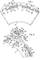
- Fig. 1 is a fragmentary side elevational view of a brake disc assembly with a key slot and insert secured to the respective peripheral slots by clips.
- Fig. 2 is an exploded perspective view of the insert and clip in relation to a perspective view of a fragmentary portion of a rotor brake disc.
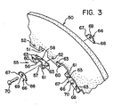
- Fig. 3 is an exploded perspective view of the insert and cap in relation to a perspective view of a fragmentary portion of a stationary brake disc.
- Referring to the drawings, wherein like reference numerals designate like or corresponding parts throughout the several views, there is shown in Fig. 1 a
friction brake disc 10 in the form of a rotor of a multiple disc aircraft brake. Although only a portion of one rotor disc is shown, it is understood that multiple discs refers to the plurality of axially spaced-apart annular rotor discs which are suitably splined for axial movement along a mating key or spline that is part of the rotating wheel. The plurality of annular rotors are interleaved with annular stator discs which in turn are suitably splined for axial movement along a mating key member (or members) that is fixedly secured to a torque tube not shown.Disc 10 is an annular member having flat annular wall surfaces with an inner and an outer periphery. As seen in Figs. 1 and 2,disc 10 has a plurality of circumferentially spacedslots 12 along itsouter periphery 13. - The
disc 10 is fabricated from a carbon material such as bulk graphite or carbon fabric composite. Thediscs 10 can be molded from chopped fibers of cellulose or other carbonizable materials and bonded or densified by a CVD process or by a resin later also to be carbonized, or can be molded from powders of graphite (or other forms of carbon) and densified by CVD process or by a carbonizable resin. The processing is done in a protective atmosphere. The disc l0.can be made by laying up flat sheets of cellulosic material and bonded or densified by CVD process or by impregnating with a carbonizable resin and processed at elevated temperatures. The processes for making the carbon discs are well known in the art and therefore will not be described herein. - A torque device 14 (shown in phantom lines in Fig. 1) is located adjacent to the outer periphery of the discs 10 (only a portion of one shown in Fig. 1).
Torque device 14 has a plurality of splines, ribs ordisc engaging members 16 projecting intoslots 12 to provide a means for applying a load or force on thedisc 10 by its engagement withslot 12.Slot 12 has abottom surface 18, and two radially extendingplanar side walls - A metal insert 25 (Fig. 2) is located within each
slot 12 to provide a reinforcement means for driving contact from thesplines 16 oftorque device 14. Each insert has a generally U-shaped configuration, with a pair of end sections 26-27 which are adapted to engage theplanar side walls slot 12 such that the forces applied to the end sections 26-27 transfer the forces to theplanar side walls end sections bridging section 28. The bottom surface of thebridging section 28 is in abutting contact with thebottom surface 18 ofslot 12. Therespective end sections arms bridging section 28. Each of thearms shoulder 32 and anabutment 33. The pairs of arms 30-and 31 extend in opposite directions and are substantially parallel and lightly contact the outer peripheral annular surface ofdisc 10. - Each pair of
arms periphery 13 of the disc. The outer periphery ofdisc 10 contains a pair ofbores 35 to either side ofslot 12. Since the pairs ofarms insert 25 extend along theperiphery 13 of thedisc 10, the pairs ofbores 35 are located along the periphery but beyond the respective edges of thearms - The
inserts 25 are retained within their respective slots viaclips 36. Eachclip 36 is an elongated member with a recessed or reduced end defining anabutment 37 which forms a shoulder which can frictionally abutshoulder 32 ofinsert 25. By reducing the width ofclip 36adjacent abutment 37, arecess 38 is formed such as to receive theabutment 33 ofinsert 25, while theabutment 37 enters the notched upper outermost corner of theadjacent arms abutment 37 can frictionally abut theshoulder 32 of such arms. Eachclip 36 has a pair ofopenings 40 which are spaced the same distance as the pairs ofbores 35 along the periphery ofdisc 10. On aligning theopenings 40 withbores 35, theclips 36 can be rigidly secured to the periphery ofdisc 10 byrivets 41 extending through the respective openings and bores. - In multiple disc brakes, the
splines 16 oftorque device 14 extends into theslots 12 of the axially alignedrotor brake discs 10. Therespective slots 12 receive theinserts 25 such that therespective clips 36 to either side of anyinsert 25 will retain theinsert 25 within the slot since therespective abutments 37 of clip -36 overlie theabutment 33 ofinsert 25. Theshoulder 32 formed by the recess in tne arms 30-31 ofinsert 25 thus can abuttingly contact the surface or edge of theabutment 37 ofclip 36. This design permits theinsert 25 to float freely in theslot 12 of thecarbon disc 10 eliminating any tension thereon that otherwise would occur ifinsert 25 were firmly riveted to thedisc 10. By permitting the floating ofinsert 25, the respective planar surfaces of theend sections side walls slot 12 indisc 10. - Stator discs can also be provided with similar torque-transmitting inserts in a manner similar to those used in the
rotor disc 10 described above. Fig. 3 discloses part of an annular surface of astator brake disc 50 having a plurality ofslots 51 along the inner periphery thereof. The stator discs are suitably splined for axial movement along a mating key memoer that is fixedly secured to a stationary torque tube not shown.Slot 51 is similar toslot 12 ofdisc 10 in having a bottom surface and two oppositely disposed radially extending wall surfaces. Thestator disc 50 has a plurality of circumferentially spaced bores 52 located along the inner periphery preferably half way between therespective slots 51. - An
insert 55 identical to insert 25 described above is located within eachslot 51.Insert 55 has a U-shaped configuration with spaced legs or end sections 56-57, which sections are adapted to engage the planar side walls ofslot 51 such that the forces applied to the end sections 56-57 are transferred to their respective side walls thereof. Theena sections bridging section 58. As viewed in Fig. 3, the top surface of bridgingsection 58 is in contact with the bottom surface ofslot 51. Therespective end sections arms bridging section 58. Each of thearms abutment 63. - The pairs of
arms disc 50. Each pair ofarms disc 50. - The
inserts 55 are retained within theirrespective slots 51 via clips 66. Eachclip 66 is an elongated flat member with reduced ends defining a pair of square shapedabutments respective arms clip 66 has acentral bore 69 which when aligned with thebore 52 in the inner periphery ofdisc 50 can receive arivet 70 which fastens the clip to thedisc 50. In this fastened position ofclip 66, the pair ofabutments respective arms insert 55 within the slots. A single clip in this instance can engage and retain opposite portions of twoadjacent inserts 55 as seen in Fig. 3.Clips 66 are mounted on both sides of the flat annular surface of thediscs 50. - In the operation of the
discs splines 16 oftorque device 14 extends intoslots 12 of the axially alignedrotor brake discs 10. The axially alignedstators 50 interleaved between the annular axially aligned and axially spacedrotor discs 10 are suitably splined for axial movement along a mating key member that is fixedly secured to a stationary torque tube and is subject to being moved axially by suitable actuators such as a piston. When the brakes are applied, therotor discs 10 and thestator discs 50 are axially squeezed together. The frictional forces between the faces of the rotor discs and the stator discs creates a load at theslots splines 16 and the mating key members of thestationary brake discs 50. This load is transmitted to the sides or legs of the U-shaped inserts 25 and 55, which via their flat faces exert a force directly on the appropriate walls ofslots inserts - Various modifications are contemplated and may obviously be resorted to by those skilled in the art without departing from the described inventions as hereinafter defined by the appended claims, as only a preferred embodiment thereof has been defined.
Claims (6)
Applications Claiming Priority (2)
| Application Number | Priority Date | Filing Date | Title |
|---|---|---|---|
| US461818 | 1983-01-28 | ||
| US06/461,818 US4469204A (en) | 1983-01-28 | 1983-01-28 | Brake apparatus |
Publications (2)
| Publication Number | Publication Date |
|---|---|
| EP0115280A1 true EP0115280A1 (en) | 1984-08-08 |
| EP0115280B1 EP0115280B1 (en) | 1987-11-19 |
Family
ID=23834043
Family Applications (1)
| Application Number | Title | Priority Date | Filing Date |
|---|---|---|---|
| EP84100241A Expired EP0115280B1 (en) | 1983-01-28 | 1984-01-11 | Brake apparatus |
Country Status (7)
| Country | Link |
|---|---|
| US (1) | US4469204A (en) |
| EP (1) | EP0115280B1 (en) |
| JP (1) | JPS59144832A (en) |
| CA (1) | CA1211055A (en) |
| DE (1) | DE3467606D1 (en) |
| ES (1) | ES529169A0 (en) |
| IL (1) | IL70619A (en) |
Cited By (3)
| Publication number | Priority date | Publication date | Assignee | Title |
|---|---|---|---|---|
| WO1989005924A1 (en) * | 1987-12-18 | 1989-06-29 | Allied-Signal Inc. | Dual disk brake |
| WO2007026123A1 (en) | 2005-09-03 | 2007-03-08 | Riwa Limited | A pest monitoring system |
| EP3168492A3 (en) * | 2015-11-11 | 2017-06-14 | Goodrich Corporation | Low radial profile brake disk insert retainer |
Families Citing this family (10)
| Publication number | Priority date | Publication date | Assignee | Title |
|---|---|---|---|---|
| US4863001A (en) * | 1987-02-18 | 1989-09-05 | The Bf Goodrich Company | Brake apparatus |
| US4784246A (en) * | 1987-02-18 | 1988-11-15 | The B. F. Goodrich Company | Brake apparatus |
| US5273140A (en) * | 1992-09-25 | 1993-12-28 | Allied-Signal Inc. | Brake disc annular drive insert |
| US7168528B1 (en) | 1999-05-11 | 2007-01-30 | Goodrich Corporation | Three run disk brake stack and method of assembly |
| US6340075B1 (en) | 1999-11-24 | 2002-01-22 | The B. F. Goodrich Company | Three run disk brake stack and method of assembly |
| DE60105206T2 (en) * | 2001-06-13 | 2005-09-08 | Freni Brembo S.P.A. | WASHER OF COMPOSITE MATERIAL FOR A DISC BRAKE |
| US7442443B2 (en) | 2005-05-31 | 2008-10-28 | Goodrich Corporation | Chromium-nickel stainless steel alloy article having oxide coating formed from the base metal suitable for brake apparatus |
| US20070175709A1 (en) * | 2006-01-31 | 2007-08-02 | Honeywell International Inc. | Low friction stator insert assembly |
| US20080041674A1 (en) * | 2006-08-18 | 2008-02-21 | Honeywell International Inc. | Carbon-carbon stator insert for aircraft brakes |
| US9976612B2 (en) * | 2015-11-11 | 2018-05-22 | Goodrich Corporation | Single fastener brake disk insert retainer |
Citations (6)
| Publication number | Priority date | Publication date | Assignee | Title |
|---|---|---|---|---|
| FR2043008A5 (en) * | 1969-04-07 | 1971-02-12 | Goodrich Co B F | |
| GB1426416A (en) * | 1974-01-16 | 1976-02-25 | Goodyear Tire & Rubber | Low wear disc brake assembly |
| DE2634165A1 (en) * | 1975-09-29 | 1977-04-07 | Bendix Corp | CARBON FRICTION DISC |
| DE2705157A1 (en) * | 1976-02-05 | 1977-08-11 | Goodyear Aerospace Corp | BRAKE DISC |
| DE2944793A1 (en) * | 1978-11-06 | 1980-05-14 | Bendix Corp | CARBON FRICTION DISC |
| DE1933040B2 (en) * | 1968-06-25 | 1981-04-30 | The Goodyear Tire & Rubber Co., 44316 Akron, Ohio | Brake disc |
Family Cites Families (3)
| Publication number | Priority date | Publication date | Assignee | Title |
|---|---|---|---|---|
| GB1446554A (en) * | 1972-12-20 | 1976-08-18 | Dunlop L D | Friction discs |
| US4083434A (en) * | 1976-04-26 | 1978-04-11 | Pinter Henry J | Brake disc with anti-oxidation peripheral covering |
| AU4995179A (en) * | 1978-09-25 | 1980-04-03 | B.F. Goodrich Company, The | Disc brake assembly containing split discs |
-
1983
- 1983-01-28 US US06/461,818 patent/US4469204A/en not_active Expired - Lifetime
-
1984
- 1984-01-05 IL IL70619A patent/IL70619A/en unknown
- 1984-01-10 CA CA000444977A patent/CA1211055A/en not_active Expired
- 1984-01-11 EP EP84100241A patent/EP0115280B1/en not_active Expired
- 1984-01-11 DE DE8484100241T patent/DE3467606D1/en not_active Expired
- 1984-01-24 JP JP59009604A patent/JPS59144832A/en active Granted
- 1984-01-26 ES ES529169A patent/ES529169A0/en active Granted
Patent Citations (6)
| Publication number | Priority date | Publication date | Assignee | Title |
|---|---|---|---|---|
| DE1933040B2 (en) * | 1968-06-25 | 1981-04-30 | The Goodyear Tire & Rubber Co., 44316 Akron, Ohio | Brake disc |
| FR2043008A5 (en) * | 1969-04-07 | 1971-02-12 | Goodrich Co B F | |
| GB1426416A (en) * | 1974-01-16 | 1976-02-25 | Goodyear Tire & Rubber | Low wear disc brake assembly |
| DE2634165A1 (en) * | 1975-09-29 | 1977-04-07 | Bendix Corp | CARBON FRICTION DISC |
| DE2705157A1 (en) * | 1976-02-05 | 1977-08-11 | Goodyear Aerospace Corp | BRAKE DISC |
| DE2944793A1 (en) * | 1978-11-06 | 1980-05-14 | Bendix Corp | CARBON FRICTION DISC |
Cited By (4)
| Publication number | Priority date | Publication date | Assignee | Title |
|---|---|---|---|---|
| WO1989005924A1 (en) * | 1987-12-18 | 1989-06-29 | Allied-Signal Inc. | Dual disk brake |
| WO2007026123A1 (en) | 2005-09-03 | 2007-03-08 | Riwa Limited | A pest monitoring system |
| EP3168492A3 (en) * | 2015-11-11 | 2017-06-14 | Goodrich Corporation | Low radial profile brake disk insert retainer |
| US9897153B2 (en) | 2015-11-11 | 2018-02-20 | Goodrich Corporation | Low radial profile brake disk insert retainer |
Also Published As
| Publication number | Publication date |
|---|---|
| DE3467606D1 (en) | 1987-12-23 |
| ES8505773A1 (en) | 1985-06-01 |
| ES529169A0 (en) | 1985-06-01 |
| EP0115280B1 (en) | 1987-11-19 |
| US4469204A (en) | 1984-09-04 |
| JPH0356330B2 (en) | 1991-08-28 |
| IL70619A (en) | 1988-06-30 |
| CA1211055A (en) | 1986-09-09 |
| JPS59144832A (en) | 1984-08-20 |
| IL70619A0 (en) | 1984-04-30 |
Similar Documents
| Publication | Publication Date | Title |
|---|---|---|
| US4511021A (en) | Brake apparatus | |
| US4465165A (en) | Brake apparatus | |
| US4469204A (en) | Brake apparatus | |
| CN108533649B (en) | Carbon-carbon composite disc brake assembly | |
| US4585096A (en) | Brake apparatus | |
| US5299667A (en) | Carbon composite laminated structure | |
| US3936552A (en) | Nonmetallic composite friction member | |
| US5558186A (en) | Friction disk with renewable wear faces | |
| US4878563A (en) | Brake apparatus | |
| EP1826447B1 (en) | Method and brake disc with composite insert member | |
| CA1282349C (en) | Segmented friction brake or clutch disc assembly | |
| US5024297A (en) | Torque transmitting beam for wheel having brake torque drives | |
| US4557356A (en) | Brake disk and keyslot reinforcements therefor | |
| EP1988305B1 (en) | Load-distributing rotor insert for aircraft brakes | |
| US3724613A (en) | Brake disc with beryllium core and carbon wear faces | |
| US3425524A (en) | Brake disc structure | |
| US4967893A (en) | Friction assembly | |
| US6205633B1 (en) | Methods of converting aircraft brake assemblies | |
| US3904000A (en) | Segmented brake disk | |
| US20100014913A1 (en) | Reinforced Splines and their Manufacture | |
| US5769185A (en) | Carbon brake disc structures and method of making same | |
| US5730259A (en) | Method of producing wet frictional plate | |
| DE2042097A1 (en) | Friction member consisting of segments for brakes or clutches | |
| US3747712A (en) | Friction disc for disc brake | |
| US3807534A (en) | Friction disc |
Legal Events
| Date | Code | Title | Description |
|---|---|---|---|
| PUAI | Public reference made under article 153(3) epc to a published international application that has entered the european phase |
Free format text: ORIGINAL CODE: 0009012 |
|
| AK | Designated contracting states |
Designated state(s): DE FR GB IT |
|
| 17P | Request for examination filed |
Effective date: 19850122 |
|
| 17Q | First examination report despatched |
Effective date: 19860401 |
|
| GRAA | (expected) grant |
Free format text: ORIGINAL CODE: 0009210 |
|
| AK | Designated contracting states |
Kind code of ref document: B1 Designated state(s): DE FR GB IT |
|
| PG25 | Lapsed in a contracting state [announced via postgrant information from national office to epo] |
Ref country code: IT Free format text: LAPSE BECAUSE OF FAILURE TO SUBMIT A TRANSLATION OF THE DESCRIPTION OR TO PAY THE FEE WITHIN THE PRESCRIBED TIME-LIMIT;WARNING: LAPSES OF ITALIAN PATENTS WITH EFFECTIVE DATE BEFORE 2007 MAY HAVE OCCURRED AT ANY TIME BEFORE 2007. THE CORRECT EFFECTIVE DATE MAY BE DIFFERENT FROM THE ONE RECORDED. Effective date: 19871119 |
|
| REF | Corresponds to: |
Ref document number: 3467606 Country of ref document: DE Date of ref document: 19871223 |
|
| ET | Fr: translation filed | ||
| PLBE | No opposition filed within time limit |
Free format text: ORIGINAL CODE: 0009261 |
|
| STAA | Information on the status of an ep patent application or granted ep patent |
Free format text: STATUS: NO OPPOSITION FILED WITHIN TIME LIMIT |
|
| 26N | No opposition filed | ||
| ITTA | It: last paid annual fee | ||
| PGFP | Annual fee paid to national office [announced via postgrant information from national office to epo] |
Ref country code: DE Payment date: 19931220 Year of fee payment: 11 |
|
| PG25 | Lapsed in a contracting state [announced via postgrant information from national office to epo] |
Ref country code: DE Effective date: 19951003 |
|
| PGFP | Annual fee paid to national office [announced via postgrant information from national office to epo] |
Ref country code: GB Payment date: 20001220 Year of fee payment: 18 Ref country code: FR Payment date: 20001220 Year of fee payment: 18 |
|
| REG | Reference to a national code |
Ref country code: GB Ref legal event code: IF02 |
|
| PG25 | Lapsed in a contracting state [announced via postgrant information from national office to epo] |
Ref country code: GB Free format text: LAPSE BECAUSE OF NON-PAYMENT OF DUE FEES Effective date: 20020111 |
|
| GBPC | Gb: european patent ceased through non-payment of renewal fee |
Effective date: 20020111 |
|
| PG25 | Lapsed in a contracting state [announced via postgrant information from national office to epo] |
Ref country code: FR Free format text: LAPSE BECAUSE OF NON-PAYMENT OF DUE FEES Effective date: 20020930 |
|
| REG | Reference to a national code |
Ref country code: FR Ref legal event code: ST |