EP0115116B1 - Diagnostic device for colour sorting apparatus - Google Patents
Diagnostic device for colour sorting apparatus Download PDFInfo
- Publication number
- EP0115116B1 EP0115116B1 EP83305405A EP83305405A EP0115116B1 EP 0115116 B1 EP0115116 B1 EP 0115116B1 EP 83305405 A EP83305405 A EP 83305405A EP 83305405 A EP83305405 A EP 83305405A EP 0115116 B1 EP0115116 B1 EP 0115116B1
- Authority
- EP
- European Patent Office
- Prior art keywords
- sorting
- circuit means
- malfunctioning
- signals
- diagnostic device
- Prior art date
- Legal status (The legal status is an assumption and is not a legal conclusion. Google has not performed a legal analysis and makes no representation as to the accuracy of the status listed.)
- Expired
Links
- 230000007257 malfunction Effects 0.000 claims description 5
- 235000013339 cereals Nutrition 0.000 description 20
- 235000021251 pulses Nutrition 0.000 description 5
- 230000000694 effects Effects 0.000 description 2
- 244000105624 Arachis hypogaea Species 0.000 description 1
- 244000068988 Glycine max Species 0.000 description 1
- 235000010469 Glycine max Nutrition 0.000 description 1
- 240000007594 Oryza sativa Species 0.000 description 1
- 235000007164 Oryza sativa Nutrition 0.000 description 1
- 235000021307 Triticum Nutrition 0.000 description 1
- 244000098338 Triticum aestivum Species 0.000 description 1
- 235000011453 Vigna umbellata Nutrition 0.000 description 1
- 240000001417 Vigna umbellata Species 0.000 description 1
- 238000007664 blowing Methods 0.000 description 1
- 230000003111 delayed effect Effects 0.000 description 1
- 238000001514 detection method Methods 0.000 description 1
- 230000002542 deteriorative effect Effects 0.000 description 1
- 238000010586 diagram Methods 0.000 description 1
- 235000020232 peanut Nutrition 0.000 description 1
- 235000009566 rice Nutrition 0.000 description 1
- 230000001360 synchronised effect Effects 0.000 description 1
- 230000000007 visual effect Effects 0.000 description 1
Images
Classifications
-
- B—PERFORMING OPERATIONS; TRANSPORTING
- B07—SEPARATING SOLIDS FROM SOLIDS; SORTING
- B07C—POSTAL SORTING; SORTING INDIVIDUAL ARTICLES, OR BULK MATERIAL FIT TO BE SORTED PIECE-MEAL, e.g. BY PICKING
- B07C5/00—Sorting according to a characteristic or feature of the articles or material being sorted, e.g. by control effected by devices which detect or measure such characteristic or feature; Sorting by manually actuated devices, e.g. switches
- B07C5/34—Sorting according to other particular properties
- B07C5/342—Sorting according to other particular properties according to optical properties, e.g. colour
-
- G—PHYSICS
- G07—CHECKING-DEVICES
- G07C—TIME OR ATTENDANCE REGISTERS; REGISTERING OR INDICATING THE WORKING OF MACHINES; GENERATING RANDOM NUMBERS; VOTING OR LOTTERY APPARATUS; ARRANGEMENTS, SYSTEMS OR APPARATUS FOR CHECKING NOT PROVIDED FOR ELSEWHERE
- G07C3/00—Registering or indicating the condition or the working of machines or other apparatus, other than vehicles
-
- B—PERFORMING OPERATIONS; TRANSPORTING
- B07—SEPARATING SOLIDS FROM SOLIDS; SORTING
- B07C—POSTAL SORTING; SORTING INDIVIDUAL ARTICLES, OR BULK MATERIAL FIT TO BE SORTED PIECE-MEAL, e.g. BY PICKING
- B07C5/00—Sorting according to a characteristic or feature of the articles or material being sorted, e.g. by control effected by devices which detect or measure such characteristic or feature; Sorting by manually actuated devices, e.g. switches
- B07C5/34—Sorting according to other particular properties
- B07C5/342—Sorting according to other particular properties according to optical properties, e.g. colour
- B07C5/3425—Sorting according to other particular properties according to optical properties, e.g. colour of granular material, e.g. ore particles, grain
-
- B—PERFORMING OPERATIONS; TRANSPORTING
- B07—SEPARATING SOLIDS FROM SOLIDS; SORTING
- B07C—POSTAL SORTING; SORTING INDIVIDUAL ARTICLES, OR BULK MATERIAL FIT TO BE SORTED PIECE-MEAL, e.g. BY PICKING
- B07C5/00—Sorting according to a characteristic or feature of the articles or material being sorted, e.g. by control effected by devices which detect or measure such characteristic or feature; Sorting by manually actuated devices, e.g. switches
- B07C5/36—Sorting apparatus characterised by the means used for distribution
- B07C5/363—Sorting apparatus characterised by the means used for distribution by means of air
- B07C5/365—Sorting apparatus characterised by the means used for distribution by means of air using a single separation means
Definitions
- the present invention relates to a diagnostic device for use in a colour sorting apparatus.
- Another object of the present invention is to provide a diagnostic device for use in a colour sorting apparatus which is capable of controlling the feeders so that the feeding of grains to the malfunctioning sorting channel is interrupted thus contributing to the promotion of a better sorting performance of the apparatus.
- a diagnostic device for use in a colour sorting apparatus having a plurality of sorting channels, the device comprising: a scanner circuit means having a plurality of switching circuits respectively connected to a plurality of measuring points in each of the sorting channels, the switching circuits being operable to select one after another a particular sorting channel to be measured among the sorting channels; a comparator circuit means for comparing output signals measured at the respective measuring points within the selected sorting channel with reference signals preset for the respective measuring points; and an alarm means for indicating the malfunctioning portion of the selected sorting channel which is out of order upon receipt of the signals from the scanner circuit means and the comparator circuit means, whereby the malfunctioning sorting channel and the malfunctioning portion therein are indicated by the alarm means if there is a discrepancy between the reference signals and the output signals when compared by the comparator circuit means.
- the present invention also provides a diagnostic device which further comprises a feeder control means for controlling the operation of feeders respectively arranged for the sorting channels upon receipt of the signals from the scanner circuit means and the comparator circuit means, whereby the malfunctioning sorting channel and the malfunctioning portion therein are indicated by the alarm means and the feeding of grains to the malfunctioning sorting channel is interrupted if there is a discrepancy between the reference signals and the output signals when compared by the comparator circuit means.
- the references Q1 ⁇ Qn represent respective sorting channels disposed within the colour sorting apparatus.
- These respective sorting channels Q1 ⁇ Qn comprise: light sensitive sensors S1 ⁇ Sn for detecting the amount of light from the reference background and the amount of reflected and/or transmitted light from the grains flowing so as to be sorted; pre-amplifiers A1An for amplifying the outputs fed from the sensors S1-Sn; main amplifiers B1-Bn; and comparators C1 ⁇ Cn for comparing the outputs sent from the main amplifiers B1 ⁇ Bn with the reference outputs set-up by means of level setters K1 ⁇ Kn and producing outputs at the passage of a grain of a colour different from the colour (hereinafter referred to as a substandard grain).
- Output signals from the comparators C1 ⁇ Cn are delayed by signal delay circuits D1 ⁇ Dn and driver circuits E1-En are activated so as to actuate electromagnetic valves F1 ⁇ Fn of an ejector, thereby blowing off the substandard grain with compressed air from the ejector when the substandard grain passes in front of the ejector.
- the outputs of the scanner circuit means are applied to a comparator circuit means which includes amplifiers Ma-Md, wave processing circuits Wa-Wd, comparators Ha-Hd, reference waveform generator circuits W'a-W'd and an OR gate G.
- a comparator circuit means which includes amplifiers Ma-Md, wave processing circuits Wa-Wd, comparators Ha-Hd, reference waveform generator circuits W'a-W'd and an OR gate G.
- the outputs of the comparators Ha-Hd are input to the OR gate G and the output of this OR gate G is in turn applied to a feeder control means, that is, the above switching circuit 7. Outputs of this switching circuit 7 are respectively connected to feeders X1 ⁇ Xn which are means for feeding or stopping the grains to the respective sorting channels.
- the outputs of the comparators Ha-Hd are also applied to a display device 8 which is arranged also to receive an output signal from the abovementioned scanner driven circuit 2 and which is further connected to an alarm device 9 such as a buzzer or bell.
- An alarm means may be formed by the display device 8 alone or together with the alarm device 9.
- each of the sensors S1-Sn for the respective sorting channels 01-Qn detects the colour of the grains flowing down the respective channels and sends out a certain detection signal.
- the scanner driver circuit 2 operates upon receipt of the pulse signals from the pulse generator circuit 1 to drive the respective a-, b-, c-, d-point switching circuits 3, 4, 5, 6 and the switching circuit 7 so as to switch their respective contacts in succession from 1 to n stationary contacts in a synchronous manner.
- the stationary contacts "2" in the respective switching circuits are selected by the scanner driver circuit 2.
- the respective measuring points a2, b2, c2, d2, within the sorting channel Q2 are electrically connected through the respective a-, b-, c-, d-point switching circuits 3, 4, 5, 6 to the amplifiers Ma-Md where the output signals measured at the respective measuring points a2, b2, c2, d2 are amplified.
- the signals being amplified at the amplifiers Ma-Md are then passed to the wave processing circuits Wa-Wd where they are wave-processed so as to be made applicable for the comparison operation, and in turn passed to the comparators Ha-Hd where the processed signals are compared with the reference signals produced by means of the reference waveform generator circuits W'a-W'd.
- the display device 8 receives the output signals from the comparators Ha-Hd and is arranged to operate to indicate each sorting channel number synchronously with the stationary contacts of the respective switching circuits 3-7 by the scanner driver circuit 2. Thus, supposing that the comparator Hb sends out an output signal, the display device 8 operates to indicate the number, which in this case is number "2", representing the present number of the particular sorting channel undergoing measuring operation which has been selected by the respective switching circuits 3 ⁇ 6, and also the display device 8 operates to indicate the character "b", based upon the output signal from the comparator Hb, representing the measuring point where any malfunction has occurred. As a result, there will be an indication of "2-b" showing that there is a malfunction at the b-point within the sorting channel Q2. In addition to this visual indication, the alarm device 9 of bells or the like operates to give warning of an occurrence of any malfunction in an audible manner.
- measuring points there are arranged four measuring points per sorting channel within the apparatus, but five or six or more measuring points may well be arranged if desired. The increase in measuring points will ensure circumstantial discovery of malfunctioning portions.
- the first advantageous effect offered by the present invention is that when any portion withing the sorting channel is out of order within the colour sorting apparatus having a large number of sorting channels, the malfunctioning sorting channel and the malfunctioning portion therein are indicated on the display device so that any malfunctioning parts can be quickly discovered and repaired.
- the second advantageous effect in addition to the one given above, is that since the feeding of grains to the sorting channel out of order can be timely stopped, there is less possibility of substandard grains being mixed in the acceptable grains and this contributes to the promotion of better sorting performance, and also the fact that the malfunctioning sorting channel can be quickly restored means the improvement of overall sorting efficiency of the colour sorting apparatus.
Landscapes
- Physics & Mathematics (AREA)
- General Physics & Mathematics (AREA)
- Sorting Of Articles (AREA)
- Investigating Materials By The Use Of Optical Means Adapted For Particular Applications (AREA)
- Alarm Systems (AREA)
Description
- The present invention relates to a diagnostic device for use in a colour sorting apparatus.
- A colour sorting apparatus is used for automatically separating grains with a colour different from a reference colour from grains to be sorted such as rice grains, wheat, red beans, soy beans, and peanuts. In such colour sorting apparatus, it is necessary to provide a large number of sorting channels because only one grain at a time is subjected to the sorting operation and therefore there are usually provided 20 to 30 sorting channels. A colour sorting apparatus of the kind to which the diagnostic device according to the present invention may be applied and which has a large number of sorting channels is found in, for example, the United States Patent No. 3,738,484. With a colour sorting apparatus of this kind, if there occurs any malfunction even in only one of those sorting channels, this causes unacceptable grains to be mixed in the acceptable grains which have been sorted, thereby seriously deteriorating the sorting performance of the apparatus.
- Accordingly, it is a primary object of the present invention to provide a diagnostic device for use in a colour sorting apparatus which is capable of detecting from among a large number of sorting channels a particular sorting channel which is out of order.
- Another object of the present invention is to provide a diagnostic device for use in a colour sorting apparatus which is capable of controlling the feeders so that the feeding of grains to the malfunctioning sorting channel is interrupted thus contributing to the promotion of a better sorting performance of the apparatus.
- In accordance with the present invention, there is provided a diagnostic device for use in a colour sorting apparatus having a plurality of sorting channels, the device comprising: a scanner circuit means having a plurality of switching circuits respectively connected to a plurality of measuring points in each of the sorting channels, the switching circuits being operable to select one after another a particular sorting channel to be measured among the sorting channels; a comparator circuit means for comparing output signals measured at the respective measuring points within the selected sorting channel with reference signals preset for the respective measuring points; and an alarm means for indicating the malfunctioning portion of the selected sorting channel which is out of order upon receipt of the signals from the scanner circuit means and the comparator circuit means, whereby the malfunctioning sorting channel and the malfunctioning portion therein are indicated by the alarm means if there is a discrepancy between the reference signals and the output signals when compared by the comparator circuit means.
- The present invention also provides a diagnostic device which further comprises a feeder control means for controlling the operation of feeders respectively arranged for the sorting channels upon receipt of the signals from the scanner circuit means and the comparator circuit means, whereby the malfunctioning sorting channel and the malfunctioning portion therein are indicated by the alarm means and the feeding of grains to the malfunctioning sorting channel is interrupted if there is a discrepancy between the reference signals and the output signals when compared by the comparator circuit means.
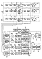
- One way of carrying out the invention is described in detail below with reference to the drawing which illustrates only one specific embodiment, in which a single Figure shows a block diagram of one preferred embodiment in accordance with the present invention.
- In the drawing, the references Q1―Qn represent respective sorting channels disposed within the colour sorting apparatus. These respective sorting channels Q1―Qn comprise: light sensitive sensors S1―Sn for detecting the amount of light from the reference background and the amount of reflected and/or transmitted light from the grains flowing so as to be sorted; pre-amplifiers A1An for amplifying the outputs fed from the sensors S1-Sn; main amplifiers B1-Bn; and comparators C1―Cn for comparing the outputs sent from the main amplifiers B1―Bn with the reference outputs set-up by means of level setters K1―Kn and producing outputs at the passage of a grain of a colour different from the colour (hereinafter referred to as a substandard grain). Output signals from the comparators C1―Cn are delayed by signal delay circuits D1―Dn and driver circuits E1-En are activated so as to actuate electromagnetic valves F1―Fn of an ejector, thereby blowing off the substandard grain with compressed air from the ejector when the substandard grain passes in front of the ejector. Measuring points a1―an which are output points of the pre-amplifiers A1-An, measuring points b1―bn which are output points of the main amplifiers B1-Bn, measuring points c1-cn which are output points of the comparators C1―Cn and measuring points d1―dn which are collector terminals of the transistors adapted to activate the electromagnetic valves F1―Fn of the ejector are respectively connected to a-point
switching circuit 3, b-point switching circuit 4, c-point switching circuit 5 and d-point switching circuit 6 of a scanner circuit means which includes a pulse generator circuit 1, ascanner driver circuit 2 and these a-, b-, c-, d-point switching circuits point switching circuits scanner driver circuit 2 which is adapted to be operable in response to the pulses fed from the pulse generator circuit 1. - The outputs of the scanner circuit means are applied to a comparator circuit means which includes amplifiers Ma-Md, wave processing circuits Wa-Wd, comparators Ha-Hd, reference waveform generator circuits W'a-W'd and an OR gate G. Thus, the respective outputs of the a-, b-, c-, and d-
point switching circuits circuit 2 and which is further connected to an alarm device 9 such as a buzzer or bell. An alarm means may be formed by the display device 8 alone or together with the alarm device 9. - Next, the operation of the diagnostic device for the colour sorting apparatus embodying the present invention will be explained below.
- Let us suppose that the colour sorting apparatus is now in an operating state and that grains to be sorted are flowing down in each of the sorting channels 01-Qn. Under this condition, each of the sensors S1-Sn for the respective sorting channels 01-Qn detects the colour of the grains flowing down the respective channels and sends out a certain detection signal. On the other hand, the
scanner driver circuit 2 operates upon receipt of the pulse signals from the pulse generator circuit 1 to drive the respective a-, b-, c-, d-point switching circuits scanner driver circuit 2. The respective measuring points a2, b2, c2, d2, within the sorting channel Q2 are electrically connected through the respective a-, b-, c-, d-point switching circuits - The display device 8 receives the output signals from the comparators Ha-Hd and is arranged to operate to indicate each sorting channel number synchronously with the stationary contacts of the respective switching circuits 3-7 by the
scanner driver circuit 2. Thus, supposing that the comparator Hb sends out an output signal, the display device 8 operates to indicate the number, which in this case is number "2", representing the present number of the particular sorting channel undergoing measuring operation which has been selected by therespective switching circuits 3―6, and also the display device 8 operates to indicate the character "b", based upon the output signal from the comparator Hb, representing the measuring point where any malfunction has occurred. As a result, there will be an indication of "2-b" showing that there is a malfunction at the b-point within the sorting channel Q2. In addition to this visual indication, the alarm device 9 of bells or the like operates to give warning of an occurrence of any malfunction in an audible manner. - In the above described embodiment, there are arranged four measuring points per sorting channel within the apparatus, but five or six or more measuring points may well be arranged if desired. The increase in measuring points will ensure circumstantial discovery of malfunctioning portions.
- As has been described hereinabove, the first advantageous effect offered by the present invention is that when any portion withing the sorting channel is out of order within the colour sorting apparatus having a large number of sorting channels, the malfunctioning sorting channel and the malfunctioning portion therein are indicated on the display device so that any malfunctioning parts can be quickly discovered and repaired.
- The second advantageous effect, in addition to the one given above, is that since the feeding of grains to the sorting channel out of order can be timely stopped, there is less possibility of substandard grains being mixed in the acceptable grains and this contributes to the promotion of better sorting performance, and also the fact that the malfunctioning sorting channel can be quickly restored means the improvement of overall sorting efficiency of the colour sorting apparatus.
- While the invention has been described in its preferred embodiment, it is to be distinctly understood that the invention is not limited thereto but may be otherwise variously embodied within the scope of the following claims.
Claims (4)
Applications Claiming Priority (2)
| Application Number | Priority Date | Filing Date | Title |
|---|---|---|---|
| JP57226500A JPS59117698A (en) | 1982-12-25 | 1982-12-25 | Trouble shooter for color selector |
| JP226500/82 | 1982-12-25 |
Publications (2)
| Publication Number | Publication Date |
|---|---|
| EP0115116A1 EP0115116A1 (en) | 1984-08-08 |
| EP0115116B1 true EP0115116B1 (en) | 1988-03-02 |
Family
ID=16846080
Family Applications (1)
| Application Number | Title | Priority Date | Filing Date |
|---|---|---|---|
| EP83305405A Expired EP0115116B1 (en) | 1982-12-25 | 1983-09-15 | Diagnostic device for colour sorting apparatus |
Country Status (8)
| Country | Link |
|---|---|
| US (1) | US4546885A (en) |
| EP (1) | EP0115116B1 (en) |
| JP (1) | JPS59117698A (en) |
| KR (1) | KR890000153B1 (en) |
| DE (1) | DE3375762D1 (en) |
| GB (1) | GB2132752B (en) |
| MY (1) | MY8700136A (en) |
| PH (1) | PH20248A (en) |
Families Citing this family (5)
| Publication number | Priority date | Publication date | Assignee | Title |
|---|---|---|---|---|
| US4774718A (en) * | 1987-07-24 | 1988-09-27 | Esm International Inc. | Automatic ejector rate normalizer |
| US5062532A (en) * | 1990-05-07 | 1991-11-05 | Esm International, Inc. | Sorting machine including photo site processing |
| US5150307A (en) * | 1990-10-15 | 1992-09-22 | Automation Industrial Control, Inc. | Computer-controlled system and method for sorting plastic items |
| JPH04186188A (en) * | 1990-11-21 | 1992-07-02 | Tokimec Inc | Monitoring device for ultrasonic converter |
| JPH05155433A (en) * | 1991-12-04 | 1993-06-22 | Daifuku Co Ltd | Sorting system |
Family Cites Families (12)
| Publication number | Priority date | Publication date | Assignee | Title |
|---|---|---|---|---|
| GB635756A (en) * | 1946-04-15 | 1950-04-19 | Sargrove Electronics Ltd | Improvements in and relating to continuous production processes |
| US3035232A (en) * | 1957-09-11 | 1962-05-15 | Westinghouse Air Brake Co | Voltage amplitude checking system |
| US3738484A (en) * | 1971-03-15 | 1973-06-12 | Mandrel Industries | Sorting machine |
| US3776381A (en) * | 1972-04-25 | 1973-12-04 | R Wood | Apparatus for sorting products |
| JPS557746B2 (en) * | 1972-08-26 | 1980-02-28 | ||
| JPS5025415U (en) * | 1973-06-28 | 1975-03-24 | ||
| US4107663A (en) * | 1974-03-26 | 1978-08-15 | Mitsubishi Denki Kabushiki Kaisha | Operation state display apparatus |
| US4088227A (en) * | 1976-07-12 | 1978-05-09 | Geosource Inc. | Multiplexed sorting apparatus with test circuitry |
| ZA786121B (en) * | 1978-10-31 | 1979-12-27 | Gunson Sa Ltd | Improvements relating to monitoring light sensitive electronic components |
| CA1126836A (en) * | 1978-12-25 | 1982-06-29 | Toshihiko Satake | Automatic control device for particle color discriminating apparatus |
| FR2461261A1 (en) * | 1979-07-11 | 1981-01-30 | Cit Alcatel | DEVICE FOR MONITORING THE CORRECT OPERATION OF ELECTRONIC EQUIPMENT |
| DE3174515D1 (en) * | 1981-01-19 | 1986-06-05 | Gunsons Sortex Ltd | Sorting machine |
-
1982
- 1982-12-25 JP JP57226500A patent/JPS59117698A/en active Granted
-
1983
- 1983-09-15 DE DE8383305405T patent/DE3375762D1/en not_active Expired
- 1983-09-15 GB GB08324787A patent/GB2132752B/en not_active Expired
- 1983-09-15 EP EP83305405A patent/EP0115116B1/en not_active Expired
- 1983-09-20 US US06/534,100 patent/US4546885A/en not_active Expired - Lifetime
- 1983-09-26 KR KR1019830004488A patent/KR890000153B1/en not_active Expired
- 1983-10-06 PH PH29663A patent/PH20248A/en unknown
-
1987
- 1987-12-30 MY MY136/87A patent/MY8700136A/en unknown
Also Published As
| Publication number | Publication date |
|---|---|
| US4546885A (en) | 1985-10-15 |
| DE3375762D1 (en) | 1988-04-07 |
| PH20248A (en) | 1986-10-10 |
| KR840007365A (en) | 1984-12-07 |
| GB2132752A (en) | 1984-07-11 |
| JPS59117698A (en) | 1984-07-07 |
| MY8700136A (en) | 1987-12-31 |
| GB8324787D0 (en) | 1983-10-19 |
| JPH0214759B2 (en) | 1990-04-09 |
| GB2132752B (en) | 1986-04-16 |
| KR890000153B1 (en) | 1989-03-08 |
| EP0115116A1 (en) | 1984-08-08 |
Similar Documents
| Publication | Publication Date | Title |
|---|---|---|
| WO2000037187A1 (en) | Event driven multicast material sorting system | |
| US4546885A (en) | Diagnostic device for color sorting apparatus | |
| EP0115122A1 (en) | Automatic background brightness control device for colour sorting apparatus | |
| US3171112A (en) | Fault indicator circuit for power supply system | |
| EP0399510A3 (en) | Sheet sorting method and apparatus | |
| US5048694A (en) | Apparatus for processing card-like articles | |
| US6296123B1 (en) | Bottle reject system | |
| US6510487B1 (en) | Design architecture for a parallel and serial programming interface | |
| JPH08146052A (en) | Overcurrent detection and control circuit of power supply device | |
| US3716123A (en) | Apparatus for sorting elongated articles | |
| US4523104A (en) | Switch debounce circuit | |
| JPH03238218A (en) | Article sorter | |
| US6255844B1 (en) | Semiconductor testing apparatus | |
| JPH0788441A (en) | Sorting device for bad flaw of resin and sorting method using the same | |
| US3244204A (en) | Multiple saw electronic control apparatus | |
| JPH09314068A (en) | Sorter and method therefor | |
| JPH08119491A (en) | Band shear line | |
| JPH0498949A (en) | Signal transmission system | |
| JPS60225681A (en) | Control apparatus for trouble of color sortor | |
| JPH0243510Y2 (en) | ||
| JPH073773U (en) | Sorting device with check circuit | |
| JPH0498950A (en) | Signal transmission system | |
| JPS621555B2 (en) | ||
| RU1787584C (en) | Device for controlling the process of sorting and accounting of items | |
| SU968773A1 (en) | Device for testing electric connections |
Legal Events
| Date | Code | Title | Description |
|---|---|---|---|
| PUAI | Public reference made under article 153(3) epc to a published international application that has entered the european phase |
Free format text: ORIGINAL CODE: 0009012 |
|
| AK | Designated contracting states |
Designated state(s): CH DE IT LI |
|
| 17P | Request for examination filed |
Effective date: 19841001 |
|
| 17Q | First examination report despatched |
Effective date: 19860603 |
|
| RAP1 | Party data changed (applicant data changed or rights of an application transferred) |
Owner name: SATAKE ENGINEERING CO., LTD. |
|
| GRAA | (expected) grant |
Free format text: ORIGINAL CODE: 0009210 |
|
| AK | Designated contracting states |
Kind code of ref document: B1 Designated state(s): CH DE IT LI |
|
| REF | Corresponds to: |
Ref document number: 3375762 Country of ref document: DE Date of ref document: 19880407 |
|
| ITF | It: translation for a ep patent filed | ||
| PLBE | No opposition filed within time limit |
Free format text: ORIGINAL CODE: 0009261 |
|
| STAA | Information on the status of an ep patent application or granted ep patent |
Free format text: STATUS: NO OPPOSITION FILED WITHIN TIME LIMIT |
|
| 26N | No opposition filed | ||
| ITTA | It: last paid annual fee | ||
| PGFP | Annual fee paid to national office [announced via postgrant information from national office to epo] |
Ref country code: CH Payment date: 20010914 Year of fee payment: 19 |
|
| PGFP | Annual fee paid to national office [announced via postgrant information from national office to epo] |
Ref country code: DE Payment date: 20011001 Year of fee payment: 19 |
|
| PG25 | Lapsed in a contracting state [announced via postgrant information from national office to epo] |
Ref country code: LI Free format text: LAPSE BECAUSE OF NON-PAYMENT OF DUE FEES Effective date: 20020930 Ref country code: CH Free format text: LAPSE BECAUSE OF NON-PAYMENT OF DUE FEES Effective date: 20020930 |
|
| PG25 | Lapsed in a contracting state [announced via postgrant information from national office to epo] |
Ref country code: DE Free format text: LAPSE BECAUSE OF NON-PAYMENT OF DUE FEES Effective date: 20030401 |
|
| REG | Reference to a national code |
Ref country code: CH Ref legal event code: PL |