EP0115097B1 - Generator of random number sequences - Google Patents
Generator of random number sequences Download PDFInfo
- Publication number
- EP0115097B1 EP0115097B1 EP83201780A EP83201780A EP0115097B1 EP 0115097 B1 EP0115097 B1 EP 0115097B1 EP 83201780 A EP83201780 A EP 83201780A EP 83201780 A EP83201780 A EP 83201780A EP 0115097 B1 EP0115097 B1 EP 0115097B1
- Authority
- EP
- European Patent Office
- Prior art keywords
- outputs
- registers
- generator
- coefficients
- logic
- Prior art date
- Legal status (The legal status is an assumption and is not a legal conclusion. Google has not performed a legal analysis and makes no representation as to the accuracy of the status listed.)
- Expired
Links
Images


Classifications
-
- G—PHYSICS
- G06—COMPUTING; CALCULATING OR COUNTING
- G06F—ELECTRIC DIGITAL DATA PROCESSING
- G06F7/00—Methods or arrangements for processing data by operating upon the order or content of the data handled
- G06F7/58—Random or pseudo-random number generators
- G06F7/582—Pseudo-random number generators
- G06F7/584—Pseudo-random number generators using finite field arithmetic, e.g. using a linear feedback shift register
-
- H—ELECTRICITY
- H04—ELECTRIC COMMUNICATION TECHNIQUE
- H04N—PICTORIAL COMMUNICATION, e.g. TELEVISION
- H04N7/00—Television systems
- H04N7/16—Analogue secrecy systems; Analogue subscription systems
- H04N7/167—Systems rendering the television signal unintelligible and subsequently intelligible
- H04N7/1675—Providing digital key or authorisation information for generation or regeneration of the scrambling sequence
-
- H—ELECTRICITY
- H04—ELECTRIC COMMUNICATION TECHNIQUE
- H04N—PICTORIAL COMMUNICATION, e.g. TELEVISION
- H04N7/00—Television systems
- H04N7/16—Analogue secrecy systems; Analogue subscription systems
- H04N7/167—Systems rendering the television signal unintelligible and subsequently intelligible
- H04N7/169—Systems operating in the time domain of the television signal
- H04N7/1696—Systems operating in the time domain of the television signal by changing or reversing the order of active picture signal portions
-
- G—PHYSICS
- G06—COMPUTING; CALCULATING OR COUNTING
- G06F—ELECTRIC DIGITAL DATA PROCESSING
- G06F2207/00—Indexing scheme relating to methods or arrangements for processing data by operating upon the order or content of the data handled
- G06F2207/58—Indexing scheme relating to groups G06F7/58 - G06F7/588
- G06F2207/581—Generating an LFSR sequence, e.g. an m-sequence; sequence may be generated without LFSR, e.g. using Galois Field arithmetic
-
- G—PHYSICS
- G06—COMPUTING; CALCULATING OR COUNTING
- G06F—ELECTRIC DIGITAL DATA PROCESSING
- G06F2207/00—Indexing scheme relating to methods or arrangements for processing data by operating upon the order or content of the data handled
- G06F2207/58—Indexing scheme relating to groups G06F7/58 - G06F7/588
- G06F2207/583—Serial finite field implementation, i.e. serial implementation of finite field arithmetic, generating one new bit or trit per step, e.g. using an LFSR or several independent LFSRs; also includes PRNGs with parallel operation between LFSR and outputs
Definitions
- the present invention relates to a pseudo-random digital sequence generator, applicable in particular to the encryption of television images.
- the principle of encrypting television images consists in cutting each image line at a point whose address is random, then in performing a circular permutation of the segments situated on either side of the cut point.
- This encryption principle has been described in patent application FR-A-2431809 filed on July 20, 1978 in the name of the Public Broadcasting Establishment known as "Telecommunicationdiffusion de France” if it applies to a black video signal. and white or composite color with frequency multiplexing, of the SECAM, PAL or NTSC type for example.
- Patent application EP-A-0103339 with priority of September 14, 1982 in the name of the company La Radiotechnique describes a new application of this principle to a color video signal with time multiplexing of analog components, of MAC type for example.
- the different components are treated separately, that is to say each one undergoes the cut-off and permutation operations separately.
- the addresses of cut-off points to be supplied must then be in a number equal to that of the components: two in the case of MAC coding (the luminance Y and, alternatively, one or the other of the color difference components U and V ), three in the case where the three components Y, U and V are transmitted to each line, etc.
- the addresses of the cut-off points are provided by a pseudo-random digital sequence generator operating with a clock at the line frequency and therefore vary pseudo-randomly from one line to the next.
- Identical generators are used for transmission and reception, and synchronization between transmission and reception can be done either with each frame of image, or after an integer number of frames (every 50 frames for example, it is i.e. every second in Europe), by providing a synchronization pulse transmitted by the transmitter in a special line of the image (the last line of a frame for example) or in the data transmission channel during frame returns (see systems called Teletext, DIDON, etc.).
- the generators used for transmission and reception are initialized by a starting key, comprising a certain number n d of bits, and the user can either buy this key directly in the form of a passive key card, or buy the means of decrypting an encrypted key transmitted by the transmitter in the data broadcasting channel.
- a starting key comprising a certain number n d of bits
- the latter solution allows as frequent a change of the key as is desired and therefore greater security of the system, but implies, on reception, the use of an active initialization circuit using a passive access card or active (memory or microprocessor based).
- a conventional pseudo-random digital sequence generator comprises, in its simplest version, a shift register with n stages numbered from 1 to n from the input to the output (see FIG. 1), comprising at least one intermediate output of rank k whose result of the addition modulo 2 with the output of rank n is re-entered at the input.
- the generator polynomial of this circuit is written: When this polynomial is irreducible and primitive, the generator delivers a pseudo-random sequence of maximum length equal to 2 "-1, which includes all the possible combinations of n bits with the exception of that composed of n consecutive zeros which would cause blocking of the system, which only delivers zeros.
- a particularly interesting version of such a circuit called the Geffe generator and described in particular in the article by EL Key, "An analysis of the structure and complexity of nonlinear binary sequence generators", published in the journal IEEE Transactions on Information Theory, volume IT-22, n ° 6, November 1976, pages 732 to 736, consists in using three registers A, B, C, using for example the output a of the first register to switch the output of the system to the output b of the second register, ie on the output c of the third.
- the application of a Geffe generator to the production of a pseudo-random address generator for encrypting television images also has an additional advantage in that a device comprising several simple generators is much more advantageous than 'a device with a single simple generator comprising the same total number n d of stages. Indeed, instead of having n d correlated outputs, there are three uncorrelated sets of outputs that can be combined with one another.
- the generator polynomials of the three registers A, B, C must be irreducible and primitive, so that the bit sequences a, b, c are of maximum lengths, that is to say equal respectively to 2 "a-1, 2" b- 1, 2 n c-1, these three lengths must also be prime to each other so that the length of a pseudo-random sequence, combination of bits a, b and c, being maximum and equal to product with a value of the order of magnitude of 2 " d .
- Geffe generators combining the different outputs of the same three registers A, B, C to generate the address bits of the cut-off points for the encryption of a television picture has, however, an important defect: because of the properties of the eye in terms of pattern recognition, and in particular its ability to identify an image whose probability of presence is greater than approximately 10%, we can, by successive approximations, decipher the device by first seeking by successive tests the (n b + n e ) bits corresponding to the initial loading word of the registers B and C, as has been demonstrated with the aid of an example in patent application FR-A-2538192 filed on 20 December 1982 and published on 06.22.84, on behalf of the company La Radiotechnique.
- a pseudo-random address generator using Geffe generators requires a number of key bits between 1.7 and 2 times greater than that which would be necessary in a device not using the principle of the Geffe generator and not allowing the recognition of the bits in two successive stages. For example, if it is estimated that an average time of the order of two hours is sufficient to discourage decryption attempts, this time can be obtained without a Geffe generator with a 14-bit key, whereas with a Geffe generator would require 26 bits if we choose lengths of registers A, B and C equal to 13, 7 and 6 respectively.
- a first object of the invention is therefore to propose a generator of pseudo-random digital sequences which can provide addresses of at least 4 bits with identical address probabilities of less than 10%, these addresses being at the same time much more difficult to decrypt. , when the key is not known, than those provided by the generators known up to now, and said generator simultaneously remedying the drawbacks of Geffe generators when these are applied to the encryption of television images.
- the invention relates to a pseudo-random digital address generator, intended in particular to supply cut-off point addresses of a composite video signal, in the case of a frequency multiplexing system of the SECAM, PAL or NTSC type. for example, or luminance and chrominance video signals in the case of a time multiplexing system of analog components of MAC type for example, with a view to carrying out an encryption of these video signals by circular permutation of the segments located on the one hand and other of each cut-off point, characterized in that it comprises three loopback shift registers, in that the generator polynomials of each of these registers are irreducible and primitive so that the bit sequences a, b, c qu 'they deliver are of maximum lengths, in that the numbers of cells n ⁇ , n b , ne of said registers are different, in that the three registers have several outputs ab j and c k , and in that the addresses of the cut-off points are constituted by sums of N terms of
- the Geffe generator has the same defect as the Geffe generator, in that it allows decryption by successive approximations. This is due to the fact that, as soon as 2 outputs of 2 generators (A and B, or B and C, or C and A) are identical, the result no longer depends on the output of the 3rd generator, as happened in the generator of Geffe when the outputs of generators B and C were identical. Consequently, the probability of decoding, i.e. the probability of identity of two independent outputs, is 3/4 per address bit, while it is only 1/2 when only a modulo 2 addition (a ⁇ b ⁇ c) is used, for example.
- a second object of the invention is to remedy this drawback by calculating the M most significant address bits successively from the values of the outputs a ,, b j , c k supplied at M different times of the clock. control of registers.
- the invention relates to a generator of pseudo-random digital sequences, intended in particular for supplying cut-off point addresses of a composite video signal, in the case of a frequency multiplexing system of SECAM, PAL or NTSC type by example, or addresses of cutoff points of the luminance and chrominance video signals in the case of a time multiplexing system of analog components of MAC type for example, with a view to carrying out an encryption of these video signals by changing the order of the points of the two segments located on either side of each cut-off point, this generator comprising three looping shift registers A, B and C whose cell numbers n a , n b and n c are different and whose generator polynomials are irreducible and primitive so that the bit sequences a, b, c that they deliver are of maximum lengths, the addresses of the cut points being deduced from the sum of N terms of weight 2 N- 1 to 2 ° and of respective coefficients S 0 to S N - 1 , characterized in
- the lengths (2 "a-1), (2 n b-1), (2 n c-1) of the sequences delivered by the three registers, which are maximum, can, here too, be chosen to be prime so that the length of the pseudo-random sequences formed by the combinations of bits a, b, c is itself maximum.
- the generator is therefore a Geffe generator with three shifted A, B, C shift registers, whose generator polynomials are irreducible and primitive, so that the bit sequences a, b, c which they deliver are of maximum lengths, that is to say equal respectively to 2 "a - 1, to 2 n b-1 and to 2 n c-1, n a , n b and n c therefore being the respective numbers of cells, or degrees, of the registers A, B and C, and being conventionally chosen in such a way that n a is greater than n b , itself greater than n c '
- the lengths of the three registers, which are maximum, here are chosen first among themselves, so that the length of the pseudo-random sequences formed by the combinations of bits a, b, c is itself maximum, and equal to the product (2 n a-1). (2 n b -1). (2 n c-1).
- the ranks i, j, k are chosen to be different, as much as the degrees n a , n b , n c allow it.
- the last coefficients of the address are either fixed, and chosen equal to 0 or 1, or deduced for one or more of them from outputs a, b j and c k using equations which do not include modulo 2 addition of three outputs.
- the modulo 2 addition can also be written, explaining the logical operations: These equations (5) or (5 bis) represent a linear system, and an attempt at decryption only requires the resolution of a number of linear equations equal to the number of bits n d of the key (n d being equal to n a + n b + n c ). To make this mathematical resolution more difficult, it is possible, in a second embodiment of the invention, to use, for the first most significant address bit, a logic equation containing for example two modulo 2 additions different, of type (a ⁇ b ⁇ c), the choice of which is dictated by the value of another bit a or b or c. When we choose n a greater than n b , itself greater than n c , this multiplier bit comes from the longest register A. To avoid using more than two outputs of the registers per address bit, we can use the same output has in both sums.
- the logical equation of the second highest weight coefficient S N - 2 is also of the type of equation (6) or (6 bis), with coefficients ijk chosen different, and the logical equations giving at least two of the following most significant coefficients are of the type of equation (7).
- the other coefficients are fixed and equal to 0 or 1.
- the two most significant coefficients S N - 1 and S N-2 each use two outputs from register A, two outputs from register B and two outputs from register C. If the length of the shortest register C n ' is for example that of 4, one will thus find, in the following address coefficients, outputs of C already used, which will increase the probability of address identity and, consequently, the risk of decryption by successive tests of keys.
- the logical equations giving at least two of the following most significant coefficients are of the type: by choosing different ijk ranks as much as the degrees of the registers allow, and the last coefficients are fixed and equal to 0 or 1.
- This system is however better protected against decryption by successive key tests, because it can be noted that the coefficient S N-1 always depends on b i , and that the coefficient S N - 2 always depends on C k " which allows reuse the outputs b j and C k " for the third or fourth coefficient S N - 3 or S N - 4 without reducing their efficiency.
- the protection is maximafe compared to a decryption in successive stages which would start with the bits of the shortest registers B and C.
- protection against decryption starting with the bits of registers A and B or registers A and C must also be sought.
- the generator previously described through four possible embodiments is capable of supplying 2 N different addresses of value 0 to 2 N-1 (we have indeed seen that any address of cut-off point was expressed by a sum S of N terms S h 2 h of weight 2 ° to 2 N-1 assigned respective coefficients S o to S N-1 ).
- S h 2 h of weight 2 ° to 2 N-1 assigned respective coefficients S o to S N-1 .
- the number of points stored in memory per line does not in practice exceed 990, taking into account the signal portion sacrificed to allow the repetition of an area in the vicinity of the cut-off point (redundancy characteristic, known from 'after the two patent applications already cited).
- N 10 or 1,024 possible addresses
- subject 2 P of these addresses between 2 N -2 P and 21-1, a decrease by an amount 2 ", p being chosen such that 2 N -2 P is less than M, and q being chosen equal to or greater than p but such that 2 q is less than 2 N -2 P.
- television signals stored always include an initial reference period containing either the black level when it is a black and white signal or a luminance signal, or a reference burst superimposed on the level black in the case of a PAL, SECAM or NTSC composite color signal, i.e. a reference level corresponding to level 0 of color difference in the case of a color difference signal U or V (case of MAC coding for example).
- this reference level could be identified relatively easily in the encrypted signal, it is important, to avoid decryption of the image, not to apply the permutation to this period, which amounts to prohibiting the cutoff addresses which fall within these reference periods.
- a simple way to achieve this prohibition is to subject the 2 r addresses provided by the generator, between 0 and 2 r -1, an increase of a quantity 2 1 , r being chosen so that 2 r is greater than the length L of the reference segment, and s being chosen equal to or greater than r but such that 2 1 is less than M-2 r .
- the length L does not exceed 100 sampled elements.
- This operation amounts to forcing the coefficient S 7 to the value 1 when the coefficients Sa and S 9 are both equal to 0, which can be obtained very simply by the circuit indicated in FIG. 5 which uses an OR gate and a non-OR gate with two inputs, checking the equation:
- this operation decreases the efficiency of the coefficient S 7 , which no longer has any influence on the address provided except during 3/4 of the time.
- the probability of address identity for 4 significant bits of address Se to S 9 therefore becomes equal, in the example cited and in the case where the smallest register has at least 4 cells, to:
- table 3 on page 21 indicates, according to the number of address bits, the address identity probabilities calculated in the case of the previous lower and upper bounds, for the first, second, third and fourth embodiment proposed, in the case where the lengths of the registers are respectively 4 for C, 5 for B and greater than or equal to 7 for A.
- the probability of decoding is equal to the minimum probability when we know the bits of B and C at the same time (9 bits).
- the probability of decoding is greater than the minimum probability, and does not drops below the perception threshold of 10% only when using at least four address bits in solution 1, five bits in solutions 2 and 4, and six bits in solution 3.
- the generator In the case of a time-division multiplex system of analog components, the generator must supply as many cut-off point addresses as there are components in each line, that is to say for example two in the case of the MAC system (where the components are Y and, alternatively, U and V).
- the luminance and chrominance components include information of similar forms, one does not lose in degree of secrecy by applying circular permutations analogous to these components, that is to say by calculating the two addresses from the same outputs of the same shift registers and using the same logic equations. This makes it possible to have an address generator whose complexity is practically no greater than in the previous case, only the problem of the terminals being able to differ according to the components.
- the coefficients of the luminance addresses are then chosen as follows: and It comes down to choosing which can be obtained very simply with a non-OR gate with two inputs as indicated in FIG. 6.
- This second solution has the advantage that the efficiency of the 6 coefficients A o to A 5 remains entire.
- the decoding probabilities are then those indicated in table 2 on page 17.
- the coefficients of the chrominance addresses would then be chosen as follows: and
- FIG. 7 constituted by the association of the parts of FIGS. 7a and 7b shows an example of practical embodiment of a generator of pseudo-random digital addresses adapted to the PAL, SECAM and NTSC signals.
- the lengths of the three registers A, B, C were chosen to be 11, 5 and 4 respectively, which allows approximately 950,000 different 20-bit keys.
- the irreducible and primitive generator polynomials, chosen to require only an intermediate tap on each register, are the following:
- the coefficients Se and S 7 are deduced from the outputs A s , A s , A 7 according to schemes programmed so that provides, in accordance with for example the fourth embodiment of the invention, an output A 7 according to equation (8 bis), an output A s according to equation (9 bis), and six outputs A o to A5 according to l 'equation (10).
- the following equations are chosen:
- the first two require 8 products, the following 4. We therefore use 40 products among the 48 available on the 82 S 100 network.
- the two address bits S 2 and S 3 deduced from A o and A 1 , correspond to translations that are too weak to make a significant contribution to interference as perceived by the eye. Their use however reinforces the costing vis-à-vis a mathematical decryption test; they make it more difficult to identify the jumps of addresses introduced by the coefficients S 4 to Sa since they introduce three possible additional addresses between each of the addresses supplied by S 4 to S 9 .
- This key is either supplied by a decoding card, or transmitted by the transmitter in encrypted form, then decrypted by an access circuit not shown.
- a new key arrives, it is transferred to a shift register D with 20 stages, in 20 strokes of a clock H c accompanying the key, by means of the multiplexers MUX, and MUX 2 , starting, for example, by the bits intended for registers C, then B, then A.
- register D After 2 strokes of the clock H c , there is therefore, in register D, the starting word of register A on the outputs Q o at Q 10 , the starting word of register B on outputs Q 11 to Q, 5 and the starting word of register C on outputs Q 16 to Q 19 .
- the D register is looped back on itself via the multiplexer MUX 1 .
- the words stored in the registers A, B and C then correspond to the bits stored initially in the register D between the outputs Q o and Q 10 for A, Q 11 and Q, 5 for B, Q 16 and Q 19 for C respectively.
- this register is found in the initial state after 20 clock ticks and therefore plays the role of memory for the key.
- the operation of loading registers A, B and C, from register D is carried out during a frame return period (identified by the clock H T at the frame scanning frequency) every 48 frames, that is that is to say approximately every second in the example cited, the synchronization with the transmitter being obtained using an initialization pulse SP transmitted by the latter either in the data dissemination channel or in a special image line.
- the register D is connected to the access control circuit, via the multiplexers MUX 1 and MUX 2 , and is therefore ready to receive any new key for this circuit.
- all of the circuits shown in FIG. 7 can be integrated on a single silicon chip with a surface area of a few mm 2 .
- the x-coordinates x of the cut points are deduced from a sum S of N terms of weight 2 N-1 at 2 ° assigned with respective coefficients S o to S N-1 the M most significant coefficients S o to S M-1 being calculated from the outputs of registers A, B and C, the other coefficients being chosen indifferently zero or equal to 1.
- N 8 and take the cutoff address: to prevent the cut-off point from falling into the reference signal which precedes the useful signal or beyond the last useful point of the line.
- each of the M coefficients is calculated from several outputs of the registers A, B and C measured at the same time.
- the clock frequency F which must be used is then equal to at least M times the line frequency F of the video signal.
- the coefficients can be calculated, for example, from the values of the outputs at times:
- the three registers each have two outputs denoted a o , a 1 , b o , b 1 , c o and c 1 and the logic equation is derived from the Geffe generator, by introducing modulo additions 2, and is of the form: or the second expression having, over the first, the advantage that the second sum modulo 2 is made even more different from the first by using the complement to 1 of a o instead of a o itself.
- registrant A has 3 outputs denoted a o , a 1 and a 2
- registers B and C each have two exits denoted b o , b 1 , c o and c 1 -
- the equation logic, derived from the Geffe generator is of the form: expression in which the two modulo 2 sums have no common element.
- the three registers each have three outputs denoted a o , a 1 , a 2 , b o , b 1 , b 2 , c o , c 1 and c 2 and the logical equation is derived from the Brüer generator, by introducing modulo 2 additions, and includes the logical addition of the three logic products made between two modulo 2 additions of different outputs:
- the three registers have only one output and the logic equation, derived from the Geffe generator, is a function of three outputs a o , b o , c 10 at the moment t o and three outputs a 1 , b 1 , c 1 at time t o + 1 / F or t o -1 / F and is of the form: or
- the register A comprises two outputs
- the registers B and C each comprise an output
- the logic equation, derived from the Geffe generator is a function of the values a o , b o , c o of three outputs at time t o , values a 1 , b 1 , c 1 of these same three outputs at time to + 1 / F and the value a 2 of the 2nd output from register A to l 'instant t o or t o + 1 / F, and is of the form:
- the coefficients can be calculated, for example, from the values of the outputs at times: 1
- the clock frequency F which must be used in these eighth and ninth embodiments is therefore equal to at least 2 M times the frequency F 1 .
- the three registers have only one output and the logic equation, derived from the Geffe generator, is a function of three outputs a o , b o , c o at the moment t o , of three outputs a 1 , b 1 , c 1 at the moment and an exit has 2 at the moment or and is of the form:
- the three registers have only one output and the logic equation, derived from the Brüer generator, is a function of three outputs a o , b o , c o to l 'instant t o , of three outputs a 1 , b 1 , c 1 at the instant and three outputs a 2 , b 2 , c 2 at the moment and is of the form:
- the coefficients can be calculated, for example, from the values of the outputs at times:
- the clock frequency F which must be used in these tenth and eleventh embodiments is therefore at least 3 M times the frequency F i.
- a first condition is to choose the lengths n a , n b and n c of the registers such as the lengths of the sequences which the latter provide, respectively equal to (2 na -1), (2 "b-1), and (2 n c -1), are prime between them.
- the same addresses could return every if the numerator was divisible by 2M. As the numerator is never divisible by 2, the maximum security conditions are therefore identical to what they are in the fifth, sixth and seventh embodiments.
- the same addresses could return every if the numerator was divisible by 3M.
- the maximum security conditions therefore correspond to those previously described with the additional condition that the numerator is never divisible by 3, which amounts to imposing on n a , n b and n c to be odd.
- n d n a + n b + n c
- a sampling frequency F equal to the product of the frequency F by a number which is prime with (2 not a -1), (2 not b-1 ) and (2 not c -1), this number being of course equal to or greater than M, for the fifth, sixth and seventh embodiments, 2M for the eighth and ninth and 3M for the last two embodiments according to the invention.
- the lowest frequency that we can choose is: If the length n d of the key is even, one of the registers will also have an even length and its sequence will be divisible by 3; we can then choose as frequency However, if it cannot be avoided that the length of one of the registers is divisible by 4, its sequence will be divisible by 5; we can then prefer to choose: In fact, one can also choose a frequency which is not a multiple of F but which is equal to the product of F by a simple fraction; system security will then be maximum if the numerator of this fraction is prime with (2 not a -1), (2 not b -1) and (2 not c -1).
- a numerator equal to a power of 2:
- the period 1 / F is then equal to 2.5 ⁇ s.
Description
La présente invention concerne un générateur de séquences numériques pseudoaléatoires, applicable en particulier au chiffrement d'images de télévision.The present invention relates to a pseudo-random digital sequence generator, applicable in particular to the encryption of television images.
Le principe du chiffrage d'images de télévision consiste à effectuer une coupure de chaque ligne d'image en un point dont l'adresse est aléatoire, puis à réaliser une permutation circulaire des segments situés de part et d'autre du point de coupure. Ce principe de chiffrage a été décrit dans la demande de brevet FR-A-2431809 déposée le 20 juillet 1978 au nom de l'Etablissement Public de Diffusion dit "Télédiffusion de France" dans le cas où il s'applique à un signal vidéo noir et blanc ou couleur composite à multiplexage en fréquences, de type SECAM, PAL ou NTSC par exemple. La demande de brevet EP-A-0103339 avec priorité de 14 septembre 1982 au nom de la société La Radiotechnique décrit une application nouvelle de ce principe à un signal vidéo couleur à multiplexage temporel des composantes analogiques, de type MAC par exemple. Dans ce dernier cas, les différentes composantes sont traitées séparément, c'est-à-dire subissent chacune séparément les opérations de coupure et de permutation. Les adresses de points de coupure à fournir doivent alors être en nombre égal à celui des composantes: deux dans le cas du codage MAC (la luminance Y et, alternativement, l'une ou l'autre des composantes de différence de couleur U et V), trois dans le cas où l'on transmet à chaque ligne les trois composantes Y, U et V, etc...The principle of encrypting television images consists in cutting each image line at a point whose address is random, then in performing a circular permutation of the segments situated on either side of the cut point. This encryption principle has been described in patent application FR-A-2431809 filed on July 20, 1978 in the name of the Public Broadcasting Establishment known as "Télédiffusion de France" if it applies to a black video signal. and white or composite color with frequency multiplexing, of the SECAM, PAL or NTSC type for example. Patent application EP-A-0103339 with priority of September 14, 1982 in the name of the company La Radiotechnique describes a new application of this principle to a color video signal with time multiplexing of analog components, of MAC type for example. In the latter case, the different components are treated separately, that is to say each one undergoes the cut-off and permutation operations separately. The addresses of cut-off points to be supplied must then be in a number equal to that of the components: two in the case of MAC coding (the luminance Y and, alternatively, one or the other of the color difference components U and V ), three in the case where the three components Y, U and V are transmitted to each line, etc.
Les adresses des points de coupure sont fournies par un générateur de séquences numériques pseudo-aléatoires fonctionnant avec une horloge à la fréquence ligne et varient donc pseudo-aléatoirement d'une ligne à la suivante. Des générateurs identiques sont utilisés à l'émission et à la réception, et la synchronisation entre émission et réception peut se faire soit à chaque trame d'image, soit après un nombre entier de trames (toutes les 50 trames par exemple, c'est-à-dire toutes les secondes en Europe), en prévoyant une impulsion de synchronisation transmise par l'émetteur dans une ligne spéciale de l'image (la dernière ligne d'une trame par exemple) ou dans la voie de transmission des données pendant les retours de trame (voir les systèmes dits Teletext, DIDON, etc). Les générateurs utilisés à l'émission et à la réception sont initialisés par une clé de départ, comportant un certain nombre nd de bits, et l'utilisateur peut soit acheter directement cette clé sous forme d'une carte de clé passive, soit acheter le moyen de déchiffrer une clé chiffrée transmise par l'émetteur dans la voie de diffusion de données. Cette dernière solution permet un changement aussi fréquent que l'on veut de la clé et donc une plus grande sécurité du système, mais implique, à la réception, l'emploi d'un circuit d'initialisation actif utilisant une carte d'accès passive ou active (à mémoire ou à microprocesseur).The addresses of the cut-off points are provided by a pseudo-random digital sequence generator operating with a clock at the line frequency and therefore vary pseudo-randomly from one line to the next. Identical generators are used for transmission and reception, and synchronization between transmission and reception can be done either with each frame of image, or after an integer number of frames (every 50 frames for example, it is i.e. every second in Europe), by providing a synchronization pulse transmitted by the transmitter in a special line of the image (the last line of a frame for example) or in the data transmission channel during frame returns (see systems called Teletext, DIDON, etc.). The generators used for transmission and reception are initialized by a starting key, comprising a certain number n d of bits, and the user can either buy this key directly in the form of a passive key card, or buy the means of decrypting an encrypted key transmitted by the transmitter in the data broadcasting channel. The latter solution allows as frequent a change of the key as is desired and therefore greater security of the system, but implies, on reception, the use of an active initialization circuit using a passive access card or active (memory or microprocessor based).
Lorsqu'on veut réaliser un système de chiffrage d'images de télévision, il est très important de tenir compte des propriétés de l'oeil en matière de reconnaissance de formes. On constate par exemple que, si les lignes d'image sont décalées l'une par rapport à l'autre de moins de 1 cm pour une image de largeur totale 52 cm (il s'agit là de la largeur donnée par les téléviseurs actuels utilisant des tubes cathodiques de 66 ou 67 cm de diagonale), l'image est parfaitement interprétable et n'apparaît que comme simplement floue lorsqu'elle est observée à une distance suffisante. Si les adresses de coupure sont au contraire telles que les décalages de ligne qu'elles entraînent ont des valeurs de l'ordre de 2 à 30 cm, réparties de façon erratique, l'image apparaît comme étalée sur toute sa largeur et difficilement interprétable. Mais si, en moyenne, le même décalage se reproduit plus de 10% du temps, l'oeil est capable, dans le cas d'images à structure simple (un gros plan par exemple), de reconnaître cette image qui apparaît sur un fond brouillé. On déduit de cette dernière remarque que le nombre de positions de points de coupure possibles doit être nettement supérieur à 10 pour qu'aucune des positions n'ait plus de 10% de chances d'être occupée. Il faudrait donc exprimer les adresses avec des séquences numériques ayant un nombre de bits significatifs indépendants égal au moins à 4. Par ailleurs, la première remarque montre qu'il n'est pas nécessaire, du simple point de vue de l'observation visuelle, que le nombre de bits de ces séquences dépasse 6, puisque 52 cm/26=0,8 cm.When you want to create a television image encryption system, it is very important to take into account the properties of the eye in terms of pattern recognition. We note for example that, if the image lines are offset from each other by less than 1 cm for an image of total width 52 cm (this is the width given by current televisions using cathode ray tubes of 66 or 67 cm diagonal), the image is perfectly interpretable and appears only as simply blurred when viewed from a sufficient distance. If the cut addresses are, on the contrary, such that the line offsets they cause have values of the order of 2 to 30 cm, distributed erratically, the image appears as spread over its entire width and difficult to interpret. But if, on average, the same offset occurs more than 10% of the time, the eye is able, in the case of images with a simple structure (a close-up for example), to recognize this image which appears on a background blurred. We deduce from this last remark that the number of positions of possible cut-off points must be clearly greater than 10 so that none of the positions has more than 10% chance of being occupied. It would therefore be necessary to express the addresses with digital sequences having a number of independent significant bits equal to at least 4. Furthermore, the first remark shows that it is not necessary, from the simple point of view of visual observation, that the number of bits of these sequences exceeds 6, with 52 cm / 2 6 = 0, 8 cm.
Un générateur de séquences numériques pseudoaléatoires classique comprend, dans sa version la plus simple, un registre à décalage à n étages numérotés de 1 à n de l'entrée vers la sortie (voir la figure 1), comportant au moins une sortie intermédiaire de rang k dont le résultat de l'addition modulo 2 avec la sortie de rang n est reboucié à l'entrée. Le polynôme générateur de ce circuit s'écrit:![]()
![]()
L'utilisation de ce type de générateur présente cependant deux inconvénients en matière d'efficacité du chiffrage:
- (1) pour obtenir une adresse comportant un nombre R de bits égal au moins à 4, il faut soit prévoir un nombre R de sorties du registre en utilisant des prises intermédiaires, soit faire fonctionner le registre avec une horloge dont la fréquence est égale au produit de R par la fréquence ligne f,. Dans les deux cas, les sorties successives, spatiales ou temporelles, sont très fortement corrélées puisqu'elles se déduisent les unes des autres par une simple translation dans le registre, ce qui facilite beaucoup le décryptage lorsqu'on ne connaît pas la clé. On peut remarquer que, lorsque R est inférieur ou égal au nombre de cellules n du registre et lorsqu'il n'est pas un diviseur de la
longueur 2"-1 de la séquence, les deux solutions, spatiale et temporelle, sont équivalentes car, en R séquences successives, chaque sortie temporelle fournit tous les bits de la séquence. On aura tout intérêt, en général, à utiliser une solution spatiale qui demande la fréquence d'horloge la plus basse, égale à la fréquence de balayage ligne f,. - (2) on peut retrouver la séquence complète fournie par un générateur de séquences pseudoaléatoires de ce type en résolvant un système de n équations linéaires à n inconnues lorsque l'on connaît n valeurs d'adresses, ce qui peut se faire si l'on réussit à identifier la position de n lignes dans l'image, en repérant par exemple un élément d'image comportant un trait vertical bien isolé.
- (1) to obtain an address comprising an R number of bits equal to at least 4, it is necessary either to provide an R number of outputs from the register using intermediate taps, or to operate the register with a clock whose frequency is equal to product of R by the line frequency f ,. In both cases, the successive outputs, spatial or temporal, are very strongly correlated since they are deduced each other by a simple translation in the register, which greatly facilitates decryption when the key is not known. We can notice that, when R is less than or equal to the number of cells n of the register and when it is not a divisor of the
length 2 "-1 of the sequence, the two solutions, spatial and temporal, are equivalent because , in R successive sequences, each time output provides all the bits of the sequence. In general, it will be in our interest to use a spatial solution which requires the lowest clock frequency, equal to the line sweep frequency f, . - (2) we can find the complete sequence supplied by a pseudo-random sequence generator of this type by solving a system of n linear equations with n unknowns when we know n address values, which can be done if we succeeds in identifying the position of n lines in the image, for example by locating an image element comprising a well-insulated vertical line.
Pour rémédier à ce dernier inconvénient, il est possible d'utiliser des opérations non linéaires en plus de l'addition modulo 2 (voir l'article de P. R. Geffe, "How to protect data with ciphers that are really hard to break", paru dans la revue Electronics, 4 janvier 1973, pages 99 à 101). Une version particulièrement intéressante d'un tel circuit, appelée générateur de Geffe et décrite notamment dans l'article de E. L. Key, "An analysis of the structure and complexity of nonlinear binary sequence generators", paru dans la revue IEEE Transactions on Information Theory, volume IT-22, n° 6, novembre 1976, pages 732 à 736, consiste à utiliser trois registres A, B, C, en se servant par exemple de la sortie a du premier registre pour commuter la sortie du système soit sur la sortie b du deuxième registre, soit sur la sortie c du troisième. La figure 2 représente ce générateur dont l'équation logique peut s'écrire:![]()
![]()
Ce générateur de Geffe présente deux avantages importants. D'une part, sa sortie comporte une distribution moyenne égale de 0 et de 1, ce qui est très rarement le cas lorsqu'on introduit des opérations logiques de type produit. D'autre part, pour décrypter ce dispositif sans connaître la clé, il faudrait résoudre un système de nd équations, avec nd=na+nb+nc (na, nb, nc désignant le nombre d'étages des registres A, B et C respectivement), mais ces équations sont non linéaires et la résolution du système est difficile. Il a bien été démontré, dans l'article de E. L. Key déjà cité, que ces nd équations non linéaires pouvaient être ramenées à un système d'équations linéaires, mais dont le nombre est voisin de na(nb+nc), nombre beaucoup plus grand que nd=na+nb+nc.This Geffe generator has two important advantages. On the one hand, its output has an equal mean distribution of 0 and 1, which is very rarely the case when introducing logical operations of product type. On the other hand, to decrypt this device without knowing the key, it would be necessary to solve a system of n d equations, with n d = n a + n b + n c (n a , n b , n c designating the number of stages of registers A, B and C respectively), but these equations are nonlinear and the resolution of the system is difficult. It has indeed been demonstrated, in the article by EL Key already cited, that these n d nonlinear equations could be reduced to a system of linear equations, but whose number is close to n a (n b + n c ) , number much greater than n d = n a + n b + n c .
L'application d'un générateur de Geffe à la réalisation d'un générateur d'adresses pseudoaléatoires pour le chiffrage d'images de télévision présente par ailleurs un avantage supplémentaire en ce sens qu'un dispositif comprenant plusieurs générateurs simples est beaucoup plus intéressant qu'un dispositif à un seul générateur simple comportant le même nombre total nd d'étages. En effet, au lieu de disposer de nd sorties corrélées, on dispose de trois jeux non corrélés de sorties que l'on peut combiner entre elles.The application of a Geffe generator to the production of a pseudo-random address generator for encrypting television images also has an additional advantage in that a device comprising several simple generators is much more advantageous than 'a device with a single simple generator comprising the same total number n d of stages. Indeed, instead of having n d correlated outputs, there are three uncorrelated sets of outputs that can be combined with one another.
Bien entendu, pour qu'un générateur de Geffe soit d'efficacité maximale, les polynômes générateurs des trois registres A, B, C doivent être irréductibles et primitifs, de façon que les séquences de bits a, b, c soient de longueurs maximales, c'est-à-dire égales respectivement à 2"a-1, 2"b-1, 2nc-1, ces trois longueurs devant en outre être premières entre elles pour que la longueur d'une séquence pseudo-aléatoire, combinaison de bits a, b et c, soit maximale et égale à![]()
![]()
Les longueurs ne, nb, na des trois registres peuvent par exemple être choisies égales respectivement à:
- - 3, 4, 5, lorsqu'on a une clé de 12 bits, la longueur de la séquence étant alors voisine de 3000;
- - 3, 4, 7, lorsqu'on a une clé de 14 bits, la longueur de la séquence étant alors voisine de 13000;
- - 3, 5, 7, lorsqu'on a une clé de 15 bits, la longueur de la séquence étant alors voisine de 27 000;
- - 3, 5, ou 4, 5, 7, lorsqu'on a une clé de 16 bits, la longueur de la séquence étant alors voisine de 60 000;
- - 4,5,9 ou 5, 6, 7, lorsqu'on a une clé de 18 bits, la longueur de la séquence étant alors voisine de 240 000;
- - 4, 5, 11 ou 5, 7, 8, lorsqu'on a une clé de 20 bits, la longueur de la séquence étant alors voisine de 1 000 000.
- - 3, 4, 5, when you have a 12-bit key, the length of the sequence then being close to 3000;
- - 3, 4, 7, when you have a 14-bit key, the length of the sequence then being close to 13000;
- - 3, 5, 7, when you have a 15-bit key, the length of the sequence then being close to 27,000;
- - 3, 5, or 4, 5, 7, when you have a 16-bit key, the length of the sequence then being close to 60,000;
- - 4,5,9 or 5, 6, 7, when you have an 18-bit key, the length of the sequence then being close to 240,000;
- - 4, 5, 11 or 5, 7, 8, when you have a 20-bit key, the length of the sequence then being close to 1,000,000.
L'emploi de générateurs de Geffe combinant les différentes sorties de trois mêmes registres A, B, C pour générer les bits d'adresses des points de coupure en vue du chiffrement d'une image de télévision présente cependant un défaut important: en raison des propriétés de l'oeil en matière de reconnaissance de formes, et en particulier de sa capacité d'identifier une image dont la probabilité de présence est supérieure à 10% environ, on peut, par approximations successives, décrypter le dispositif en cherchant d'abord par essais successifs les (nb+ne) bits correspondant au mot de chargement initial des registres B et C, comme il a été démontré à l'aide d'un exemple dans la demande de brevet FR-A-2538192 déposée le 20 décembre 1982 et publieé le 22.06.84, au nom de la société La Radiotechnique.The use of Geffe generators combining the different outputs of the same three registers A, B, C to generate the address bits of the cut-off points for the encryption of a television picture has, however, an important defect: because of the properties of the eye in terms of pattern recognition, and in particular its ability to identify an image whose probability of presence is greater than approximately 10%, we can, by successive approximations, decipher the device by first seeking by successive tests the (n b + n e ) bits corresponding to the initial loading word of the registers B and C, as has been demonstrated with the aid of an example in patent application FR-A-2538192 filed on 20 December 1982 and published on 06.22.84, on behalf of the company La Radiotechnique.
Cette affirmation peut être vérifiée en prenant un exemple, celui d'une clé de 16 bits, en choisissant na=7, nb=5, nc=4, de façon que l'ordre de complexité des générateurs de Geffe soit de l'ordre de: 7 (4+5)=63. On suppose que l'on connaît les 9 bits de la clé correspondant au mot de départ des registres B et C (4 bits et 5 bits respectivement), et que la sortie du générateur A est inconnue. Pour un bit d'adresse donné, on a donc une chance sur deux d'avoir à la réception la même sortie a qu'à l'émission (et donc d'avoir identité du bit d'adresse correspondant), mais également une chance sur deux que ces bits a soient opposés, ce qui veut dire qu'à l'émission le bit d'adresse choisi est par exemple un bit b, alors que celui choisi à la réception est un bit c. Comme ces deux bits ne sont pas corrélés, on a une chance sur deux qu'ils soient identiques. En moyenne, on a donc, pendant la moitié du temps, une probabilité d'identité de 1 et, pendant l'autre moitié du temps, une probabilité d'identité de 1/2, ce qui donne une probabilité d'identité moyenne égale à 3/4 pour un bit d'adresse.This statement can be verified by taking an example, that of a 16-bit key, by choosing n a = 7, n b = 5, n c = 4, so that the order of complexity of the Geffe generators is the order of: 7 (4 + 5) = 6 3. We assume that we know the 9 bits of the key corresponding to the starting word of registers B and C (4 bits and 5 bits respectively), and that the output of generator A is unknown. For a given address bit, there is therefore a 50/50 chance of having the same output on reception as on transmission (and therefore of having the identity of the corresponding address bit), but also a chance out of two that these bits a are opposite, which means that on transmission the address bit chosen is for example a bit b, while that chosen on reception is a bit c. Since these two bits are not correlated, there is a 50/50 chance that they are identical. On average, therefore, we have, for half the time, an identity probability of 1 and, for the other half of the time, an identity probability of 1/2, which gives an equal average probability of identity to 3/4 for an address bit.
Dans ce cas de R bits d'adresse calculés à partir de R générateurs de Geffe utilisant des sorties différentes des mêmes trois registres A, B, C, la probabilité d'identité d'une même adresse est donc égale à ![]()
![]()
![]()
![]()
En pratique, la situation est encore plus mauvaise car la probabilité de 0,18 correspond au cas où l'on utilise des sorties différentes pour les six bits d'adresse. Cela signifie que l'on a nécessairement employé des générateurs comportant un nombre d'étages au moins égal à 6, et donc un nombre total de bits de clé égal à 21 si l'on se contente d'une séquence non maximale (na=8, nb=7, nc=6) ou à 24 (na=9, nb=8, ne=7) si l'on veut une séquence maximale. Dans le cas où l'on choisit nb=5 et nc=4 (clé de 16,18 ou 20 bits, comme indiqué plus haut), on est obligé de réutiliser, pour le cinquième bit d'adresse, un bit de C déjà utilisé précédemment et, pour le sixième, bit d'adresse, deux bits de B et C déjà utilisés, ce qui conduit à une probabilité d'identité de l'ordre de 0,25 pour 6 bits.In practice, the situation is even worse because the probability of 0.18 corresponds to the case where different outputs are used for the six address bits. This means that we have necessarily used generators with a number of stages at least equal to 6, and therefore a total number of key bits equal to 21 if we are satisfied with a non-maximum sequence (n a = 8, n b = 7, n c = 6) or 24 (n a = 9, n b = 8, ne = 7) if we want a maximum sequence. In the case where we choose n b = 5 and n c = 4 (key of 16.18 or 20 bits, as indicated above), we are obliged to reuse, for the fifth address bit, a bit of C already used previously and, for the sixth, address bit, two bits of B and C already used, which leads to an identity probability of the order of 0.25 for 6 bits.
Pour décrypter le système de manière frauduleuse et retrouver les 16 bits de la clé, il suffit alors d'opérer en deux étapes: (1) essayer successivement les différentes combinaisons des 9 bits des mots de départ des registres B et C, ce qui demande, au maximum, 29=512 tentatives et, en moyenne, 256 tentatives seulement; (2) une fois trouvés ces 9 bits, essayer successivement les différentes combinaisons des 7 bits restants, ce qui demande, au maximum, 27=128 tentatives et, en moyenne, 64 tentatives. Comme il suffit d'une seconde environ pour l'essai de chaque clé, on peut ainsi retrouver les 16 bits de la clé en 320 secondes en moyenne (256+64), soit environ 5 minutes. Ce délai est à comparer au délai nécessaire pour retrouver 16 bits lorsqu'on ne peut pas le faire en deux étapes: 216=65 536 tentatives au maximum, soit en moyenne, 32 768 tentatives, ce qui demanderait plus de 9 heures à raison d'une tentative par seconde.To decrypt the system fraudulently and find the 16 bits of the key, it suffices to operate in two stages: (1) successively try the different combinations of the 9 bits of the start words of registers B and C, which requires , at most, 2 9 = 512 attempts and, on average, only 256 attempts; (2) once these 9 bits have been found, try successively the different combinations of the remaining 7 bits, which requires, at most, 2 7 = 128 attempts and, on average, 64 attempts. As it takes only about a second to test each key, we can thus find the 16 bits of the key in an average of 320 seconds (256 + 64), or about 5 minutes. This delay is to be compared with the delay necessary to find 16 bits when it cannot be done in two stages: 2 16 = 65,536 attempts at most, that is to say on average, 32,768 attempts, which would require more than 9 hours at reason one attempt per second.
Il en résulte que, pour la même difficulté de décryptage par essais successifs de clés, un générateur d'adresses pseudoaléatoires utilisant des générateurs de Geffe demande un nombre de bits de clé entre 1,7 et 2 fois plus grande que celui qui serait nécessaire dans un dispositif n'utilisant pas le principe du générateur de Geffe et ne permettant pas la reconnaissance des bits en deux étapes successives. Par exemple, si l'on estime qu'un temps moyen de l'ordre-de deux heures est suffisant pour décourager les tentatives de décryptage, ce temps peut être obtenu sans générateur de Geffe avec une clé de 14 bits, alors qu'avec un générateur de Geffe il faudrait 26 bits si l'on choisit des longueurs des registres A, B et C égales respectivement à 13, 7 et 6.It follows that, for the same difficulty of decryption by successive key tests, a pseudo-random address generator using Geffe generators requires a number of key bits between 1.7 and 2 times greater than that which would be necessary in a device not using the principle of the Geffe generator and not allowing the recognition of the bits in two successive stages. For example, if it is estimated that an average time of the order of two hours is sufficient to discourage decryption attempts, this time can be obtained without a Geffe generator with a 14-bit key, whereas with a Geffe generator would require 26 bits if we choose lengths of registers A, B and C equal to 13, 7 and 6 respectively.
Un premier objet de l'invention est donc de proposer un générateur de séquences numériques pseudoaléatoires pouvant fournir des adresses d'au moins 4 bits avec des probabilités d'adresses identiques inférieures à 10%, ces adresses étant en même temps beaucoup plus difficiles à décrypter, lorsqu'on ne connaît pas la clé, que celles fournies par les générateurs connus jusqu'à présent, et ledit générateur remédiant simultanément aux inconvénients des générateurs de Geffe lorsque ceux-ci sont appliqués au chiffrement d'images de télévision.A first object of the invention is therefore to propose a generator of pseudo-random digital sequences which can provide addresses of at least 4 bits with identical address probabilities of less than 10%, these addresses being at the same time much more difficult to decrypt. , when the key is not known, than those provided by the generators known up to now, and said generator simultaneously remedying the drawbacks of Geffe generators when these are applied to the encryption of television images.
L'invention concerne à cet effet un générateur d'adresses numériques pseudoaléatoires, destiné notamment à fournir des adresses de points de coupure d'un signal vidéo composite, dans le cas d'un système à multiplexage en fréquences de type SECAM, PAL ou NTSC par exemple, ou des signaux vidéo de luminance et de chrominance dans le cas d'un système à multiplexage temporel des composantes analogiques de type MAC par exemple, en vue de réaliser un chiffrage de ces signaux vidéo par permutation circulaire des segments situés de part et d'autre de chaque point de coupure, caractérisé en ce qu'il comprend trois registres à décalage à rebouclage, en ce que les polynômes générateurs de chacun de ces registres sont irréductibles et primitifs pour que les séquences de bits a, b, c qu'ils délivrent soient de longueurs maximales, en ce que les nombres de cellules n±, nb, ne desdits registres sont différents, en ce que les trois registres comportent plusieurs sorties a bj et ck, et en ce que les adresses des points de coupure sont constituées par des sommes de N termes de poids 2° à 2N-1 et de coefficients respectifs So à SN-1 dont au moins les quatre coefficients de poids le plus fort sont déduits d'équations logiques comportant au moins une addition modulo 2 de trois sorties a bj et ck, notée (al⊕bj⊕ck), les rangs i j et k étant choisis différents autant que les degrés na, nb, ne des registres le permettent, et les autres coefficients étant indifféremment soit fixes et égaux alors à 0 ou à 1 soit déduits pour l'un ou plusieurs d'entre eux de sorties a bj et ck à l'aide d'équations ne comportant pas d'addition modulo 2 de trois sorties.To this end, the invention relates to a pseudo-random digital address generator, intended in particular to supply cut-off point addresses of a composite video signal, in the case of a frequency multiplexing system of the SECAM, PAL or NTSC type. for example, or luminance and chrominance video signals in the case of a time multiplexing system of analog components of MAC type for example, with a view to carrying out an encryption of these video signals by circular permutation of the segments located on the one hand and other of each cut-off point, characterized in that it comprises three loopback shift registers, in that the generator polynomials of each of these registers are irreducible and primitive so that the bit sequences a, b, c qu 'they deliver are of maximum lengths, in that the numbers of cells n ±, n b , ne of said registers are different, in that the three registers have several outputs ab j and c k , and in that the addresses of the cut-off points are constituted by sums of N terms of weight 2 ° to 2 N-1 and of respective coefficients S o to S N-1 of which at least the four most significant coefficients are deduced from logical equations comprising at least one modulo 2 addition of three outputs ab j and c k , noted (a l ⊕b j ⊕c k ), the rows ij and k being chosen to be different as much as the degrees n a , n b , ne of the registers le allow, and the other coefficients being indifferently either fixed and equal then to 0 or to 1 or deduced for one or more of them from outputs ab j and c k using equations not comprising addition modulo 2 with three outputs.
La structure ainsi définie est avantageuse pour la raison suivante. On -a vu que, dans le cas du générateur de Geffe, la probabilité d'identité d'adresse, pour un bit d'adresse, est de lorsque les bits b et les bits c sont connus, en raison du fait que, lorsque les valeurs des bits b et c sont égales, la sortie S est égale à cette valeur commune (voir l'équation (2)), la valeur du bit a n'intervenant donc pas. Le choix d'une équation logique dans laquelle le changement d'un seul bit sur les trois change la sortie, quelles que soient les valeurs des deux bits non touchés, remédie à cet inconvénient, puisqu'avec cette équation, pour 1 bit d'adresse, la probabilité d'identité d'adresse est égale à 2. Lorsque le bornage des adresses, examiné plus loin, n'a pas d'effet sur l'efficacité de chaque bit d'adresse et lorsque la longueur de chaque registre est au moins égale; à 4, la probabilité d'identité d'adresse, pour 4 bits d'adresse, est égale à![]()
![]()
Par ailleurs, une autre combinaison non linéaire de trois registres A, B et C a été proposée par Jan-Olaf Brüer dans un rapport du l'Université de Linkôping (Suède), n° LiTH-ISY-I-0572, en date du 31 mars 1983, intitulé "On nonlinear combinations of linear shift register sequences": Cette combinaison, représentée sur la figure 3, consiste à effectuer l'addition modulo 2 ou l'addition logique (elles conduisent au même résultat ici) de trois produits:![]()
![]()
Dans la demande de brevet FR-A-2538192 précitée, on a décrit une solution qui permet d'obtenir, à partir de trois registres A, B et C, une complexité linéaire équivalente voisine de celle du générateur de Geffe sans présenter le même défaut. Cette solution est caractérisée en ce que les trois registres comportent plusieurs sorties a , bj et Ck, et en ce que les adresses des points de coupure sont constituées par des sommes de N termes de poids 2° à 2N-1 et de coefficients respectifs So à SN-1 dont au moins les quatre coefficients de poids le plus fort sont déduits d'équations logiques comportant au moins une addition modulo 2 de trois sorties a,, bj et ck, notée (al⊕b⊕jck), les rangs i, j et k étant choisis différents autant que les degrés na, nb, nb des registres le permettent, et les autres coefficients étant indifféremment soit fixes et égaux alors à 0 ou à 1, soit déduits pour l'un ou plusieurs d'entre eux de sorties al' bj et ck à l'aide d'équations ne comportant pas d'addition modulo 2 de trois sorties.In the aforementioned patent application FR-A-2538192, a solution has been described which makes it possible to obtain, from three registers A, B and C, an equivalent linear complexity close to that of the Geffe generator without having the same defect. . This solution is characterized in that the three registers have several outputs a, b j and Ck , and in that the addresses of the cut-off points are constituted by sums of N terms of
L'inconvénient de cette solution vient du fait que, lorsque le nombre de bits de la clé n'est pas très élevé, quand il est inférieur ou égal à 20 par exemple, les mêmes sorties des registres doivent être utilisées pour plusieurs bits d'adresses, ce qui diminue l'efficacité du chiffrement en augmentant la probabilité de décodage.The disadvantage of this solution comes from the fact that, when the number of bits of the key is not very high, when it is less than or equal to 20 for example, the same outputs of the registers must be used for several bits of addresses, which decreases the efficiency of encryption by increasing the probability of decoding.
Un deuxième objet de l'invention est de remédier à cet inconvénient en calculant les M bits d'adresse de poids le plus fort successivement à partir des valeurs des sorties a,, bj, ck fournies à M instants différents de l'horloge de commande des registres.A second object of the invention is to remedy this drawback by calculating the M most significant address bits successively from the values of the outputs a ,, b j , c k supplied at M different times of the clock. control of registers.
L'invention concerne à cet effet un générateur de séquences numériques pseudoaléatoires, destiné notamment à fournir des adresses de points de coupure d'un signal vidéo composite, dans le cas d'un système à multiplexage en fréquences de type SECAM, PAL ou NTSC par exemple, ou des adresses de points de coupure des signaux vidéo de luminance et de chrominance dans le cas d'un système à multiplexage temporel de composantes analogiques de type MAC par exemple, en vue de réaliser un chiffrement de ces signaux vidéo par changement de l'ordre des points des deux segments situés de part et d'autre de chaque point de coupure, ce générateur comprenant trois registres à décalage à rebouclage A, B et C dont les nombres de cellules na, nb et nc sont différents et dont les polynômes générateurs sont irréductibles et primitifs pour que les séquences de bits a, b, c qu'ils délivrent soient de longueurs maximales, les adresses des points de coupure étant déduites des somme de N termes de poids 2N-1 à 2° et de coefficients respectifs S0 à SN-1, caractérisé en ce que les M coefficients S0 à SM-i de poids le plus fort sont fournis successivement par la sortie du générateur, qui fonctionne à une fréquence horloge égale ou supérieure à M fois la fréquence ligne du signal vidéo, et en ce que cette sortie est le résultat d'une équation logique comportant au moins deux additions modulo 2 de 3 sorties a,, bj, ck des trois registres.To this end, the invention relates to a generator of pseudo-random digital sequences, intended in particular for supplying cut-off point addresses of a composite video signal, in the case of a frequency multiplexing system of SECAM, PAL or NTSC type by example, or addresses of cutoff points of the luminance and chrominance video signals in the case of a time multiplexing system of analog components of MAC type for example, with a view to carrying out an encryption of these video signals by changing the order of the points of the two segments located on either side of each cut-off point, this generator comprising three looping shift registers A, B and C whose cell numbers n a , n b and n c are different and whose generator polynomials are irreducible and primitive so that the bit sequences a, b, c that they deliver are of maximum lengths, the addresses of the cut points being deduced from the sum of N terms of weight 2 N- 1 to 2 ° and of respective coefficients S 0 to S N - 1 , characterized in that the M coefficients S 0 to S M - i of greatest weight are successively supplied by the output of the generator, which operates at a clock frequency equal to or greater than M times the line frequency of the video signal, and in that this output is the result of a logic equation comprising at least two modulo 2 additions of 3 outputs a ,, b j , c k of the three registers.
La structure de générateur ainsi proposée conduit effectivement à une protection accrue vis-à-vis des tentatives de décryptage par essais successifs de différentes clés. Bien entendu, les longueurs (2"a-1), (2nb-1), (2nc-1) des séquences délivrées par les trois registres, qui sont maximales, peuvent, là aussi, être choisies premières entre elles afin que la longueur des séquences pseudoaléatoires formées par les combinaisons de bits a, b, c soit elle-même maximale.The generator structure thus proposed effectively leads to increased protection against attempts at decryption by successive tests of different keys. Of course, the lengths (2 "a-1), (2 n b-1), (2 n c-1) of the sequences delivered by the three registers, which are maximum, can, here too, be chosen to be prime so that the length of the pseudo-random sequences formed by the combinations of bits a, b, c is itself maximum.
Les particularités et avantages de l'invention apparaîtront maintenant de manière plus précise dans la description qui suit et dans les dessins annexés, dans lesquels:
- - la figure 1 représente un générateur de séquences numériques pseudoaléatoires de type classique à n cellules;
- - la figure 2 représente un générateur de Geffe à trois registres;
- - la figure 3 représente un générateur de Brüer à trois registres;
- - les figures 4, 5, 6 sont des schémas de circuits utilisés dans le cas de bornage des adresses;
- - la figure 7 représente un exempte de réalisation d'un générateur de séquences numériques pseudoaléatoires selon l'invention.
- - Figure 1 shows a pseudo-random digital sequence generator of conventional type with n cells;
- - Figure 2 shows a Geffe generator with three registers;
- - Figure 3 shows a Brüer generator with three registers;
- - Figures 4, 5, 6 are circuit diagrams used in the case of address binding;
- - Figure 7 shows an exemplary embodiment of a pseudo-random digital sequence generator according to the invention.
Les tableaux joints à la description sont, pour le tableau 1, un rappel des tables de vérité des opérations logiques d'addition, de produit et d'addition modulo 2 et, pour les tableaux 2 et 3, des tableaux indicateurs des probabilités de décodage des premier, deuxième, troisième et quatrième modes de réalisation de l'invention, en fonction du nombre de bits d'adresse utilisés, dans le cas où les degrés na; nb, nc des registres sont tels que na=au moins 7, nb=5, nc=4, respectivement lorsqu'il n'y a pas et lorsqu'il y a perte d'efficacité due au bornage des adresses.The tables attached to the description are, for table 1, a reminder of the truth tables of the logical operations of addition, product and modulo 2 addition and, for tables 2 and 3, tables indicating the decoding probabilities first, second, third and fourth embodiments of the invention, as a function of the number of address bits used, in the case where the degrees n a; n b , n c of the registers are such that n a = at least 7, n b = 5, n c = 4, respectively when there is not and when there is a loss of efficiency due to the demarcation of the addresses.
Dans un premier mode de réalisation de l'invention, le générateur est donc un générateur de Geffe à trois registres à décalage A, B, C à rebouclage, dont les polynômes générateurs sont irréductibles et primitifs, de sorte que les séquences de bits a, b, c qu'ils délivrent sont de longueurs maximales, c'est-à-dire égales respectivement à 2"a-1, à 2nb-1 et à 2nc-1, na, nb et nc étant donc les nombres de cellules respectifs, ou degrés, des registres A, B et C, et étant conventionnellement choisis de telle manière que na soit supérieur à nb, lui-même supérieur à nc' Les longueurs des trois registres, qui sont maximales, sont ici choisies premières entre elles, afin que la longueur des séquences pseudoaléatoires formées par les combinaisons de bits a, b, c soit elle-même maximale, et égale au produit (2na-1) . (2nb-1) . (2nc-1).In a first embodiment of the invention, the generator is therefore a Geffe generator with three shifted A, B, C shift registers, whose generator polynomials are irreducible and primitive, so that the bit sequences a, b, c which they deliver are of maximum lengths, that is to say equal respectively to 2 "a - 1, to 2 n b-1 and to 2 n c-1, n a , n b and n c therefore being the respective numbers of cells, or degrees, of the registers A, B and C, and being conventionally chosen in such a way that n a is greater than n b , itself greater than n c ' The lengths of the three registers, which are maximum, here are chosen first among themselves, so that the length of the pseudo-random sequences formed by the combinations of bits a, b, c is itself maximum, and equal to the product (2 n a-1). (2 n b -1). (2 n c-1).
Une adresse quelconque S de point de coupure étant exprimée par une somme S de N termes de poids 2° à 2N-1 affectées de coefficients respectifs So à SN-1, qui s'écrit:
L'addition modulo 2:![]()
![]()
![]()
![]()
Dans ce deuxième mode de réalisation, l'équation logique du premier coefficient de poids le plus fort s'écrit alors:![]()
![]()
![]()
![]()
Les équations logiques donnant au moins trois des coefficients de poids le plus fort suivants restent, elles, de la forme:![]()
![]()
Dans un troisième mode de réalisation de l'invention, l'équation logique du deuxième coefficient de poids le plus fort SN-2 est elle aussi du type de l'équation (6) ou (6 bis), avec des coefficients i j k choisis différents, et les équations logiques donnant au moins deux des coefficients de poids le plus fort suivants sont du type de l'équation (7). Les autres coefficients sont fixes et égaux à 0 ou 1. Ce troisième mode de réalisation offre une protection plus grande vis-à-vis du décryptage mathématique, puisque les deux coefficients de poids le plus fort contiennent des produits et que leur ordre de complexité est donc voisin de na(nb,+nc)=63, par exemple, lorsque-n,, nb et nc valent respectivement 7, 5 et 4.In a third embodiment of the invention, the logical equation of the second highest weight coefficient S N - 2 is also of the type of equation (6) or (6 bis), with coefficients ijk chosen different, and the logical equations giving at least two of the following most significant coefficients are of the type of equation (7). The other coefficients are fixed and equal to 0 or 1. This third embodiment offers greater protection against mathematical decryption, since the two most significant coefficients contain products and their order of complexity is therefore close to n a (n b , + n c ) = 63, for example, when-n ,, n b and n c are respectively 7, 5 and 4.
Cependant, les deux coefficients de poids le plus fort SN-1 et SN-2 utilisent chacun deux sorties du registre A, deux sorties du registre B et deux sorties du registre C. Si la longueur du registre le plus court C n'est par exemple que de 4, on retrouvera donc, dans les coefficients d'adresse suivants, des sorties de C déjà utilisées, ce qui augmentera la probabilité d'identité d'adresse et, par suite, le risque de décryptage par essais successifs de clés.However, the two most significant coefficients S N - 1 and S N-2 each use two outputs from register A, two outputs from register B and two outputs from register C. If the length of the shortest register C n ' is for example that of 4, one will thus find, in the following address coefficients, outputs of C already used, which will increase the probability of address identity and, consequently, the risk of decryption by successive tests of keys.
Pour remédier à cet inconvénient, on peut, dans un quatrième mode de réalisation de l'invention, choisir, comme termes multiplicatifs, des sorties des registres de plus faible longueur en prenant par exemple une sortie du registre B pour le premier coefficient et une sortie du registre C pour le deuxième. Les équations logiques des deux coefficients de poids le plus fort s'écrivent alors:![]()

![]()
![]()
![]()
![]()
![]()
Dans ce cas, comme précédemment, les équations logiques donnant au moins deux des coefficients de poids le plus fort suivants sont du type:![]()
![]()
Avec ce quatrième mode de réalisation, les ordres de complexité des deux premiers coefficients sont respectivement voisins de nb(na+nc) et nc(na+nb), soit respectivement 55 et 48 dans l'exemple choisi précédemment (na=7, nb=5, nc=4). Ces ordres de complexité sont donc légèrement inférieurs à ceux du deuxième mode de réalisation. Ce système est cependant mieux protégé contre le décryptage par essais successifs de clés, car on peut remarquer que le coefficient SN-1 dépend toujours de bi, et que le coefficient SN-2 dépend toujours de Ck" ce qui permet de réutiliser les sorties bj et Ck" pour le troisième ou le quatrième coefficient SN-3 ou SN-4 sans diminution de leur efficacité.With this fourth embodiment, the orders of complexity of the first two coefficients are respectively close to n b (n a + n c ) and n c (n a + n b ),
Dans les quatre modes de réalisation qui viennent d'être proposés, la protection est maximafe par rapport à un décryptage par étapes successives qui commencerait par les bits des registres B et C les plus courts. Cependant, la protection par rapport à un décryptage commençant par les bits des registres A et B ou des registres A et C doit être également recherchée. En effet, dans le cas où les degrés des registres sont par exemple égaux à 5, 4 et 3, un décryptage à partir des bits de A et C ne demanderait, en moyenne, que ![]()


![]()
Le générateur précédemment décrit à travers quatre modes de réalisation possibles est capable de fournir 2N adresses différentes de valeur 0 à 2N-1 (on a vu en effet qu'une adresse quelconque de point de coupure était exprimée par une somme S de N termes Sh2h de poids 2° à 2N-1 affectés de coefficients respectifs So à SN-1). Quand le nombre M d'échantillons mis en mémoire par ligne est légèrement supérieur à une puissance de 2, il ne se pose pas de problème de dépassement des bornes si l'on choisit N égal à la puissance de 2 juste inférieure à M. Il peut arriver cependant que ce soit le nombre M qui soit de très peu inférieur à une puissance entière de 2: dans ce cas, le choix précédent de N conduirait à des permutations correspondant à des translations de lignes maximales voisines de la demi-largeur d'image, ce qui ferait perdre en efficacité de brouillage. Cette éventualité se produit en particulier dans le cas du brouillage d'un signal au standard européen codé PAL, lorsqu'on choisit une fréquence d'échantillonnage égale à quatre fois la fréquence sous-porteuse couleur (soit 17,734 mégahertz pour cette fréquence d'échantillonnage) pour éviter des interférences entre ces deux fréquences.The generator previously described through four possible embodiments is capable of supplying 2 N different addresses of value 0 to 2 N-1 (we have indeed seen that any address of cut-off point was expressed by a sum S of
Dans ce cas, le nombre de points mis en mémoire par ligne ne dépasse pas en pratique 990, en tenant compte de la partie de signal sacrifiée pour permettre la répétition d'une zone au voisinage du point de coupure (caractéristique de redondance, connue d'après les deux demandes de brevet déjà citées). Pour obtenir des translations pouvant avoisiner la largeur de l'image sans la dépasser, on peut alors choisir par exemple N=10, soit 1 024 adresses possibles, et faire subir à 2P de ces adresses, comprises entre 2N-2P et 21-1, une diminution d'une quantité 2", p étant choisi de telle sorte que 2N-2P soit inférieur à M, et q étant choisi égal ou supérieur à p mais tel que 2q soit inférieur à 2N-2P. Dans l'exemple cité, on peut choisir, par exemple, p et q égaux tous deux à 6, ce qui revient à diminuer de 64 les 64 adresses supérieures ou égales à 960. Cette opération revient à forcer le coefficient S6 à la valeur 0 lorsque les coefficients S7, Sa et Sg sont tous lés trois égaux à 1, ce qui peut être obtenu très simplement par le circuit indiqué sur la figure 4 qui utilise une porte ET à deux entrées et une porte non-ET à trois entrées vérifiant l'équation:![]()
![]()
Par ailleurs; les signaux de télévision mis en mémoire comportent toujours une période initiale de référence contenant soit le niveau du noir lorsqu'il s'agit d'un signal en noir et blanc ou d'un signal de luminance, soit une salve de référence superposée au niveau du noir lorsqu'il s'agit d'un signal en couleur composite de type PAL, SECAM ou NTSC, soit un niveau de référence correspondant au niveau 0 de différence de couleur lorsqu'il s'agit d'un signal de différence de couleur U ou V (cas du codage MAC par exemple). Comme ce niveau de référence pourrait être repéré relativement facilement dans le signal chiffré, il est important, pour éviter un décryptage de l'image, de ne pas appliquer la permutation à cette période, ce qui revient à interdire les adresses de coupure qui tombent dans ces périodes de référence.Otherwise; television signals stored always include an initial reference period containing either the black level when it is a black and white signal or a luminance signal, or a reference burst superimposed on the level black in the case of a PAL, SECAM or NTSC composite color signal, i.e. a reference level corresponding to level 0 of color difference in the case of a color difference signal U or V (case of MAC coding for example). As this reference level could be identified relatively easily in the encrypted signal, it is important, to avoid decryption of the image, not to apply the permutation to this period, which amounts to prohibiting the cutoff addresses which fall within these reference periods.
Un moyen simple de réaliser cette interdiction consiste à faire subir aux 2r adresses fournies par le générateur, comprises entre 0 et 2r-1, une augmentation d'une quantité 21, r étant choisi de telle sorte que 2r soit supérieur à la longueur L du segment de référence, et s étant choisi égal ou supérieur à r mais tel que 21 soit inférieur à M-2r. Dans l'exemple cité, la longueur L ne dépasse pas 100 éléments échantillonnés. On peut donc choisir, par exemple, r et s égaux tous deux à 7, ce qui revient à ajouter 128 aux 128 premières adresses, comprises entre 0 et 127. Cette opération revient à forcer le coefficient S7 à la valeur 1 lorsque les coefficients Sa et S9 sont tous les deux égaux à 0, ce qui peut être obtenu très simplement par le circuit indiqué sur la figure 5 qui utilise une porte OU et une porte non-OU à deux entrées, vérifiant l'équation:![]()
![]()
Dans le cas du premier mode de réalisation décrit (voir les équations (5) et (5 bis)), la probabilité d'identité d'adresse pour 4 bits significatifs d'adresse Se à S9, devient donc égale, dans l'exemple cité et dans le cas où le plus petit registre comporte au moins 4 cellules, à:![]()
![]()
On peut constater que la probabilité de décodage est égale à la probabilité minimale lorsque l'on connaît les bits de B et C à la fois (9 bits). Par contre, lorsque l'on connaît les bits de A et B à la fois (au moins 12 bits) ou A et C à la fois (au moins 11 bits), la probabilité de décodage est supérieure à la probabilité minimale, et ne descend au-dessous du seuil de perception de 10% que lorsqu'on utilise au moins quatre bits d'adresse dans la solution 1, cinq bits dans les solutions 2 et 4, et six bits dans la solution 3. On peut remarquer en outre que l'exemple des bornes citées s'applique aussi bien aux systèmes PAL et SECAM en Europe, en choisissant la fréquence d'horloge fH voisine de 17,734 MHz, qu'au système NTSC dans les pays à standard 525 lignes, 30 images/seconde, lorsqu'on choisit une fréquence d'horloge proche de cinq fois la fréquence sous-porteuse couleur NTSC, soit 17,9 MHz.We can see that the probability of decoding is equal to the minimum probability when we know the bits of B and C at the same time (9 bits). On the other hand, when the bits of A and B are known at the same time (at least 12 bits) or A and C at the same time (at least 11 bits), the probability of decoding is greater than the minimum probability, and does not drops below the perception threshold of 10% only when using at least four address bits in solution 1, five bits in
Dans le cas d'un système à multiplexage temporel de composantes analogiques, le générateur doit fournir autant d'adresses de points de coupure qu'il y a de composantes dans chaque ligne,

Si l'on suppose par exemple que le générateur fournit 6 coefficients variables Ao à A5 déduits des opérations ci-dessus en prenant N=6 et, également, que l'on soit dans le cas d'un signal MAC tel que la durée de la composante de luminance soit environ le double de celle de la composante de chrominance, avec une fréquence d'horloge telle que la capacité utile des mémoires luminance et chrominance soit légèrement inférieure à 512 et 256 respectivement, on peut prendre alors pour la luminance Ny=9 et pour la chrominance Nc=8, en choisissant pour coefficients de l'expression d'adresse (formée, on l'a déjà rappelé, d'une somme de N termes Sh2h):
- -pour la luminance:

- -pour la chrominance:


- -for luminance:
- -for chrominance:
On peut se trouver également dans le cas d'un signal MAC avec une fréquence d'horloge telle que la capacité utile de mémoire luminance soit plus près de 768 que de 512(=29) ou de 1024(=210). Une première solution consiste alors à choisir Ny=10 et à forcer à 0 le coefficient SY
Les coefficients des adresses luminance sont alors choisis comme suit: et![]()
![]()
![]()
![]()
![]()
![]()
![]()
![]()
![]()
![]()
![]()
![]()
![]()
![]()
![]()
![]()
La figure 7 constituée par l'association des parties de figure 7a et 7b montre un exemple de réalisation pratique d'un générateur d'adresses numériques pseudo-aléatoires adapté aux signaux PAL, SECAM et NTSC. Les longueurs des trois registres A, B, C ont été choisies respectivement égales à 11, 5 et 4, ce qui permet environ 950 000 clés différentes de 20 bits. Les polynômes générateurs irréductibles et primitifs, choisis pour ne nécessiter qu'une prise intermédiaire sur chaque registre, sont les suivants:![]()
![]()
![]()
![]()
![]()
![]()
On utilise 8 sorties a1 à a8 de A, 4 sorties b1 à b4 de B et 4 sorties c1 à c4 de C, qui sont appliquées respectivement aux 16 entrées d'un réseau logique programmable RLP par exemple de type 82 S 100 fabriqué par la société Signetics. Ce réseau RLP fournit 8 sorties Ao à A7 utilisées pour fournir 8 bits d'adresse variable S2 à S9, les deux bits d'adresse de poids le plus faible So et S1 étant égaux à 0. Comme on l'a vu précédemment, pour interdire les adresses comprises entre 0 et 127 et celles comprises entre 960 et 1 023, les coefficients Se et S7 sont déduits des sorties As, As, A7 selon des schémas programmé de façon qu'il fournisse, conformément par exemple au quatrième mode de réalisation de l'invention, une sortie A7 selon l'équation (8 bis), une sortie As selon l'équation (9 bis), et six sorties Ao à A5 selon l'équation (10). On choisi, à titre d'exemple, les équations suivantes:![]()
![]()
![]()
![]()
![]()
![]()
![]()
![]()
![]()
![]()
![]()
![]()
![]()
![]()
![]()
![]()
Les deux premières nécessitent 8 produits, les suivantes 4. On utilise donc ainsi 40 produits parmi les 48 disponibles sur le réseau 82 S 100. Comme on l'a vu, les deux bits d'adresse S2 et S3, déduits de Ao et A1, correspondent à des translations trop faibles pour apporter une contribution significative au brouillage tel qu'il est perçu par l'oeil. Leur utilisation renforce cependant le chiffrage vis-à-vis d'un essai de décryptage mathématique; ils rendent en effet plus difficile l'identification des sauts d'adresses introduits par les coefficients S4 à Sa puisqu'ils introduisent trois adresses supplémentaires possibles entre chacune des adresses fournies par S4 à S9.The first two require 8 products, the following 4. We therefore use 40 products among the 48 available on the 82
Dans le générateur de la figure 7, on charge à intervalles réguliers les registres A, B et C.par leurs mots de départ respectifs, de longueurs na, nb et nc. Ces mots, mis bout à bout, constituent la clé de longueur nd=20 bits. Cette clé est soit fournie par une carte de décodage, soit transmise par l'émetteur sous forme chiffrée, puis déchiffrée par un circuit d'accès non représenté. Quand une nouvelle clé arrive, elle est transférée dans un registre à décalage D à 20 étages, en 20 coups d'une horloge Hc d'accompagnement de la clé, par l'intermédiaire des multiplexeurs MUX, et MUX2, en commençant, par exemple, par les bits destinés aux registres C, puis B, puis A. Au bout de 2 coups de l'horloge Hc, on trouve donc, dans le registre D, le mot de départ du registre A sur les sorties Qo à Q10, le mot de départ du registre B sur les sorties Q11 à Q,5 et le mot de départ du registre C sur les sorties Q16 à Q19.In the generator of FIG. 7, the registers A, B and C are loaded at regular intervals by their respective starting words, of lengths n a , nb and n c . These words, put end to end, constitute the key of length n d = 20 bits. This key is either supplied by a decoding card, or transmitted by the transmitter in encrypted form, then decrypted by an access circuit not shown. When a new key arrives, it is transferred to a shift register D with 20 stages, in 20 strokes of a clock H c accompanying the key, by means of the multiplexers MUX, and MUX 2 , starting, for example, by the bits intended for registers C, then B, then A. After 2 strokes of the clock H c , there is therefore, in register D, the starting word of register A on the outputs Q o at Q 10 , the starting word of register B on outputs Q 11 to Q, 5 and the starting word of register C on outputs Q 16 to Q 19 .
A intervalles réguliers, égaux ici à 48 trames, on reboucle le registre D sur lui-même par l'intermédiaire du multiplexeur MUX1. On connecte ses sorties Q19, Q10 et Q15 aux entrées des registres A, B et C, par l'intermédiaire des multiplexeurs MUX3, MUX4, MUXs, en ouvrant en même temps les boucles de ces registres, et on applique au registre D, par l'intermédiaire de MUX2, pendant 20 coups d'horloge consécutifs, une même horloge HL à la fréquence de balayage ligne que celle qui est appliquée en permanence aux registres A, B et C. Au bout de 20 coups d'horloge HL, les mots stockés dans les registres A, B et C correspondent alors ux bits stockés initialement dans le registre D entre les sorties Qo et Q10 pour A, Q11 et Q,5 pour B, Q16 et Q19 pour C respectivement. En outre, en raison du rebouclage de D sur lui-même pendant cette opération, ce registre se retrouve dans l'état initial au bout de 20 coups d'horloge et joue donc le rôle de mémoire pour la clé.At regular intervals, here equal to 48 frames, the D register is looped back on itself via the multiplexer MUX 1 . We connect its outputs Q 19 , Q 10 and Q 15 to the inputs of registers A, B and C, via the multiplexers MUX 3 , MUX 4 , MUX s , at the same time opening the loops of these registers, and we applies to register D, via MUX 2 , for 20 consecutive clock strokes, the same clock H L at the line scanning frequency as that which is permanently applied to registers A, B and C. After 20 clock ticks H L , the words stored in the registers A, B and C then correspond to the bits stored initially in the register D between the outputs Q o and Q 10 for A, Q 11 and Q, 5 for B, Q 16 and Q 19 for C respectively. In addition, due to the looping of D back on itself during this operation, this register is found in the initial state after 20 clock ticks and therefore plays the role of memory for the key.
L'opération de chargement des registres A, B et C, à partir du registre D, est effectuée pendant une période de retour trame (repérée par l'horloge HT à la fréquence de balayage trame) toutes les 48 trames, c'est-à-dire environ toutes les secondes dans l'exemple cité, la synchronisation avec l'émetteur étant obtenue à l'aide d'une impulsion d'initialisation SP transmise par celui-ci soit dans la voie de diffusion des données, soit dans une ligne spéciale d'image. En dehors de ces périodes de chargement de A, B et C, le registre D est connecté au circuit de contrôle d'accès, par l'intermédiaire des multiplexeurs MUX1 et MUX2, et se trouve donc prêt à recevoir toute nouvelle clé de ce circuit. Bien entendu, pour une production en grande série, l'ensemble des circuits représentés sur la figure 7 peut être intégré sur une seule puce de silicium de quelques mm2 de surface.The operation of loading registers A, B and C, from register D, is carried out during a frame return period (identified by the clock H T at the frame scanning frequency) every 48 frames, that is that is to say approximately every second in the example cited, the synchronization with the transmitter being obtained using an initialization pulse SP transmitted by the latter either in the data dissemination channel or in a special image line. Outside these loading periods for A, B and C, the register D is connected to the access control circuit, via the multiplexers MUX 1 and MUX 2 , and is therefore ready to receive any new key for this circuit. Of course, for mass production, all of the circuits shown in FIG. 7 can be integrated on a single silicon chip with a surface area of a few mm 2 .
Comme on l'a déjà dit, les abscisses x des points de coupure sont déduites d'une somme S de N termes de poids 2N-1 à 2° affectés de coefficients respectifs So à SN-1 
![]()
![]()
![]()
![]()
![]()
![]()
Dans le cas d'un signal MAC échantillonné à 13,5 MHz pour la luminance Y et à 6,75 MHz pour la chrominance C, il est, de même, judicieux de choisir N=8 et de prendre respectivement pour adresses de coupures en luminance et en chrominance, soit:![]()
![]()
![]()
![]()
![]()
![]()
![]()
![]()
Dans trois modes de réalisation de l'invention, dits cinquième, sixième et septième, chacun des M coefficients est calculé à partir de plusieurs sorties des registres A, B et C mesurées au même instant. La fréquence horloge F que l'on doit utiliser est alors égale au minimum à M fois la fréquence ligne F, du signal vidéo. Pour une période ligne
![]()

![]()
![]()
![]()
Dans le cinquième mode de réalisation proposé, les trois registres comportent chacun deux sorties notées ao, a1, bo, b1, co et c1 et l'équation logique est dérivée du générateur de Geffe, en introduisant des additions modulo 2, et est de la forme:![]()
![]()
![]()
![]()
Dans le sixième mode de réalisation proposé, le registré A comporte 3 sorties notées ao, a1 et a2, les registres B et C comportent chacun deux sorties notées bo, b1, co et c1 -et l'équation logique, dérivée du générateur de Geffe, est de la forme:![]()
![]()
Dans le septième mode de réalisation proposé, les trois registres comportent chacun trois sorties notées ao, a1, a2, bo, b1, b2, co, c1 et c2 et l'équation logique est dérivée du générateur de Brüer, en introduisant des additions modulo 2, et comprend l'addition logique des trois produits logiques effectués entre deux additions modulo 2 de sorties différentes: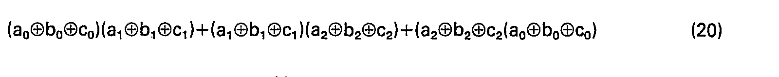
Dans un huitième mode de réalisation, selon l'invention, les trois registres ne comportent qu'une sortie et l'équation logique, dérivée du générateur de Geffe, est fonction de trois sorties ao, bo, c10 à l'instant to et de trois sorties a1, b1, c1 à l'instant to+1/F ou to-1/F et est de la forme:![]()
![]()
![]()
![]()
Dans un neuvième mode de réalisation, selon l'invention, le registre A comporte deux sorties, les registres B et C comportent chacun une sortie et l'équation logique, dérivée du générateur de Geffe, est fonction des valeurs ao, bo, co de trois sorties à l'instant to, des valeurs a1, b1, c1 de ces trois mêmes sorties à l'instant to+ 1/F et de la valeur a2 de la 2éme sortie du registre A à l'instant to ou to+1/F, et est de la forme:![]()
![]()
Dans les huitième et neuvième modes de réalisation, pour une période ligne
![]()

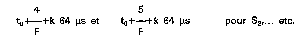
![]()
Dans un dixième mode de réalisation, selon l'invention, les trois registres ne comportent qu'une sortie et l'équation logique, dérivée du générateur de Geffe, est fonction de trois sorties ao, bo, co à l'instant to, de trois sorties a1, b1, c1 à l'instant

![]()
![]()
Dans un onzième et dernier mode de réalisation, selon l'invention, les trois registres ne comportent qu'une sortie et l'équation logique, dérivée du générateur de Brüer, est fonction de trois sorties ao, bo, co à l'instant to, de trois sorties a1, b1, c1 à l'instant
![]()
![]()
![]()
![]()
Dans ces deux derniers modes de réalisation, pour une période ligne


Bien entendu, dans les équations (17) à (20) précédentes, on a toute liberté pour choisir pour sorties a,, bj, ck soit des sorties directes des registres soit, pour partie ou totalité de ces coefficients, des compléments à 1 de ces sorties directes, compléments qui sont également disponibles dans la majorité des réalisations pratiques des registres à décalage.Of course, in equations (17) to (20) above, we are free to choose for outputs a ,, b j , c k either direct outputs from the registers or, for some or all of these coefficients, complements to 1 of these direct outputs, complements which are also available in the majority of practical realizations of shift registers.
Dans les cinquième à onzième modes de réalisation selon l'invention, il y a intérêt à ce que les séquences des adresses pseudoaléatoires soient les plus longues possibles, pour rendre le chiffrement le plus efficace. Une première condition est de choisir les longueurs na, nb et nc des registres telles que les longueurs des séquences que ces dernières fournissent, respectivement égales à (2na-1), (2"b-1), et (2n c-1), soient premières entre elles. La longueur des séquences de combinaisons de bits provenant des trois registres est alors maximale et égale au produit:![]()
![]()
Dans les cinquième, sixième et septième modes de réalisation selon l'invention, les coefficients des adresses sont calculés à partir de M sorties successives des registres. On pourrait donc retrouver les mêmes adresses en sorties toutes les![]()
![]()
![]()
![]()
![]()
![]()
![]()
![]()
Dans les huitième et neuvième modes de réalisation selon l'invention, les mêmes adresses pourraient revenir toutes les
Dans les dixième et onzième modes de réalisation selon l'invention, les mêmes adresses pourraient revenir toutes les![]()
![]()
Comme il peut arriver que certaines de ces conditions ne puissent pas être remplies, par exemple dans le cas où le nombre de bits de la clé nd=na+nb+nc est fixé et, en particulier, quand ce nombre est pair, on peut rendre encore la sécurité du système maximale en choisissant une fréquence d'échantillonnage F égale au produit de la fréquence F par un nombre qui est premier avec (2
Si l'on se place dans le cas des deux derniers modes de réalisation, avec M=8 par exemple, la fréquence la plus faible que l'on puisse choisir est:![]()
![]()
![]()

![]()
![]()
![]()
On peut enfin choisir la fraction par laquelle on multiplie F pour obtenir F de telle sorte que la fréquence horloge F soit égale à la fréquence horloge F' utilisée pour déchiffrer les canaux audio numériques, ou soit dans un rapport simple avec cette fréquence F'. Le générateur d'adresses numériques pseudo-aléatoires pourra alors être commun au déchiffrement du canal vidéo et au déchiffrement du ou des canaux audio associés à l'image.We can finally choose the fraction by which we multiply F to obtain F so that the clock frequency F is equal to the clock frequency F 'used to decipher the digital audio channels, or is in a simple relationship with this frequency F'. The pseudo-random digital address generator can then be common to the decryption of the video channel and to the decryption of the audio channel or channels associated with the image.
Claims (26)

Applications Claiming Priority (4)
| Application Number | Priority Date | Filing Date | Title |
|---|---|---|---|
| FR8221361 | 1982-12-20 | ||
| FR8221361A FR2538192B1 (en) | 1982-12-20 | 1982-12-20 | PSEUDOALEATORY DIGITAL SEQUENCE GENERATOR |
| FR8313540 | 1983-08-22 | ||
| FR8313540A FR2551235B1 (en) | 1983-08-22 | 1983-08-22 | PSEUDOALEATORY DIGITAL SEQUENCE GENERATOR |
Publications (2)
| Publication Number | Publication Date |
|---|---|
| EP0115097A1 EP0115097A1 (en) | 1984-08-08 |
| EP0115097B1 true EP0115097B1 (en) | 1987-06-03 |
Family
ID=26223195
Family Applications (1)
| Application Number | Title | Priority Date | Filing Date |
|---|---|---|---|
| EP83201780A Expired EP0115097B1 (en) | 1982-12-20 | 1983-12-15 | Generator of random number sequences |
Country Status (3)
| Country | Link |
|---|---|
| US (1) | US4649419A (en) |
| EP (1) | EP0115097B1 (en) |
| DE (1) | DE3371947D1 (en) |
Families Citing this family (20)
| Publication number | Priority date | Publication date | Assignee | Title |
|---|---|---|---|---|
| GB2184272A (en) * | 1985-11-25 | 1987-06-17 | Philips Electronic Associated | Interface between a receiver and a sub-system |
| US4866770A (en) * | 1986-07-08 | 1989-09-12 | Scientific Atlanta, Inc. | Method and apparatus for communication of video, audio, teletext, and data to groups of decoders in a communication system |
| US4771463A (en) * | 1986-12-05 | 1988-09-13 | Siemens Transmission Systems, Inc. | Digital scrambling without error multiplication |
| US4852023A (en) * | 1987-05-12 | 1989-07-25 | Communications Satellite Corporation | Nonlinear random sequence generators |
| US5412587A (en) * | 1988-12-28 | 1995-05-02 | The Boeing Company | Pseudorandom stochastic data processing |
| US5255378A (en) * | 1989-04-05 | 1993-10-19 | Intel Corporation | Method of transferring burst data in a microprocessor |
| US5131083A (en) * | 1989-04-05 | 1992-07-14 | Intel Corporation | Method of transferring burst data in a microprocessor |
| CH683580A5 (en) * | 1990-02-21 | 1994-03-31 | Kudelski Sa | Method and device for scrambling and descrambling a video signal. |
| FR2671647A1 (en) * | 1991-01-16 | 1992-07-17 | France Etat | PSEUDO-RANDOM GENERATOR. |
| US5235423A (en) * | 1991-08-16 | 1993-08-10 | The Grass Valley Group, Inc. | Controllable pseudo random noise pattern generator for use in video special effects |
| US5210770A (en) * | 1991-09-27 | 1993-05-11 | Lockheed Missiles & Space Company, Inc. | Multiple-signal spread-spectrum transceiver |
| EP0580870A4 (en) * | 1992-02-14 | 1994-06-08 | Advantest Corp | Multi-channel pseudo-random pattern generator |
| US6947560B1 (en) * | 1999-04-26 | 2005-09-20 | Telefonaktiebolaget L M Ericsson (Publ) | Method and device for effective key length control |
| KR100611955B1 (en) * | 1999-07-20 | 2006-08-11 | 삼성전자주식회사 | Scrambler |
| DE10339999B4 (en) * | 2003-08-29 | 2005-07-14 | Infineon Technologies Ag | Pseudorandom number generator |
| US8145691B2 (en) * | 2006-02-24 | 2012-03-27 | Novell, Inc. | Techniques for random bit generation |
| US8219782B2 (en) * | 2008-09-18 | 2012-07-10 | Xilinx, Inc. | Address generation |
| CA2664620A1 (en) | 2009-05-07 | 2009-07-20 | Avalon Microelectronics, Inc. | Pseudo-random bit sequence generator |
| US9954708B2 (en) | 2013-11-15 | 2018-04-24 | Intel Corporation | Method and apparatus for frequency interleaving |
| US10552988B2 (en) * | 2017-12-22 | 2020-02-04 | Intel Corporation | Ordering segments of an image for encoding and transmission to a display device |
Family Cites Families (6)
| Publication number | Priority date | Publication date | Assignee | Title |
|---|---|---|---|---|
| DE2547937B2 (en) * | 1975-10-25 | 1981-06-04 | Licentia Patent-Verwaltungs-Gmbh, 6000 Frankfurt | Method for generating random-like character strings |
| FR2431809A1 (en) * | 1978-07-20 | 1980-02-15 | Telediffusion Fse | TV receiver signals scrambler - divides video signal line into samples and cyclically interchanges time position of samples |
| US4459611A (en) * | 1978-08-28 | 1984-07-10 | Fuji Xerox Co., Ltd. | Image conversion system |
| US4329711A (en) * | 1979-02-20 | 1982-05-11 | Payview Limited | Apparatus for encoding of information |
| US4484027A (en) * | 1981-11-19 | 1984-11-20 | Communications Satellite Corporation | Security system for SSTV encryption |
| FR2533099A1 (en) * | 1982-09-14 | 1984-03-16 | Radiotechnique | METHOD FOR INTERRUPTING TELEVISION IMAGES AND DEVICE FOR DECHIFING IMAGES SO BROWNED |
-
1983
- 1983-12-15 DE DE8383201780T patent/DE3371947D1/en not_active Expired
- 1983-12-15 EP EP83201780A patent/EP0115097B1/en not_active Expired
-
1985
- 1985-12-17 US US06/810,529 patent/US4649419A/en not_active Expired - Fee Related
Also Published As
| Publication number | Publication date |
|---|---|
| DE3371947D1 (en) | 1987-07-09 |
| EP0115097A1 (en) | 1984-08-08 |
| US4649419A (en) | 1987-03-10 |
Similar Documents
| Publication | Publication Date | Title |
|---|---|---|
| EP0115097B1 (en) | Generator of random number sequences | |
| EP0740870B1 (en) | Method for the transmission and reception of conditional access programmes using control words specific to said programmes | |
| EP0426923B1 (en) | Compound video signal scrambling and unscrambling method and apparatus | |
| EP2052539B1 (en) | Method of revocation of security modules used to secure broadcast messages | |
| EP1827019A1 (en) | Conditional access method to conditional access data | |
| EP0618736A1 (en) | Method and device for scrambling and descrambling of a television transmission | |
| WO2003107585A1 (en) | Method for secure data exchange between two devices | |
| FR2496303A1 (en) | PUBLIC KEY ENCRYPTION / DATA ENCRYPTION SYSTEM | |
| EP0021938A1 (en) | Television system with access control using a variable electronic key | |
| EP0027423B1 (en) | Digital-signal ciphering and deciphering arrangement | |
| FR2905543A1 (en) | SECURITY PROCESSOR AND METHOD AND RECORDING MEDIUM FOR CONFIGURING THE BEHAVIOR OF THIS PROCESSOR. | |
| EP0126495B1 (en) | Descrambler for television pictures scrambled by circular permutation | |
| EP0375539B1 (en) | Method for scrambling and descrambling composite video signals, and apparatus therefor | |
| EP0083998B1 (en) | Scramble or unscramble byte generator | |
| WO2006061420A1 (en) | Method and system for encryption by a proxy | |
| FR2538192A1 (en) | Generator of pseudorandom digital sequences. | |
| EP1723790B1 (en) | Method for securing encrypted content broadcast by a broadcaster | |
| FR3108225A1 (en) | Fault detection by an electronic circuit | |
| WO2005099265A1 (en) | Method for securing a tv broadcast event | |
| FR2923968A1 (en) | Strong secret i.e. cryptographic key, sharing method for e.g. subscriber identity module card of mobile telephone, involves decrypting strong secret by asymmetric algorithm using private key such that parts are in strong secret possession | |
| FR2551235A1 (en) | Pseudorandom digital sequence generator. | |
| FR2833121A1 (en) | METHOD OF DISTRIBUTION OF SCRAPPED DIGITAL DATA ENCRYPTION KEYS | |
| EP2253142B1 (en) | Method of securing messages transmitted by a sender terminal to a remote receiver terminal | |
| WO2001089215A2 (en) | Method for transmitting encrypted data, use of same in a pay digital television system and decoder used in said system | |
| FR3068560A1 (en) | METHOD FOR RECEIVING AND DETECTING A CRYPTOGRAM OF A CONTROL WORD |
Legal Events
| Date | Code | Title | Description |
|---|---|---|---|
| PUAI | Public reference made under article 153(3) epc to a published international application that has entered the european phase |
Free format text: ORIGINAL CODE: 0009012 |
|
| AK | Designated contracting states |
Designated state(s): DE FR GB |
|
| 17P | Request for examination filed |
Effective date: 19841218 |
|
| 17Q | First examination report despatched |
Effective date: 19860527 |
|
| RAP1 | Party data changed (applicant data changed or rights of an application transferred) |
Owner name: S.A. LA RADIOTECHNIQUE INDUSTRIELLE ET COMMERCIALE |
|
| GRAA | (expected) grant |
Free format text: ORIGINAL CODE: 0009210 |
|
| AK | Designated contracting states |
Kind code of ref document: B1 Designated state(s): DE FR GB |
|
| REF | Corresponds to: |
Ref document number: 3371947 Country of ref document: DE Date of ref document: 19870709 |
|
| PLBE | No opposition filed within time limit |
Free format text: ORIGINAL CODE: 0009261 |
|
| STAA | Information on the status of an ep patent application or granted ep patent |
Free format text: STATUS: NO OPPOSITION FILED WITHIN TIME LIMIT |
|
| 26N | No opposition filed | ||
| REG | Reference to a national code |
Ref country code: FR Ref legal event code: CD |
|
| REG | Reference to a national code |
Ref country code: FR Ref legal event code: CD |
|
| PGFP | Annual fee paid to national office [announced via postgrant information from national office to epo] |
Ref country code: GB Payment date: 19911202 Year of fee payment: 9 |
|
| PGFP | Annual fee paid to national office [announced via postgrant information from national office to epo] |
Ref country code: FR Payment date: 19911218 Year of fee payment: 9 |
|
| PGFP | Annual fee paid to national office [announced via postgrant information from national office to epo] |
Ref country code: DE Payment date: 19920224 Year of fee payment: 9 |
|
| PG25 | Lapsed in a contracting state [announced via postgrant information from national office to epo] |
Ref country code: GB Effective date: 19921215 |
|
| GBPC | Gb: european patent ceased through non-payment of renewal fee |
Effective date: 19921215 |
|
| PG25 | Lapsed in a contracting state [announced via postgrant information from national office to epo] |
Ref country code: FR Effective date: 19930831 |
|
| PG25 | Lapsed in a contracting state [announced via postgrant information from national office to epo] |
Ref country code: DE Effective date: 19930901 |
|
| REG | Reference to a national code |
Ref country code: FR Ref legal event code: ST |