EP0114826B1 - Automatic hand firearm - Google Patents
Automatic hand firearm Download PDFInfo
- Publication number
- EP0114826B1 EP0114826B1 EP83900788A EP83900788A EP0114826B1 EP 0114826 B1 EP0114826 B1 EP 0114826B1 EP 83900788 A EP83900788 A EP 83900788A EP 83900788 A EP83900788 A EP 83900788A EP 0114826 B1 EP0114826 B1 EP 0114826B1
- Authority
- EP
- European Patent Office
- Prior art keywords
- slide
- operating handle
- face
- handle
- barrel
- Prior art date
- Legal status (The legal status is an assumption and is not a legal conclusion. Google has not performed a legal analysis and makes no representation as to the accuracy of the status listed.)
- Expired
Links
Images


Classifications
-
- F—MECHANICAL ENGINEERING; LIGHTING; HEATING; WEAPONS; BLASTING
- F41—WEAPONS
- F41A—FUNCTIONAL FEATURES OR DETAILS COMMON TO BOTH SMALLARMS AND ORDNANCE, e.g. CANNONS; MOUNTINGS FOR SMALLARMS OR ORDNANCE
- F41A3/00—Breech mechanisms, e.g. locks
- F41A3/64—Mounting of breech-blocks; Accessories for breech-blocks or breech-block mountings
- F41A3/72—Operating handles or levers; Mounting thereof in breech-blocks or bolts
-
- F—MECHANICAL ENGINEERING; LIGHTING; HEATING; WEAPONS; BLASTING
- F41—WEAPONS
- F41A—FUNCTIONAL FEATURES OR DETAILS COMMON TO BOTH SMALLARMS AND ORDNANCE, e.g. CANNONS; MOUNTINGS FOR SMALLARMS OR ORDNANCE
- F41A11/00—Assembly or disassembly features; Modular concepts; Articulated or collapsible guns
- F41A11/04—Articulated or collapsible guns, i.e. with hinged or telescopic parts for transport or storage
Definitions
- the present invention concerns an automatic hand firearm with mass obturation comprising a body with a handle, a barrel joined to the body, a slide with a guide and a return spring, a cocking and firing mechanism and an operating handle placed forward of the magazine, by which handle the front part of the gun can be supported during firing.
- Such firearms are well-known in pratice.
- Is is an object of the present invention to eliminate the drawback mentioned and to provide an automatic hand firearm where the slide can be made safe also in the forward position so that accidental movement of the slide into its rear position and loading of the gun is prevented.
- a further object of the invention is to provide an automatic hand firearm where unintentional forward and/or rearward movement of the slide is prevented.
- Another object of the invention is to provide an automatic hand firearm having, in addition to the conventional handle, a special operating handle, placed to advantage at the muzzle end of the barrel, to facilitate aiming when giving continuous fire.
- the automatic hand firearm according to the invention is characterized in that the operating handle is pivoted to the body with the aid of a slide member to be turnable from its transporting position substantially parallelling the barrel into a shooting position and movably turned out of its transporting position, that the slide member and the operating handle are movable in the direction of the barrel, that the slide can be pulled into a cocked rear position by the operating handle, and that the operating handle is provided at least with a safety member so disposed thatthe slide can be put on safety in the cocked rear position and/or in the uncocked forward position with the aid of the operating handle.
- the invention is based on a construction in which the operating handle has been pivoted to the body with the aid of a slide member to be turnable from its transporting position into the shooting position and to be movable in the longitudinal direction of the gun, that is in the direction parallel to the barrel.
- the slide member cooperates with the slide so that the slide can be cocked with the slide member and advantageously allowed to go into the forward position slowly under control by the slide member, without firing the gun.
- the operating handle has been provided with at least one safety member for putting the slide on safety and for locking it in the cocked rear position and/or in the uncocked forward position with the aid of the operating handle.
- Fig. 1 an automatic hand firearm with mass obturation, comprising a gun body 1 with a handle 2 and a barrel 3.
- the slide 4 has been disposed to be movable substantially parallel to the barrel, carried by the guide groove 5, and it has been provided with a return spring 6.
- the firearm furthermore comprises a cocking and firearm mechanism 7 and an operating handle 8 for cocking the slide.
- the slide 4 When using the firearm, the slide 4 is cocked in its rear position, where it is held by the cocking rest 20, removable by means of the firing mechanism 7.
- the slide is enabled to move forward, pushed by the force of the spring 6, whereat in its forward rush it takes a cartridge from the magazine, feeds it into the barrel and fires it.
- the recoil force from the round moves the slide into its rear position again.
- the operating handle 8 has been joined to the body 1 by the aid of a particular slide member 9, this slide member being carried in the body of the firearm and being, movable substantially in the direction of the barrel. It is thus understood that the slide member 9 and the operating handle 8 are movable in the direction of the barrel 3.
- the slide member 9 cooperates with the slide 4 in such manner that the slide can be pulled into its cocked rear position by pulling the operating handle and therewith the slide member, and thus the slide, into the rear position.
- the operating handle 8 has been provided with a safety member 10 (Figs. 2-4), which has beeen so disposed that the slide 4 can be put on safety in the cocked rear position and/or the uncocked forward position with the aid of the operating handle 8.
- Fig. 2 reveals the detailed construction of the operating handle 8.
- the safety member 10 consists of a shoulder comprising the bracing face of the barrel's 3 muzzle, that is the forward bracing face, 16 and/or the opposite, that is the rearward engagement face 13 having been so arranged that the slide is braced against said bracing face by mediation of said engagement face when it is substantially in its forward position and the bracing face prevents the rearward movement of the slide.
- the operating handle 8 has been pivoted to the slide member 9 to be turnable in a plane parallel to the barrel 3, and the safety member is constituted by the shoulder established on the lower end of the operating handle.
- the operating handle 8 has been pushed rearward and up, to parallel the barrel, so that the safety member 10 is pushed into a mating notch 25 formed on the slide, while the said forward bracing face pushes against the engagement face 13 and thus locks the slide in its forward position.
- the slide 4 is in its rear position, that is in cocked position, held for instance by the cocking rest 20 (see Fig. 1).
- the operating handle 8 has been turned rearwards and upwards to parallel the barrel 3, against the barrel, so that the safety member 10 has been pushed into the path of movement of the slide 4, and the slide rests by its latter bracing face 14 against the rearward, latter bracing face 17 of the safety member, whereby the safety member prevents the pushing forward of the slide 4 even if the trigger were pressed.
- the operating handle has been provided with a locking member, for instance a spring latch, for locking the handle in the position shown in Figs. 2 and 4.
- Fig. 3 illustrates how the slide is cocked with the aid of the operating handle 8.
- the slide member 9 has been provided witha bracing face 15, disposed on the path of motion of the slide 4 so that the engagement face 14 of the slide rests against the slide member by mediation of said bracing face.
- the slide member will move rearwards, thereby moving the slide further rearwards and into the locked rear position, to be held by the cocking rest 20 (Fig. 1).
- the slide member may thereafter be pushed into the forward position with the aid of the handle 8.
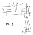
- the slide member 9 When shooting the firearm, the slide member 9 is pushed into the forward position and turned forwards as shown in Fig. 5, whereby the locking member 11, that is a ferrule pivoted to the slide member by means of an axle pin 12, turns along with the operating handle and the locking shoulder 22 enters behind a shoulder formed on the body, preventing the rearwards movement of the slide member, and thus of the operating handle.
- the locking is released by turning the operating handle 8 rearwards, causing the ferrule to be braced against the handle and to turn therewith, opening the locking.
- the operating handle has been locked to the ferrule, that is to the locking member 11, with the aid of a springloaded pin 18, which enters a groove 19 provided in the ferrule.
- the shoulder 21 establised on the body 1 and in support of which the slide member 9 can be locked with the aid of the locking member 11, is seen in Fig. 3.
- the locking member 11 has been formed of groove-like depression 26 made on the end of the operating handle.
- the part 27 of the firearm's body enters the recess 26 and locks the handle in the firing position when the handle is held in the forward position.
Landscapes
- Engineering & Computer Science (AREA)
- General Engineering & Computer Science (AREA)
- Toys (AREA)
- Containers And Packaging Bodies Having A Special Means To Remove Contents (AREA)
- Vending Machines For Individual Products (AREA)
Priority Applications (1)
| Application Number | Priority Date | Filing Date | Title |
|---|---|---|---|
| AT83900788T ATE21763T1 (de) | 1982-02-26 | 1983-02-25 | Automatische handfeuerwaffe. |
Applications Claiming Priority (2)
| Application Number | Priority Date | Filing Date | Title |
|---|---|---|---|
| FI820713A FI71011C (fi) | 1982-02-26 | 1982-02-26 | Automatiskt handeldvapen |
| FI820713 | 1983-02-26 |
Publications (2)
| Publication Number | Publication Date |
|---|---|
| EP0114826A1 EP0114826A1 (en) | 1984-08-08 |
| EP0114826B1 true EP0114826B1 (en) | 1986-08-27 |
Family
ID=8515154
Family Applications (1)
| Application Number | Title | Priority Date | Filing Date |
|---|---|---|---|
| EP83900788A Expired EP0114826B1 (en) | 1982-02-26 | 1983-02-25 | Automatic hand firearm |
Country Status (15)
| Country | Link |
|---|---|
| US (1) | US4555973A (fi) |
| EP (1) | EP0114826B1 (fi) |
| KR (1) | KR890000195B1 (fi) |
| AR (1) | AR230114A1 (fi) |
| AT (1) | ATE21763T1 (fi) |
| AU (1) | AU561177B2 (fi) |
| CA (1) | CA1221568A (fi) |
| DE (1) | DE3365524D1 (fi) |
| DK (1) | DK481983A (fi) |
| ES (1) | ES520091A0 (fi) |
| FI (1) | FI71011C (fi) |
| IT (1) | IT1161579B (fi) |
| MX (1) | MX155517A (fi) |
| NO (1) | NO152428C (fi) |
| WO (1) | WO1983002998A1 (fi) |
Families Citing this family (7)
| Publication number | Priority date | Publication date | Assignee | Title |
|---|---|---|---|---|
| US4823671A (en) * | 1987-11-20 | 1989-04-25 | Frank Buryta | Device for manually recoiling slide action pistols |
| DE69637890D1 (de) | 1995-06-07 | 2009-05-14 | Progenics Pharm Inc | Monoklonaler antikörper für die inhibierung von hiv-1-hüllgykoprotein-vermittelte membranfusion |
| DE10122345C1 (de) | 2001-05-09 | 2002-10-31 | Heckler & Koch Gmbh | Maschinengewehr mit Spannschieber |
| KR101586701B1 (ko) * | 2010-01-21 | 2016-01-19 | 한화테크윈 주식회사 | 차량 장착 장비 운용자용 안전장치 |
| US10066900B2 (en) * | 2014-07-04 | 2018-09-04 | Barrett Bowers | Firearm stabilizer |
| CZ306500B6 (cs) * | 2015-11-05 | 2017-02-15 | Viktor Shamrai | Samonabíjecí pistole |
| US10907916B2 (en) * | 2017-07-19 | 2021-02-02 | Hush Puppy Project LLC. | Slide block mechanism for semi-automatic pistols |
Family Cites Families (11)
| Publication number | Priority date | Publication date | Assignee | Title |
|---|---|---|---|---|
| US1460415A (en) * | 1922-07-12 | 1923-07-03 | Walter T Gorton | Operating slide and handle for machine guns |
| BE384805A (fi) * | 1930-12-09 | |||
| US2056577A (en) * | 1933-03-11 | 1936-10-06 | Waffenfabrik Solothurn Ag | Cocking device for automatic firearms having a sliding barrel and a bolted breech |
| DE972985C (de) * | 1942-08-05 | 1959-11-12 | Paul Kurt Johannes Grossfuss | Spannschieber fuer Maschinengewehre |
| US2480328A (en) * | 1944-07-13 | 1949-08-30 | Gen Motors Corp | Firing mechanism for recoilless shoulder mounted guns |
| US2679123A (en) * | 1948-08-20 | 1954-05-25 | Olin Ind Inc | Takedown mechanism for firearms |
| US2547180A (en) * | 1948-12-20 | 1951-04-03 | Frank S Taylor | Rifle construction |
| US3906833A (en) * | 1973-01-31 | 1975-09-23 | Hector Mendoza Orozco | Portable submachine gun |
| DE2902738C2 (de) * | 1978-02-10 | 1985-02-07 | Fabbrica d'Armi Pietro Beretta S.p.A., Gardone Val Trompia, Brescia | Abnehmbare Schulterstütze für Pistolen |
| US4176584A (en) * | 1978-06-21 | 1979-12-04 | Thomas Frank S Jr | Slide locking mechanism for magazine-fed firearms |
| DE3160427D1 (en) * | 1980-03-26 | 1983-07-21 | Oerlikon Buehrle Ag | Firing safety device for automatic gun |
-
1982
- 1982-02-26 FI FI820713A patent/FI71011C/fi not_active IP Right Cessation
-
1983
- 1983-02-23 CA CA000422175A patent/CA1221568A/en not_active Expired
- 1983-02-25 IT IT19802/83A patent/IT1161579B/it active
- 1983-02-25 KR KR1019830000768A patent/KR890000195B1/ko not_active IP Right Cessation
- 1983-02-25 MX MX196390A patent/MX155517A/es unknown
- 1983-02-25 AU AU12290/83A patent/AU561177B2/en not_active Ceased
- 1983-02-25 DE DE8383900788T patent/DE3365524D1/de not_active Expired
- 1983-02-25 AT AT83900788T patent/ATE21763T1/de not_active IP Right Cessation
- 1983-02-25 US US06/551,995 patent/US4555973A/en not_active Expired - Fee Related
- 1983-02-25 EP EP83900788A patent/EP0114826B1/en not_active Expired
- 1983-02-25 WO PCT/FI1983/000017 patent/WO1983002998A1/en active IP Right Grant
- 1983-02-25 ES ES520091A patent/ES520091A0/es active Granted
- 1983-02-25 AR AR292230A patent/AR230114A1/es active
- 1983-10-20 DK DK481983A patent/DK481983A/da not_active Application Discontinuation
- 1983-10-25 NO NO833888A patent/NO152428C/no unknown
Also Published As
| Publication number | Publication date |
|---|---|
| DK481983D0 (da) | 1983-10-20 |
| DK481983A (da) | 1983-10-20 |
| NO152428C (no) | 1985-09-25 |
| ES8402928A1 (es) | 1984-03-01 |
| KR890000195B1 (ko) | 1989-03-10 |
| FI71011B (fi) | 1986-07-18 |
| AR230114A1 (es) | 1984-02-29 |
| NO152428B (no) | 1985-06-17 |
| ES520091A0 (es) | 1984-03-01 |
| US4555973A (en) | 1985-12-03 |
| DE3365524D1 (en) | 1986-10-02 |
| WO1983002998A1 (en) | 1983-09-01 |
| ATE21763T1 (de) | 1986-09-15 |
| FI820713L (fi) | 1983-08-27 |
| AU561177B2 (en) | 1987-04-30 |
| NO833888L (no) | 1983-10-25 |
| KR840003765A (ko) | 1984-09-15 |
| FI71011C (fi) | 1986-10-27 |
| IT8319802A0 (it) | 1983-02-25 |
| MX155517A (es) | 1988-03-22 |
| EP0114826A1 (en) | 1984-08-08 |
| AU1229083A (en) | 1983-09-08 |
| CA1221568A (en) | 1987-05-12 |
| IT1161579B (it) | 1987-03-18 |
Similar Documents
| Publication | Publication Date | Title |
|---|---|---|
| US4567810A (en) | Automatic firearm | |
| US10514223B1 (en) | Firearm trigger mechanism | |
| US5906066A (en) | Automatic pistol mechanism | |
| US4579037A (en) | Machine pistol with retarded blowback | |
| US7337574B2 (en) | Frame for a firearm | |
| US20060048425A1 (en) | Forwardly-placed firearm fire control assembly | |
| US20060048427A1 (en) | Firearm trigger assembly | |
| GB1439309A (en) | Semi-automatic firearm | |
| US20060048426A1 (en) | Separating firearm sear | |
| WO1981003376A1 (en) | Semi-automatic firearms | |
| US3641694A (en) | Self-loading pistol with continuous firing device | |
| US3540142A (en) | Bolt stop mechanism | |
| US20230221087A1 (en) | Firearm trigger mechanism | |
| EP0114826B1 (en) | Automatic hand firearm | |
| US2699006A (en) | Firearm of the repearter gun type | |
| US4646619A (en) | Singulating apparatus for a semiautomatic firearm | |
| US4920676A (en) | Pistol with an interchangeable barrel | |
| US4531446A (en) | Machine gun adaptor | |
| US4821621A (en) | Multipurpose repeating firearm having alternate firing mechanisms | |
| GB1560848A (en) | Self-loading pistol | |
| US5463828A (en) | Shot gun | |
| US3866516A (en) | Semi-automatic piston employing a pivotally, slideable member | |
| US4899477A (en) | Hand-held automatic firearm | |
| US4730538A (en) | Safety device for automatic firearms | |
| US2835998A (en) | Slidable barrel gun with a combined sear and cocking member |
Legal Events
| Date | Code | Title | Description |
|---|---|---|---|
| PUAI | Public reference made under article 153(3) epc to a published international application that has entered the european phase |
Free format text: ORIGINAL CODE: 0009012 |
|
| 17P | Request for examination filed |
Effective date: 19840326 |
|
| AK | Designated contracting states |
Designated state(s): AT BE CH DE FR GB LI NL SE |
|
| GRAA | (expected) grant |
Free format text: ORIGINAL CODE: 0009210 |
|
| AK | Designated contracting states |
Kind code of ref document: B1 Designated state(s): AT BE CH DE FR GB LI NL SE |
|
| PG25 | Lapsed in a contracting state [announced via postgrant information from national office to epo] |
Ref country code: NL Effective date: 19860827 Ref country code: BE Effective date: 19860827 |
|
| REF | Corresponds to: |
Ref document number: 21763 Country of ref document: AT Date of ref document: 19860915 Kind code of ref document: T |
|
| REF | Corresponds to: |
Ref document number: 3365524 Country of ref document: DE Date of ref document: 19861002 |
|
| ET | Fr: translation filed | ||
| NLV1 | Nl: lapsed or annulled due to failure to fulfill the requirements of art. 29p and 29m of the patents act | ||
| PGFP | Annual fee paid to national office [announced via postgrant information from national office to epo] |
Ref country code: AT Payment date: 19870226 Year of fee payment: 5 |
|
| PLBE | No opposition filed within time limit |
Free format text: ORIGINAL CODE: 0009261 |
|
| STAA | Information on the status of an ep patent application or granted ep patent |
Free format text: STATUS: NO OPPOSITION FILED WITHIN TIME LIMIT |
|
| 26N | No opposition filed | ||
| PG25 | Lapsed in a contracting state [announced via postgrant information from national office to epo] |
Ref country code: AT Effective date: 19880225 |
|
| PG25 | Lapsed in a contracting state [announced via postgrant information from national office to epo] |
Ref country code: SE Effective date: 19880226 |
|
| PG25 | Lapsed in a contracting state [announced via postgrant information from national office to epo] |
Ref country code: LI Effective date: 19880229 Ref country code: CH Effective date: 19880229 |
|
| PG25 | Lapsed in a contracting state [announced via postgrant information from national office to epo] |
Ref country code: FR Free format text: LAPSE BECAUSE OF NON-PAYMENT OF DUE FEES Effective date: 19881028 |
|
| REG | Reference to a national code |
Ref country code: CH Ref legal event code: PL |
|
| PG25 | Lapsed in a contracting state [announced via postgrant information from national office to epo] |
Ref country code: DE Effective date: 19881101 |
|
| GBPC | Gb: european patent ceased through non-payment of renewal fee | ||
| PG25 | Lapsed in a contracting state [announced via postgrant information from national office to epo] |
Ref country code: GB Free format text: LAPSE BECAUSE OF NON-PAYMENT OF DUE FEES Effective date: 19881122 |
|
| REG | Reference to a national code |
Ref country code: FR Ref legal event code: ST |
|
| EUG | Se: european patent has lapsed |
Ref document number: 83900788.7 Effective date: 19880927 |