EP0114629B1 - Apparatus for weighing material - Google Patents
Apparatus for weighing material Download PDFInfo
- Publication number
- EP0114629B1 EP0114629B1 EP84100367A EP84100367A EP0114629B1 EP 0114629 B1 EP0114629 B1 EP 0114629B1 EP 84100367 A EP84100367 A EP 84100367A EP 84100367 A EP84100367 A EP 84100367A EP 0114629 B1 EP0114629 B1 EP 0114629B1
- Authority
- EP
- European Patent Office
- Prior art keywords
- scale
- weight
- set forth
- routes
- enabling signals
- Prior art date
- Legal status (The legal status is an assumption and is not a legal conclusion. Google has not performed a legal analysis and makes no representation as to the accuracy of the status listed.)
- Expired
Links
Images

Classifications
-
- G—PHYSICS
- G01—MEASURING; TESTING
- G01G—WEIGHING
- G01G19/00—Weighing apparatus or methods adapted for special purposes not provided for in the preceding groups
- G01G19/40—Weighing apparatus or methods adapted for special purposes not provided for in the preceding groups with provisions for indicating, recording, or computing price or other quantities dependent on the weight
- G01G19/42—Weighing apparatus or methods adapted for special purposes not provided for in the preceding groups with provisions for indicating, recording, or computing price or other quantities dependent on the weight for counting by weighing
-
- G—PHYSICS
- G01—MEASURING; TESTING
- G01G—WEIGHING
- G01G11/00—Apparatus for weighing a continuous stream of material during flow; Conveyor belt weighers
- G01G11/14—Apparatus for weighing a continuous stream of material during flow; Conveyor belt weighers using totalising or integrating devices
-
- G—PHYSICS
- G01—MEASURING; TESTING
- G01G—WEIGHING
- G01G13/00—Weighing apparatus with automatic feed or discharge for weighing-out batches of material
- G01G13/02—Means for automatically loading weigh pans or other receptacles, e.g. disposable containers, under control of the weighing mechanism
- G01G13/022—Material feeding devices
Definitions
- the present invention relates very generally to an apparatus for weighing material, and pertains, more particularly, to an apparatus for separately weighing contributions of material from multiple streams thereof and carrying out this separate weighing using a common scale.
- a common method for counting "good” products or materials from a printing press is with the use of two counters.
- One of these is a gross counter which counts every revolution of the press whether a "good” product is produced or whether the product is to be discarded.
- the other counter is a net counter.
- the net counter can be turned on and off by the press operator, in accordance with whether he thinks the copies being made are acceptable or not.
- the problem with this technique is that it is subject to error as the operator may be unaware that the press has started to produce copies that should be discarded and therefore the operator may fail to set the counter. It is typical that when the defect is discovered, that the operator may estimate the number in order to prevent the necessity of restarting the net counter when good copies are again produced.
- ratio scales have been employed to measure the number of signatures (impressions or sheets in the case of paper) discarded. The number so determined is subtracted from the gross count to obtain a more accurate net count. Alternatively, when the number of signatures discarded is determined from the ratio scale, this may be added to the required number of "good" counts in order to determine the gross counter reading at which the press is to be stopped.
- this technique is somewhat of an improvement, it is still subject to human error because of the bookkeeping involved. Also, because one printing press typically produces up to four different products at one time, the bookkeeping becomes particularly complicated. Also, the bookkeeping or record keeping is complicated by virtue of the fact that usually only one scale is used to measure the waste paper from several deliveries of the same press.
- Another technique that is employed involves the use of separate scales for each product. However, this technique requires substantial floor space and is also very expensive to implement. Still another common technique is to employ one scale but with multiple operator buttons such as four operator buttons to allow the pressman to enter which printing stream the last weight came from. This technique require too much operator involvement and slows the process since several people may be depositing sheets at one time.
- a variation of these techniques uses a small scale or scales to weight the individual bundles before they are deposited in the central bin. This variation has all the above-mentioned problems and further requires an extra step.
- a further object of the present invention is to provide an apparatus for separately weighing contributions of material, typically in sheet form from a printing press, from multiple streams thereof, and providing this weighing with a common scale.
- Another object of this invention is to provide an apparatus for registering accurate "good" counts for each of multiple press deliveries using a common scale.
- a further object of the present invention is to provide an improved apparatus for weighing material in accordance without the preceding objects and in which the method is carried out with the need for manual recording keeping or manual entry of data.
- Still another object of the present invention is to provide an improved apparatus for weighing materials from multiple streams with a common scale and wherein the apparatus is safe to operate, jamproof, accurate in operation, and easy to maintain.
- This apparatus comprises, in addition to common scale means, means responsive to the scale means for sensing increments in scale weight associated with each respective stream.
- the material that is being weighed is delivered by workers or operators along multiple respective routes to the common scale bin.
- the material may be in the form of paper used in a printing process and the weighing may be of spoiled product.
- the apparatus of this invention also comprises means worker initiated, to provide enabling signals respectively associated with the multiple routes, and means responsive to the means for sensing increments and to these enabling signals for providing a plurality of separate counts corresponding to weight for each respective route.
- weight additions are identified as to source by the operator operating any one of a number of different devices.
- Another embodiment may employ a photodetector that indicates on which route the operator is approaching. Thus, when the operator picks up waste from one delivery, he approaches the waste bin and scale on a predetermined route, thus actuating one of these means that is worker initiated.
- the electronics of the system which includes a computer utilizes this route-of-approach information in determining which delivery with which to associate the increment of waste just received.
- the means for sensing increments in scale weight may comprise a difference means or a different circuit having an output count or magnitude corresponding to the different weight between a present scale weight and the next scale weight.
- means are provided for converting the weight factor sensed to a count that corresponds to the number of pieces of material released in a batch.
- There is provided a means for totaling counts so as to display a count indicating total pieces weighed per stream. The aforementioned enabling signal determines which of the counters and associated displays is incremented.
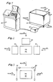
- Figure 1 shows an embodiment of the invention in which the recording of which stream the material comes from is determined by the person delivering the material.
- the embodiment of Fig. 1 shows the use of pushbuttons for activating the circuitry.
- Fig. 1 shows the general components of the system including a console 50, scale electronics 52, scale 54, and common storage bin 56.
- the storage bin 56 may be adapted to contain waste paper discharged in a printing press operation.
- the bin 56 rests upon the scale 54, only a portion of which is actually shown in the perspective view of Fig. 1.
- the scale 54 may be of conventional design adapted to have some type of a digital read-out such as a binary form indicative of weight.
- the apparatus disclosed in figure 1 may be used with a printing press which typically has three different conveyors upon which three different products may be delivered.
- the good products are allowed to go to stackers or bundlers not specifically described herein and are ultimately stacked on skids for future use or processing.
- the rejected products are lifted off the conveyors and placed in the apparatus depicted in figure 1.
- Fig. 1 Also illustrated in Fig. 1 are the three routes A, B, and C showing the different approaches that an operator may take to the storage bind 56.
- the registering of the weight increment is controlled by a series of pushbuttons such as the pushbutton 58 shown in Fig. 1.
- pushbuttons associated with routes A and B not specifically depicted in Fig. 1.
- route C will substantially concurrently deposit the waste material in the bin 56 and operate the pushbutton 58.
- the pushbutton 58 is provided hereinafter, a further discussion of the pushbutton 58 particularly with regard to the operation of the circuitry of Figs. 4 and 5.
- Figs. 2 and 3 show an embodiment in schematic fashion illustrating the bin 56 and similar routes A, B, and C.
- floor mats 60 one associated with each of the routes.
- These floor mats can be of conventional design and may be similar to those used in internal burglary systems, including some type of a responsive switch, so that as soon as the operator stands on the floor mat associated with his particular route, then an enabling signal is generated.
- enabling signals are illustrated in Fig. 4 and discussed hereinafter as signals E1, E2, and E3, associated with three different respective routes.
- FIG. 3 there is shown a similar schematic diagram as depicted in Fig. 2, but including, in place of the floor mats 60, photodetector units 62 which also may be of conventional design. With this arrangement, as soon as the operator or worker passes across the beam of the photodetector, then a circuit is set off to provide an enabling signal which once again are the signal E1 ⁇ E3 shown in Fig. 4.
- Fig. 4 there is shown control electronics used in carrying out the system of this invention. It is understood that some of the control may be provided by computer. However, in Fig. 4 it is the intention to show the basic circuitry that is usable in practicing the concepts of the invention.
- the scale 70 which has an output on line 71 representative of the weight on the scale. Digital scales are well known and the output signal on line 71 may in fact be a multi-line signal representative of a count corresponding to weight. This may be a binary signal.
- This signal is coupled to the difference device 72 which again may be a conventional device in the form of a subtractor or the like device which may have a clock input and also has storage capability.
- the difference device 72 simply stores an indication of the present count and then compares that with a subsequent count under control, perhaps of a system clock. This thus provides an output at the line 73 from the device 72 that is representative of the increment in weight in the form of an increment count corresponding to the weight added each time that an operator discharges or delivers material into the waste bin.
- the device 72 does not distinguish as to the origin of the waste delivery, but simply provides a difference signal that is coupled by way of line 73 to a magnitude converter 74.
- the magnitude converter 74 provides for any necessary conversion from weight to a count representative of the number of signatures (impressions or sheets of paper).
- the output signal from the converter 74 couples by way of line 75 to a series of gates G1, G2, and G3.
- Fig. 4 These are represented in Fig. 4 as AND gates that also receive the respective enabling signals E1, E2, and E3.
- the demarcation of weight increment is carried out by the gates which are mutually exclusively enabled by respective -signals El-E3.
- the output of the gates G1 ⁇ G3 couple to the adders Al-A3 for providing total respective counts of total signatures per stream.
- the three adders Al-A3 then are shown coupling to the three display devices Dl-D3.
- the gates, adders and display devices correspond in number to the number of routes that are employed. Because in the illustrated embodiment, three routes A, B and C have been used, then there are three of each of these devices. It should also be understood that the signals E1 ⁇ E3 are enabling signals.
- the other inputs to the gates may actually be multiple inputs, there being provided a multi-line parallel input to the adders.
- the gates may be enabled to provide a series of counts to be coupled thereby into the adders for providing incrementing thereof. In either case, the adding of the adders is enabled only by each of the respective signals, E1, E2, and E3.
- Fig. 5 shows one simple embodiment showing a switch S1 which may be one of the switches of one of the floor mats 60 or may be one of the pushbuttons 58 shown in Fig. 1.
- This switch is shown coupling on one side to a voltage supply and on the other side to the multivibrator 80.
- This may be a monostable multivibrator or possibly a bistable multivibrator
- the output of the multivibrator 80 is identified as the signal E1 which is an enabling signal.
Landscapes
- Physics & Mathematics (AREA)
- General Physics & Mathematics (AREA)
- Engineering & Computer Science (AREA)
- Mathematical Physics (AREA)
- Theoretical Computer Science (AREA)
- Sorting Of Articles (AREA)
- Weight Measurement For Supplying Or Discharging Of Specified Amounts Of Material (AREA)
- Controlling Sheets Or Webs (AREA)
Description
- The present invention relates very generally to an apparatus for weighing material, and pertains, more particularly, to an apparatus for separately weighing contributions of material from multiple streams thereof and carrying out this separate weighing using a common scale.
- In the printing process, and in other production processes, particularly where a continuous supply of material, such as paper from a roll is fed through a printing press, it is desired to maintain an accurate count of the products from the production process. As long as all of the products from the process are usable, in the case of the printing process, the count is equal to the number of revolutions of the printing press. However, it typically happens that in the course of carrying out the process, some of the products or materials are spoiled for one reason or the other and must be discarded. Thus, the total count of press impressions is no longer a measure of the total count of good product produced. It is and has been thus necessary either to count the good product independently, or to maintain an accurate accounting of the number of products discarded, so that this number can be subtracted from the known total count to obtain an accurate figure for the net "good" count.
- A common method for counting "good" products or materials from a printing press is with the use of two counters. One of these is a gross counter which counts every revolution of the press whether a "good" product is produced or whether the product is to be discarded. The other counter is a net counter. The net counter can be turned on and off by the press operator, in accordance with whether he thinks the copies being made are acceptable or not. The problem with this technique is that it is subject to error as the operator may be unaware that the press has started to produce copies that should be discarded and therefore the operator may fail to set the counter. It is typical that when the defect is discovered, that the operator may estimate the number in order to prevent the necessity of restarting the net counter when good copies are again produced.
- To overcome the aforementioned problem, ratio scales have been employed to measure the number of signatures (impressions or sheets in the case of paper) discarded. The number so determined is subtracted from the gross count to obtain a more accurate net count. Alternatively, when the number of signatures discarded is determined from the ratio scale, this may be added to the required number of "good" counts in order to determine the gross counter reading at which the press is to be stopped. Although this technique is somewhat of an improvement, it is still subject to human error because of the bookkeeping involved. Also, because one printing press typically produces up to four different products at one time, the bookkeeping becomes particularly complicated. Also, the bookkeeping or record keeping is complicated by virtue of the fact that usually only one scale is used to measure the waste paper from several deliveries of the same press.
- Another technique that is employed involves the use of separate scales for each product. However, this technique requires substantial floor space and is also very expensive to implement. Still another common technique is to employ one scale but with multiple operator buttons such as four operator buttons to allow the pressman to enter which printing stream the last weight came from. This technique require too much operator involvement and slows the process since several people may be depositing sheets at one time. A variation of these techniques uses a small scale or scales to weight the individual bundles before they are deposited in the central bin. This variation has all the above-mentioned problems and further requires an extra step.
- In EP-A2-111805 published 27 June 1984 there is described a method and associated apparatus for separately weighing contributions of material from multiple streams thereof, using a common scale. In this earlier application there is provided a plurality of separate means, each for the temporary storage of a quantity of the material that is to be weighed. The apparatus also comprises means for sequentially releasing the material from the respective separate means for storing so as to enable delivery thereof to the common scale means. This is accomplished under electronic control, including means responsive to the scale reading for sensing increments in scale weight for each respective release of material. Also this technique is an effective way of weighing materials from separate streams using a common scale, the releasing step is carried out automatically and cyclically and thus there are instances wherein a releasing step takes place even though there is no material at the station to be released.
- Accordingly, it is an object of the present invention to provide an improved apparatus for separately weighing contributions of material from multiple streams in which each separate weighing takes place upon operator command rather than on a sequential or cyclic basis.
- A further object of the present invention is to provide an apparatus for separately weighing contributions of material, typically in sheet form from a printing press, from multiple streams thereof, and providing this weighing with a common scale.
- Another object of this invention is to provide an apparatus for registering accurate "good" counts for each of multiple press deliveries using a common scale.
- A further object of the present invention is to provide an improved apparatus for weighing material in accordance without the preceding objects and in which the method is carried out with the need for manual recording keeping or manual entry of data.
- Still another object of the present invention is to provide an improved apparatus for weighing materials from multiple streams with a common scale and wherein the apparatus is safe to operate, jamproof, accurate in operation, and easy to maintain.
- To accomplish the foregoing and other objects of this invention there is provided in accordance with one aspect of the invention, apparatus for weighing material from multiple streams with a common scale as defined in
claim 1. This apparatus comprises, in addition to common scale means, means responsive to the scale means for sensing increments in scale weight associated with each respective stream. The material that is being weighed is delivered by workers or operators along multiple respective routes to the common scale bin. In the embodiment described herein, the material may be in the form of paper used in a printing process and the weighing may be of spoiled product. The apparatus of this invention also comprises means worker initiated, to provide enabling signals respectively associated with the multiple routes, and means responsive to the means for sensing increments and to these enabling signals for providing a plurality of separate counts corresponding to weight for each respective route. More particularly, weight additions are identified as to source by the operator operating any one of a number of different devices. For example, there may be associated with the bin, three different routes, with each having a pushbutton associated therewith, which button is depressed substantially concurrently with the addition of the material by the worker or operator. In alternate embodiments, instead of pushbuttons, there may be provided floor pads with switches therein upon which the operator stands. Another embodiment may employ a photodetector that indicates on which route the operator is approaching. Thus, when the operator picks up waste from one delivery, he approaches the waste bin and scale on a predetermined route, thus actuating one of these means that is worker initiated. The electronics of the system which includes a computer utilizes this route-of-approach information in determining which delivery with which to associate the increment of waste just received. The means for sensing increments in scale weight may comprise a difference means or a different circuit having an output count or magnitude corresponding to the different weight between a present scale weight and the next scale weight. Preferably, means are provided for converting the weight factor sensed to a count that corresponds to the number of pieces of material released in a batch. There is provided a means for totaling counts so as to display a count indicating total pieces weighed per stream. The aforementioned enabling signal determines which of the counters and associated displays is incremented. - Numerous other objects, features and advantages of the invention should now become apparent upon a reading of the following detailed description taken in conjunction with the accompanying drawing, in which:
- Fig. 1 is a perspective view showing the control console, scale electronics, and associated scale with scale bin in connection with the preferred embodiment described herein in which deliveries to the common bin occur along predetermined routes;
- Fig. 2 is a schematic plan view showing the use of floor mats with switches for providing an indication of passage by an operator worker along a route;
- Fig. 3 is a schematic plan view of an alternate embodiment employing photodetectors in place of the floor mats shown in Fig. 2;
- Fig. 4 is a block diagram associated with the invention showing the electronics involved in providing total weight displays; and
- Fig. 5 is a simplified block diagram showing the manner in which the pushbutton technique couples with the circuitry of Fig. 4.
- Referring now to the drawing, Figure 1 shows an embodiment of the invention in which the recording of which stream the material comes from is determined by the person delivering the material. The embodiment of Fig. 1 shows the use of pushbuttons for activating the circuitry. Fig. 1 shows the general components of the system including a
console 50,scale electronics 52,scale 54, andcommon storage bin 56. Thestorage bin 56 may be adapted to contain waste paper discharged in a printing press operation. Thebin 56 rests upon thescale 54, only a portion of which is actually shown in the perspective view of Fig. 1. Thescale 54 may be of conventional design adapted to have some type of a digital read-out such as a binary form indicative of weight. - The apparatus disclosed in figure 1 may be used with a printing press which typically has three different conveyors upon which three different products may be delivered. The good products are allowed to go to stackers or bundlers not specifically described herein and are ultimately stacked on skids for future use or processing. The rejected products are lifted off the conveyors and placed in the apparatus depicted in figure 1.
- Also illustrated in Fig. 1 are the three routes A, B, and C showing the different approaches that an operator may take to the
storage bind 56. In the example of figure 1, the registering of the weight increment is controlled by a series of pushbuttons such as thepushbutton 58 shown in Fig. 1. There are also similar pushbuttons associated with routes A and B not specifically depicted in Fig. 1. Thus, the operator as he approaches along say route C will substantially concurrently deposit the waste material in thebin 56 and operate thepushbutton 58. There is provided hereinafter, a further discussion of thepushbutton 58 particularly with regard to the operation of the circuitry of Figs. 4 and 5. - Alternate means that are worker initiated to provide an enabling signal are shown in Figs. 2 and 3. Fig. 2 shows an embodiment in schematic fashion illustrating the
bin 56 and similar routes A, B, and C. In the embodiment of Fig. 2, there are providedfloor mats 60, one associated with each of the routes. These floor mats can be of conventional design and may be similar to those used in internal burglary systems, including some type of a responsive switch, so that as soon as the operator stands on the floor mat associated with his particular route, then an enabling signal is generated. These enabling signals are illustrated in Fig. 4 and discussed hereinafter as signals E1, E2, and E3, associated with three different respective routes. - Now, in Fig. 3, there is shown a similar schematic diagram as depicted in Fig. 2, but including, in place of the
floor mats 60,photodetector units 62 which also may be of conventional design. With this arrangement, as soon as the operator or worker passes across the beam of the photodetector, then a circuit is set off to provide an enabling signal which once again are the signal E1―E3 shown in Fig. 4. - With respect to Fig. 4, there is shown control electronics used in carrying out the system of this invention. It is understood that some of the control may be provided by computer. However, in Fig. 4 it is the intention to show the basic circuitry that is usable in practicing the concepts of the invention. Thus, in Fig. 4 there is illustrated the
scale 70 which has an output online 71 representative of the weight on the scale. Digital scales are well known and the output signal online 71 may in fact be a multi-line signal representative of a count corresponding to weight. This may be a binary signal. This signal is coupled to thedifference device 72 which again may be a conventional device in the form of a subtractor or the like device which may have a clock input and also has storage capability. Thedifference device 72 simply stores an indication of the present count and then compares that with a subsequent count under control, perhaps of a system clock. This thus provides an output at theline 73 from thedevice 72 that is representative of the increment in weight in the form of an increment count corresponding to the weight added each time that an operator discharges or delivers material into the waste bin. In the embodiment of Fig. 4, thedevice 72 does not distinguish as to the origin of the waste delivery, but simply provides a difference signal that is coupled by way ofline 73 to amagnitude converter 74. Themagnitude converter 74 provides for any necessary conversion from weight to a count representative of the number of signatures (impressions or sheets of paper). The output signal from theconverter 74 couples by way ofline 75 to a series of gates G1, G2, and G3. These are represented in Fig. 4 as AND gates that also receive the respective enabling signals E1, E2, and E3. Thus, the demarcation of weight increment is carried out by the gates which are mutually exclusively enabled by respective -signals El-E3. The output of the gates G1―G3 couple to the adders Al-A3 for providing total respective counts of total signatures per stream. The three adders Al-A3 then are shown coupling to the three display devices Dl-D3. The gates, adders and display devices, correspond in number to the number of routes that are employed. Because in the illustrated embodiment, three routes A, B and C have been used, then there are three of each of these devices. It should also be understood that the signals E1―E3 are enabling signals. The other inputs to the gates may actually be multiple inputs, there being provided a multi-line parallel input to the adders. In an alternate embodiment, the gates may be enabled to provide a series of counts to be coupled thereby into the adders for providing incrementing thereof. In either case, the adding of the adders is enabled only by each of the respective signals, E1, E2, and E3. - Fig. 5 shows one simple embodiment showing a switch S1 which may be one of the switches of one of the
floor mats 60 or may be one of thepushbuttons 58 shown in Fig. 1. This switch is shown coupling on one side to a voltage supply and on the other side to themultivibrator 80. This may be a monostable multivibrator or possibly a bistable multivibrator It is noted that the output of themultivibrator 80 is identified as the signal E1 which is an enabling signal. Thus, when the switch S1 associated with say, route A, is operated by the operator and assuming that the waste material is now in the bin, there is an increment signal coupled to all three of the gates. However, because only the switch S1 has been actuated, only the enable signal E1 is generated and thus the totaling of counts only occurs by way of the first adder A1 and associated display device D1. Similar switch and multivibrator circuits are used also in connection with the generation of the signals E2 and E3 and any additional enable signals that are provided as the number of paths or routes may increase. - Having described one embodiment of the present invention, it should now be apparent to those skilled in the art that numerous other embodiments are contemplated as falling within the claims.
Claims (8)
Applications Claiming Priority (2)
| Application Number | Priority Date | Filing Date | Title |
|---|---|---|---|
| US06/459,777 US4479559A (en) | 1983-01-21 | 1983-01-21 | Method and apparatus for weighing material |
| US459777 | 2003-06-12 |
Publications (3)
| Publication Number | Publication Date |
|---|---|
| EP0114629A2 EP0114629A2 (en) | 1984-08-01 |
| EP0114629A3 EP0114629A3 (en) | 1985-12-11 |
| EP0114629B1 true EP0114629B1 (en) | 1989-09-27 |
Family
ID=23826113
Family Applications (1)
| Application Number | Title | Priority Date | Filing Date |
|---|---|---|---|
| EP84100367A Expired EP0114629B1 (en) | 1983-01-21 | 1984-01-16 | Apparatus for weighing material |
Country Status (4)
| Country | Link |
|---|---|
| US (1) | US4479559A (en) |
| EP (1) | EP0114629B1 (en) |
| JP (1) | JPH0615983B2 (en) |
| DE (1) | DE3479921D1 (en) |
Families Citing this family (3)
| Publication number | Priority date | Publication date | Assignee | Title |
|---|---|---|---|---|
| US4605083A (en) * | 1982-12-13 | 1986-08-12 | Automation, Inc. | Method and apparatus for weighing material |
| US4522275A (en) * | 1984-01-16 | 1985-06-11 | Anderson Norman L | Cash totalizing apparatus and method |
| US4716978A (en) * | 1985-12-11 | 1988-01-05 | Automation, Inc. | Paper monitoring system |
Family Cites Families (13)
| Publication number | Priority date | Publication date | Assignee | Title |
|---|---|---|---|---|
| US3362490A (en) * | 1965-08-24 | 1968-01-09 | Colgate Palmolive Co | Automatic batch weigher |
| US3662846A (en) * | 1968-12-23 | 1972-05-16 | Reliance Electric & Eng Co | Batch weighing with non-cumulative digital cutoff |
| US3595328A (en) * | 1969-09-08 | 1971-07-27 | Owens Corning Fiberglass Corp | Automatic batch weighing system |
| US3685602A (en) * | 1971-05-28 | 1972-08-22 | Gerald C Mayer | Automatic batch weigher |
| JPS5431702B2 (en) * | 1972-01-24 | 1979-10-09 | ||
| CH583411A5 (en) * | 1974-05-25 | 1976-12-31 | Pittet Henri | |
| DE2621158C2 (en) * | 1976-05-13 | 1986-07-10 | Lindemann Maschinenfabrik GmbH, 4000 Düsseldorf | Method and device for filling containers with garbage compacted by pressing |
| CH601779A5 (en) * | 1976-06-01 | 1978-07-14 | Mettler Instrumente Ag | |
| US4222448A (en) * | 1979-06-29 | 1980-09-16 | Owens-Corning Fiberglas Corporation | Automatic batch weighing system |
| DE3115191A1 (en) * | 1981-04-15 | 1982-11-11 | Maatschappij van Berkel's, Patent N.V., Rotterdam | METHOD AND DEVICE FOR DETERMINING THE QUANTITY OF GOODS IN A WAREHOUSE |
| US4416394A (en) * | 1981-08-20 | 1983-11-22 | Vsesojuzny Nauchno-Issledovatelsky I Proektno-Konstruktorsky Institut Po Avtomatizatsil Predpriyaty Promyshlennosti Stroitelnykh Materialov | Regulating apparatus for automatically controlling the production of a comminuted mixture having prescribed composition |
| US4425974A (en) * | 1982-04-21 | 1984-01-17 | Eds-Idab, Inc. | Method for counting signatures employing a weighing technique |
| US4605083A (en) * | 1982-12-13 | 1986-08-12 | Automation, Inc. | Method and apparatus for weighing material |
-
1983
- 1983-01-21 US US06/459,777 patent/US4479559A/en not_active Expired - Lifetime
-
1984
- 1984-01-16 DE DE8484100367T patent/DE3479921D1/en not_active Expired
- 1984-01-16 EP EP84100367A patent/EP0114629B1/en not_active Expired
- 1984-01-20 JP JP59008383A patent/JPH0615983B2/en not_active Expired - Lifetime
Also Published As
| Publication number | Publication date |
|---|---|
| JPS59138926A (en) | 1984-08-09 |
| EP0114629A2 (en) | 1984-08-01 |
| JPH0615983B2 (en) | 1994-03-02 |
| EP0114629A3 (en) | 1985-12-11 |
| US4479559A (en) | 1984-10-30 |
| DE3479921D1 (en) | 1989-11-02 |
Similar Documents
| Publication | Publication Date | Title |
|---|---|---|
| US3692988A (en) | Parcel postage metering system | |
| US4709770A (en) | Device for correcting dynamic weight signal from conveyer weigher | |
| US4341274A (en) | Combination weighing device | |
| GB2076979A (en) | Counting by weighing | |
| US3869005A (en) | Value computing scale | |
| EP0114629B1 (en) | Apparatus for weighing material | |
| GB2093809A (en) | Bank note arrangement machine | |
| US4602692A (en) | Method and apparatus for weighing material | |
| EP0009528A1 (en) | Jam detection system for a continuous paper sorting machine | |
| CA1233842A (en) | Method and apparatus for weighing material | |
| EP0111805B1 (en) | Method and apparatus for weighing material | |
| JPS62191356A (en) | Paper monitor system | |
| GB2157517A (en) | Weighing system | |
| JPS6351936B2 (en) | ||
| US3662846A (en) | Batch weighing with non-cumulative digital cutoff | |
| JPS5853293B2 (en) | Tare weight setting device for electronic digital display scales | |
| JP2574002B2 (en) | Transportation fee processing equipment | |
| JP2569085B2 (en) | Enclosed card number processing device | |
| JPS604928B2 (en) | Electronic digital display scale presetting device | |
| JPS5952394A (en) | Sheet paper discrimination system | |
| JPH0122891B2 (en) | ||
| JPS5822106Y2 (en) | Digital electronic scale with printing device | |
| RU2009721C1 (en) | Device for composing printed production | |
| JPH0234674B2 (en) | DENSHIHAKARIOMOCHIITASENBETSUSOCHI | |
| JPH0441636U (en) |
Legal Events
| Date | Code | Title | Description |
|---|---|---|---|
| PUAI | Public reference made under article 153(3) epc to a published international application that has entered the european phase |
Free format text: ORIGINAL CODE: 0009012 |
|
| AK | Designated contracting states |
Designated state(s): BE CH DE FR GB IT LI NL SE |
|
| PUAL | Search report despatched |
Free format text: ORIGINAL CODE: 0009013 |
|
| AK | Designated contracting states |
Designated state(s): BE CH DE FR GB IT LI NL SE |
|
| 17P | Request for examination filed |
Effective date: 19860529 |
|
| RAP1 | Party data changed (applicant data changed or rights of an application transferred) |
Owner name: AUTOMATION, INC. |
|
| RIN1 | Information on inventor provided before grant (corrected) |
Inventor name: CROWSLEY, H.W. Inventor name: LANDON WALES R. |
|
| 17Q | First examination report despatched |
Effective date: 19870804 |
|
| GRAA | (expected) grant |
Free format text: ORIGINAL CODE: 0009210 |
|
| AK | Designated contracting states |
Kind code of ref document: B1 Designated state(s): BE CH DE FR GB IT LI NL SE |
|
| PG25 | Lapsed in a contracting state [announced via postgrant information from national office to epo] |
Ref country code: SE Effective date: 19890927 Ref country code: NL Effective date: 19890927 Ref country code: LI Effective date: 19890927 Ref country code: CH Effective date: 19890927 Ref country code: BE Effective date: 19890927 |
|
| REF | Corresponds to: |
Ref document number: 3479921 Country of ref document: DE Date of ref document: 19891102 |
|
| ITF | It: translation for a ep patent filed |
Owner name: MODIANO & ASSOCIATI S.R.L. |
|
| ET | Fr: translation filed | ||
| REG | Reference to a national code |
Ref country code: CH Ref legal event code: PL |
|
| NLV1 | Nl: lapsed or annulled due to failure to fulfill the requirements of art. 29p and 29m of the patents act | ||
| PLBE | No opposition filed within time limit |
Free format text: ORIGINAL CODE: 0009261 |
|
| STAA | Information on the status of an ep patent application or granted ep patent |
Free format text: STATUS: NO OPPOSITION FILED WITHIN TIME LIMIT |
|
| 26N | No opposition filed | ||
| ITTA | It: last paid annual fee | ||
| REG | Reference to a national code |
Ref country code: GB Ref legal event code: IF02 |
|
| PGFP | Annual fee paid to national office [announced via postgrant information from national office to epo] |
Ref country code: GB Payment date: 20030312 Year of fee payment: 20 |
|
| PGFP | Annual fee paid to national office [announced via postgrant information from national office to epo] |
Ref country code: DE Payment date: 20030313 Year of fee payment: 20 |
|
| PGFP | Annual fee paid to national office [announced via postgrant information from national office to epo] |
Ref country code: FR Payment date: 20030325 Year of fee payment: 20 |
|
| PG25 | Lapsed in a contracting state [announced via postgrant information from national office to epo] |
Ref country code: GB Free format text: LAPSE BECAUSE OF EXPIRATION OF PROTECTION Effective date: 20040115 |
|
| REG | Reference to a national code |
Ref country code: GB Ref legal event code: PE20 |