EP0114513A1 - Vehicle electronic control method and mechanism - Google Patents
Vehicle electronic control method and mechanism Download PDFInfo
- Publication number
- EP0114513A1 EP0114513A1 EP83307874A EP83307874A EP0114513A1 EP 0114513 A1 EP0114513 A1 EP 0114513A1 EP 83307874 A EP83307874 A EP 83307874A EP 83307874 A EP83307874 A EP 83307874A EP 0114513 A1 EP0114513 A1 EP 0114513A1
- Authority
- EP
- European Patent Office
- Prior art keywords
- transmission
- clutch
- actuator
- gear position
- electronic control
- Prior art date
- Legal status (The legal status is an assumption and is not a legal conclusion. Google has not performed a legal analysis and makes no representation as to the accuracy of the status listed.)
- Granted
Links
Images


Classifications
-
- F—MECHANICAL ENGINEERING; LIGHTING; HEATING; WEAPONS; BLASTING
- F16—ENGINEERING ELEMENTS AND UNITS; GENERAL MEASURES FOR PRODUCING AND MAINTAINING EFFECTIVE FUNCTIONING OF MACHINES OR INSTALLATIONS; THERMAL INSULATION IN GENERAL
- F16H—GEARING
- F16H61/00—Control functions within control units of change-speed- or reversing-gearings for conveying rotary motion ; Control of exclusively fluid gearing, friction gearing, gearings with endless flexible members or other particular types of gearing
- F16H61/04—Smoothing ratio shift
- F16H61/0403—Synchronisation before shifting
-
- B—PERFORMING OPERATIONS; TRANSPORTING
- B60—VEHICLES IN GENERAL
- B60W—CONJOINT CONTROL OF VEHICLE SUB-UNITS OF DIFFERENT TYPE OR DIFFERENT FUNCTION; CONTROL SYSTEMS SPECIALLY ADAPTED FOR HYBRID VEHICLES; ROAD VEHICLE DRIVE CONTROL SYSTEMS FOR PURPOSES NOT RELATED TO THE CONTROL OF A PARTICULAR SUB-UNIT
- B60W10/00—Conjoint control of vehicle sub-units of different type or different function
- B60W10/02—Conjoint control of vehicle sub-units of different type or different function including control of driveline clutches
-
- B—PERFORMING OPERATIONS; TRANSPORTING
- B60—VEHICLES IN GENERAL
- B60W—CONJOINT CONTROL OF VEHICLE SUB-UNITS OF DIFFERENT TYPE OR DIFFERENT FUNCTION; CONTROL SYSTEMS SPECIALLY ADAPTED FOR HYBRID VEHICLES; ROAD VEHICLE DRIVE CONTROL SYSTEMS FOR PURPOSES NOT RELATED TO THE CONTROL OF A PARTICULAR SUB-UNIT
- B60W10/00—Conjoint control of vehicle sub-units of different type or different function
- B60W10/10—Conjoint control of vehicle sub-units of different type or different function including control of change-speed gearings
- B60W10/11—Stepped gearings
-
- B—PERFORMING OPERATIONS; TRANSPORTING
- B60—VEHICLES IN GENERAL
- B60W—CONJOINT CONTROL OF VEHICLE SUB-UNITS OF DIFFERENT TYPE OR DIFFERENT FUNCTION; CONTROL SYSTEMS SPECIALLY ADAPTED FOR HYBRID VEHICLES; ROAD VEHICLE DRIVE CONTROL SYSTEMS FOR PURPOSES NOT RELATED TO THE CONTROL OF A PARTICULAR SUB-UNIT
- B60W30/00—Purposes of road vehicle drive control systems not related to the control of a particular sub-unit, e.g. of systems using conjoint control of vehicle sub-units, or advanced driver assistance systems for ensuring comfort, stability and safety or drive control systems for propelling or retarding the vehicle
- B60W30/18—Propelling the vehicle
- B60W30/1819—Propulsion control with control means using analogue circuits, relays or mechanical links
-
- F—MECHANICAL ENGINEERING; LIGHTING; HEATING; WEAPONS; BLASTING
- F16—ENGINEERING ELEMENTS AND UNITS; GENERAL MEASURES FOR PRODUCING AND MAINTAINING EFFECTIVE FUNCTIONING OF MACHINES OR INSTALLATIONS; THERMAL INSULATION IN GENERAL
- F16H—GEARING
- F16H61/00—Control functions within control units of change-speed- or reversing-gearings for conveying rotary motion ; Control of exclusively fluid gearing, friction gearing, gearings with endless flexible members or other particular types of gearing
- F16H61/02—Control functions within control units of change-speed- or reversing-gearings for conveying rotary motion ; Control of exclusively fluid gearing, friction gearing, gearings with endless flexible members or other particular types of gearing characterised by the signals used
- F16H61/0202—Control functions within control units of change-speed- or reversing-gearings for conveying rotary motion ; Control of exclusively fluid gearing, friction gearing, gearings with endless flexible members or other particular types of gearing characterised by the signals used the signals being electric
- F16H61/0204—Control functions within control units of change-speed- or reversing-gearings for conveying rotary motion ; Control of exclusively fluid gearing, friction gearing, gearings with endless flexible members or other particular types of gearing characterised by the signals used the signals being electric for gearshift control, e.g. control functions for performing shifting or generation of shift signal
- F16H61/0246—Control functions within control units of change-speed- or reversing-gearings for conveying rotary motion ; Control of exclusively fluid gearing, friction gearing, gearings with endless flexible members or other particular types of gearing characterised by the signals used the signals being electric for gearshift control, e.g. control functions for performing shifting or generation of shift signal characterised by initiating reverse gearshift
-
- B—PERFORMING OPERATIONS; TRANSPORTING
- B60—VEHICLES IN GENERAL
- B60W—CONJOINT CONTROL OF VEHICLE SUB-UNITS OF DIFFERENT TYPE OR DIFFERENT FUNCTION; CONTROL SYSTEMS SPECIALLY ADAPTED FOR HYBRID VEHICLES; ROAD VEHICLE DRIVE CONTROL SYSTEMS FOR PURPOSES NOT RELATED TO THE CONTROL OF A PARTICULAR SUB-UNIT
- B60W30/00—Purposes of road vehicle drive control systems not related to the control of a particular sub-unit, e.g. of systems using conjoint control of vehicle sub-units, or advanced driver assistance systems for ensuring comfort, stability and safety or drive control systems for propelling or retarding the vehicle
- B60W30/18—Propelling the vehicle
- B60W30/18009—Propelling the vehicle related to particular drive situations
- B60W30/18036—Reversing
-
- F—MECHANICAL ENGINEERING; LIGHTING; HEATING; WEAPONS; BLASTING
- F16—ENGINEERING ELEMENTS AND UNITS; GENERAL MEASURES FOR PRODUCING AND MAINTAINING EFFECTIVE FUNCTIONING OF MACHINES OR INSTALLATIONS; THERMAL INSULATION IN GENERAL
- F16H—GEARING
- F16H61/00—Control functions within control units of change-speed- or reversing-gearings for conveying rotary motion ; Control of exclusively fluid gearing, friction gearing, gearings with endless flexible members or other particular types of gearing
- F16H61/26—Generation or transmission of movements for final actuating mechanisms
- F16H61/28—Generation or transmission of movements for final actuating mechanisms with at least one movement of the final actuating mechanism being caused by a non-mechanical force, e.g. power-assisted
- F16H61/30—Hydraulic or pneumatic motors or related fluid control means therefor
- F16H2061/307—Actuators with three or more defined positions, e.g. three position servos
-
- F—MECHANICAL ENGINEERING; LIGHTING; HEATING; WEAPONS; BLASTING
- F16—ENGINEERING ELEMENTS AND UNITS; GENERAL MEASURES FOR PRODUCING AND MAINTAINING EFFECTIVE FUNCTIONING OF MACHINES OR INSTALLATIONS; THERMAL INSULATION IN GENERAL
- F16H—GEARING
- F16H63/00—Control outputs from the control unit to change-speed- or reversing-gearings for conveying rotary motion or to other devices than the final output mechanism
- F16H63/02—Final output mechanisms therefor; Actuating means for the final output mechanisms
- F16H63/30—Constructional features of the final output mechanisms
- F16H63/302—Final output mechanisms for reversing
-
- F—MECHANICAL ENGINEERING; LIGHTING; HEATING; WEAPONS; BLASTING
- F16—ENGINEERING ELEMENTS AND UNITS; GENERAL MEASURES FOR PRODUCING AND MAINTAINING EFFECTIVE FUNCTIONING OF MACHINES OR INSTALLATIONS; THERMAL INSULATION IN GENERAL
- F16H—GEARING
- F16H63/00—Control outputs from the control unit to change-speed- or reversing-gearings for conveying rotary motion or to other devices than the final output mechanism
- F16H63/02—Final output mechanisms therefor; Actuating means for the final output mechanisms
- F16H63/30—Constructional features of the final output mechanisms
- F16H63/3023—Constructional features of the final output mechanisms the final output mechanisms comprising elements moved by fluid pressure
-
- F—MECHANICAL ENGINEERING; LIGHTING; HEATING; WEAPONS; BLASTING
- F16—ENGINEERING ELEMENTS AND UNITS; GENERAL MEASURES FOR PRODUCING AND MAINTAINING EFFECTIVE FUNCTIONING OF MACHINES OR INSTALLATIONS; THERMAL INSULATION IN GENERAL
- F16H—GEARING
- F16H63/00—Control outputs from the control unit to change-speed- or reversing-gearings for conveying rotary motion or to other devices than the final output mechanism
- F16H63/40—Control outputs from the control unit to change-speed- or reversing-gearings for conveying rotary motion or to other devices than the final output mechanism comprising signals other than signals for actuating the final output mechanisms
- F16H63/46—Signals to a clutch outside the gearbox
-
- Y—GENERAL TAGGING OF NEW TECHNOLOGICAL DEVELOPMENTS; GENERAL TAGGING OF CROSS-SECTIONAL TECHNOLOGIES SPANNING OVER SEVERAL SECTIONS OF THE IPC; TECHNICAL SUBJECTS COVERED BY FORMER USPC CROSS-REFERENCE ART COLLECTIONS [XRACs] AND DIGESTS
- Y10—TECHNICAL SUBJECTS COVERED BY FORMER USPC
- Y10T—TECHNICAL SUBJECTS COVERED BY FORMER US CLASSIFICATION
- Y10T74/00—Machine element or mechanism
- Y10T74/20—Control lever and linkage systems
- Y10T74/20012—Multiple controlled elements
- Y10T74/20018—Transmission control
- Y10T74/2003—Electrical actuator
Definitions
- the present invention relates to a method of electronically controlling a vehicle.
- Vehicles typically automobiles, powered by internal combustion engines have a transmission coupled between the engine and driven wheels for effective utilization of output power from the engine.
- one of different gear ratios of the transmission is selected to meet the particular vehicle speed. For example, when the vehicle is to run at a low speed, a larger gear ratio is used to cause the engine to operate at a high speed.
- a hydraulic drive mechanism controlled by a computerized electronic control unit to automatically drive an internal lever which controls a disk clutch and selects transmission gears.
- the system has a select actuator for operating the clutch actuator of the hydraulic drive in such a manner that the disk clutch is operated as if by a human foot, and for driving the internal lever selectively in a Y . direction, as well as a shift actuator for driving the internal lever in an X direction perpendicular to the Y direction.
- the computerized electronic control unit has a memory for storing data known as a shift map representing transmission stages corresponding to automobile speeds and degrees of depression of an accelerator pedal.
- the electronic control unit While the automobile is being driven, the electronic control unit detects the vehicle speed and depression of the accelerator pedal at all times and searches the shift map based on these data to determine an optimum transmission gear. Then, the electronic control unit issues a command to operate the shift actuator and select actuator alternatingly to thereby select an optimum transmission gear ratio.
- the driver switches the shift lever to the reverse position, whereupon the electronic control unit issues a command to operate the shift actuator and select actuator alternatingly in an effort to mesh the main shaft gear of the transmission with the reverse idle gear.
- the stationary main shaft gear is made to mesh with the reverse idle gear, which is rotating together with counter shaft, and the disk clutch is made to separate from the pressure plate or flywheel.
- the main shaft gear is subjected to an excessive load and, during the shifting operation, not only produces annoying noise but sustains considerable wear.
- this problem can be solved by providing even the reverse position gear mechanism with a synchromesh mechanism, redesigning and manufacturing the.gear mechanism-anew would entail an increase in cost. Another disadvantage is that it would be unable utilize the conventionally employed transmission.
- the present invention can relate to a vehicle having a clutch controlled by a clutch actuator, a transmission for changing gear ratios by a transmission actuator and having a synchromesh mechanism provided at a gear position other than a reverse gear position, as well as an electronic control unit for controlling both actuators in accordance with the vehicle running conditions.
- a vehicle is controlled electronically through steps including:
- FIG. 1 schematically shows in block diagram an engine, a transmission, a clutch, and an electronic control unit therefor.
- a gasoline engine 1 has a throttle actuator la operatively coupled to a throttle valve lb for actuating the same.
- a clutch 2 is operatively connected to the engine and actuatable by a clutch actuator 3 composed of a clutch drive unit 4 and a clutch control unit 5.
- a parallel-shaft gear transmission 6 is operatively connected to the clutch 2 and actuatable by a transmission actuator 7 for changing gear ratios.
- the rotation of the engine 1 is detected by an engine rotation sensor 8.
- a wheel driving mechanism 9 is operatively coupled with the transmission 6 and includes a propeller shaft, a universal joint, and other components (not shown).
- a vehicle speed sensor 10 is disposed in the wheel driving mechanism 9.
- a drive control lever 11 serves to actuate a position switch 12 which issues a signal to an electronic control unit 13.
- the electronic control unit 13 delivers a signal dependent on the position of the control lever 11 to the transmission actuator 7 for selecting a gear ratio of the transmission 6 in accordance with the applied signal.
- the transmission 6 is controlled to select the 1st gear; when the control lever 11 is in a range 2, the transmission 6 is controlled to be automatically shifted between the 1st and 2nd gears; when the control lever 11 is in a range 3, the transmission 6 is controlled to be automatically shifted among lst, 2nd and 3rd gears; when the control lever ll is in a range 4, the transmission 6 is controlled to be automatically shifted among lst, 2nd, 3rd and 4th gears; when the control lever 11 is in a range D, the transmission 6 is controlled to be automatically shifted among lst, 2nd, 3rd, 4th and 5th gears; when the control lever 11 is in a range R, the transmission 6 is controlled to select the reverse gear; and when the control lever 11 is in a range N, the transmission 6 is controlled to select neutral.
- the vehicle also has an accelerator pedal 14, a throttle control unit 15, a potentiometer 16 for detecting the degree of depression of the accelerator pedal 14, and an idling switch 17.
- the throttle control unit 15 includes a driver 15a for actuating the throttle valve lb and a controller 15b for controlling the driver 15a.
- the throttle control unit 15 is responsive to a signal from the potentiometer 16 for controlling the opening of the throttle valve lb dependent on the depression of the. accelerator pedal 14.
- the electronic control unit 13 comprises a read-only memory 13a storing a sequence program for controlling operation of the engine 1, data for controlling gear changes in the transmission 6, data for controlling actuation of the clutch 2, and other necessary data, a random-access data memory 13b for storing the results of arithmetic operations, input data, and other data, a control memory 13c for storing a control program, a central processor 13d for. executing arithmetic operations and for processing data under the control of the control program and the sequence program, and an input/output interface 13e.
- the electronic control unit 13 controls engine control parameters such as the rate of supply of fuel to the gasoline engine 1 and ignition timing to meet engine operating conditions, and, in addition, controls the clutch 2 and the gear changes in the transmission 6.
- the read-only memory 13a stores data for connecting and disconnecting the clutch 2 and data for controlling the gear changes in the transmission 6.
- the electronic control unit 13 receives outputs from the potentiometer 16, the position switch 12, and the vehicle speed sensor 10 successively through the input/output interface 13e, these signals entering the data memory 13b.
- the central processor 13 computes and determines an optimum gear stage in response to the depression of the accelerator pedal 14, the indication by the control lever 11 and the speed of the automobile, which are indicated by the received data.
- the gear change and clutch control data which correspond to the determined gear stage are then read out of the read-only memory 13a and issued through the input/output interface 13e to the transmission actuator 7 and the clutch actuator 3.
- the transmission actuator 7 and the clutch actuator 3 are then driven in response to the supplied data to operate the transmission 6 and the clutch 2 for effecting a desired gear change.
- the electronic control unit 13 carries out such data reception, gear stage determination, and issuance of control data at all times so that the transmission 6 will operate at an optimum gear stage at all times.
- Fig. 2 shows a hydraulic circuit arrangement of the transmission actuator 7 and the clutch actuator 3.
- the circuit arrangement includes a select actuator 710, a shift actuator 720, switching valves Vl through V 4, directional control valves V5 through V8, a pump P, and a tank T.
- the lst through 5th gear positions are designated by 1 through 5, the neutral position by N , and the reverse gear position by R.
- the clutch engaging and disengaging positions are indicated by ON and OFF, respectively.
- FiG. 3(B) illustrates the gear positions in greater detail, there being three neutral positions Nl, N2 and N3.
- the select and shift actuators 710, 720 can provide three stop positions, and comprise stepped cylinders 713, 723, respectively, first pistons 711, 721, respectively, disposed slidably therein, and tubular second pistons 712, 722 fitted over the first pistons 711, 721, respectively, and disposed slidably in the cylinders-713, 723, respectively.
- the first pistons 711, 721 have piston rods 711a, 7.21a held in engagement with an internal lever (not shown) of the transmission 6.
- the select and shift actuators 710, 720 are in the neutral positions when a fluid pressure acts in each of chambers 713a, 713b and 723a, 723b in the stepped cylinders 713, 723 of the actuators 710, 720.
- the chambers 713a, 713b in the select actuator 710 are held in fluid communication through the directional control valves V5, V6, respectively, with the pump P (also through the switching valve Vl) and the tank T.
- the chambers 723a, 723b in the shift actuator 720 are held in fluid communication through the directional control valves V7, V8, respectively, with the pump P (also through the switching valve Vl) and the tank T.
- the clutch actuator 3 comprises a cylinder 333, a piston 331 disposed slidably therein, and a piston rod 331a having one end connected to the piston 331 and an opposite end connected to an actuator lever (not shown) of the clutch 2.
- the cylinder 333 has a chamber 333a communicating with the pump P through the switching valves Vl, V2 and with the tank T through the switching valve V3 and the switching valve V4 which is controlled to be opened and closed cyclically.
- the cylinder 333 also has a chamber 333b kept in fluid communication with the tank T at all times.
- the piston 331, the piston rod 331a, and the cylinder 333 jointly constitute the clutch drive unit 4, and a positional control potentiometer 01 and the switching valves V2, V3, V4 jointly constitute the clutch control unit 5.
- the select actuator 710 and the shift actuator 720 are arranged in a mutually perpendicular Y and X directions, respectively.
- the select actuator 710 includes a rod 711a to which there is secured an internal lever 33 movable in the Y direction on movement of the rod 7lla in the Y direction.
- a shift lever 31 is splined at 34 to the rod 711a at an end thereof for co-rotation therewith, and-is movable in the Y direction along the rod 711a.
- the rod 711a can be turned about its own axis- in response to angular movement of the shift lever 31.
- the shift lever 31 is pivotably joined to the end of the rod 721a of the shift actuator 720, which is movable in an X direction perpendicular to the Y direction. Accordingly, when the shift actuator 720 is actuated to move the rod 721a axially, the shift lever 31 is angularly moved to turn the rod 711a of the select actuator 720 about its own axis.
- the internal lever 33 ' can therefore be moved in the Y direction by the rod 711a, and turned in an SHL direction by the shift lever 31.
- the internal lever 33 has a distal end for engaging,. one at a time, slots 35d, 35e, 35f in shift blocks 35a, 35b, 35c fixed respectively to shift rods 36a, 36b, 36c.
- the end of the internal lever 33 can traverse the slots 35d - 35f and is positioned in a desired one of the slots 35d - 35f.
- the angular movement of the shift lever 31 causes one of the shift blocks which is engaged by the internal lever 33 to move in the X direction.
- a shift fork 37 (only one shown) is mounted on each of the shift rods 36a, 36b, 36c for moving a clutch sleeve (not shown).
- the internal lever 33 is movable to three positions in the Y direction by axial movement of the rod 711a of the select actuator 710, and also-to three positions in the X direction by angular movment of the shift lever 31 caused by axial movement of the rod 721a of the shift actuator 720.
- the internal lever 33 can assume a total of nine positions.
- One of the shift blocks 35a, 35b, 35c is selected when the internal lever 33 is placed in a corresponding one of the three positions in the Y direction, i.e., select direction.
- the selected shift block is moved in the X direction or shift direction when the internal lever 33 is angularly moved to one of the positions in the X direction.
- the above nine positions correspond to the lst, 2nd, 3rd, 4th, 5th positions, the reverse position Rev, and the neutral positions Nl, N2, N3, as shown in Fig. 3(B), of a manual change lever.
- the select direction is defined as the direction in which the internal lever 33 can be moved between the neutral positions Nl, N2, N3, and the shift direction is defined as the direction in which the internal lever 33 is movable from the lst, 2nd, 3rd, 4th, 5th positions and the reverse position Rev to the neutral positions Nl, N2, N3, or vice versa.
- the internal lever 33 is movable along the path defined by two partially overlapping "H"s connecting the nine positions in response to the movement of the shift lever 31 in the X direction and the movement of the rod 711a in the Y direction, and can be stably retained in one of the nine positions at a time.
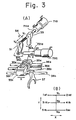
- the rod 711a of the select actuator 710 is actuated to move the internal lever 33 in the direction of the arrow Yl, as illustrated in Fig. 3(A), and the shift lever 31 is turned clockwise about the rod 711a to turn the - internal lever 33 clockwise to move the shift block 35a in the direction of the arrow Xl, thereby selecting the lst gear position.
- the rods 711a, 721a of the select actuator 710 and the shift actuator 720 are arranged perpendicularly to each other, they may be positioned parallel to each other as shown in Fig. 4. More specifically, the rod 711a is separated from a shaft 32 supporting the internal lever 33, and the select and shift actuators 710, 720 are arranged parallel to each other.
- the shaft 32 and the rod 711a are operatively interconnected by a lever 38 mounted on a vertical shaft 38a for angular movement thereabout.
- the lever 38 has ends 38b, 38c pivotably coupled to the shaft 32 and the rod 711a.
- the transmission 6 is equipped with a gear mechanism exactly the same as that of the well-known manual transmission. This is provided with a well-known synchromesh mechanism for performing a synchromesh operation when selecting the lst, 2nd, 3rd, 4th and 5th gear positions for forward motion.
- step 1 in the flowchart the driver removes his foot from the accelerator pedal and shifts the control lever 11 from the drive position D or 1st gear position to the reverse position R (step 1 in the flowchart).
- the electronic control unit 13 which issues a signal to move to execution of the program for controlling.the reversal of the vehicle.
- the electronic control unit 13 produces a clutch disengage signal.
- the switching valves V3, V4 are closed, and simultaneously the directional control valves V5, V8 are switched to the pump P.
- the above valve operation is in preparation for applying the fluid pressure to the chamber 713a in the select actuator 710 and the chamber 723b in the shift actuator 720 when the switching valve Vl is opened, for thereby setting the select and shift actuators 710, 720 into the positions shown in Fig. 2.
- the switching valves Vl, V2 are opened to pressurize the chamber 333a for moving the piston 331 in the clutch actuator 3 to the right (Fig. 2), thus disengaging the clutch 2 (step 2). Since the select and shift actuators 710, 720 are fixed in the positions shown in Fig. 2 by the foregoing operation, they will not be moved in error even though they are acted upon by the fluid pressure from the chamber 333b in the clutch actuator 330.
- the switching valve 2 is closed, and the directional control valves V5, V8 are switched to the tank T.
- the directional control valve V5 is switched to the pump P, and the directional control valves V7, V8 are also switched to the pump P.
- This valve operation fixes the select actuator 710 in the neutral position Nl and causes the shift actuator 720 to shift the internal lever 33 from the lst gear position to the neutral position Nl until the step of the first piston 721 abuts atainst the second piston 722 to stop the rod 721a in the central position (step 3).
- the directional control valves V7, V8 are switched to the pump P to secure the shift actuator 720 in the neutral position Nl, and at the same time the directional control valve V6 is switched to the pump P to pressurize the chamber 713b to force the second piston 712 against the step of the stepped cylinder 713 and the first piston 711 to the lefthand end shown in Fig. 2.
- This position is the neutral position N3 which allows shifting to the 5th gear position or the reverse position Rev (step 4).
- the fluid discharged from the chamber 713a in the select actuator 710 at this time cannot operate the shift actuator 720 in error as the latter is in the fixed position.
- the directional control valve V7 is then switched to the tank T , and the directional control valve V6 is switched to the pump P.
- the directional control valve V 8 is also switched to the pump P (step 5).
- the select actuator 710 is fixed and the shift actuator 720 is actuated to move the internal lever 33 from the neutral postion N3 to the 5th gear position (step 6).
- the synchromesh operates between the main shaft of the transmission 6 and the main drive, so that a force acts upon the idling counter shaft in an effort to stop the counter shaft.
- the disk clutch pressed against the pressure plate or flywheel is separated from the same, and the counter shaft stops rotating.
- the directional control valves V6, V7 are switched to the pump P, and the direction control valve V 8 is switched to the tank T (step 7).
- the select actuator 710 is fixed and the first and second pistons 721, 722 of the shift actuator 720 are moved to the right side in Fig. 2, so that the rod 721a is moved from the 5th gear position to the reverse gear position Rev (step 8).
- the rotation of the counter shaft of the transmission 6 has already been stopped, so that the reverse idle gear also is at rest at this time. Therefore, the main shaft gear can be readily meshed with the reverse idle gear.
- the accelerator pedal 14 is depressed to enable the electronic control unit 13 to issue a command to the clutch control unit 5 for opening and closing the switching valves V3, V4 cyclically to release the fluid pressure in the chamber 333a in the clutch actuator 3 gradually.
- the clutch 2 is forced under its own spring resiliency to move the piston rod 331a slowly to the left (Fig. 2) until the clutch 2 is returned to the engaging or connected position.
- the vehicle now starts moving slowly backward.
- the clutch 2 is fully engaged, the vehicle backs at a speed dependent on the degree of depression of the accelerator pedal 14.
- the switching valve Vl is closed (the switching valve V2 remains closed), and the directional control valves V5, V6, V7, V8 are switched to the tank T while the switching valves V3, V4 remain open, thus releasing the hydraulic pressure.
- step 4 in the flowchart of Fig. 5 the transmission 6 is temporarily switched to the 5th gear position and then to the reverse position Rev. Since this operation comprises movement on one and the same select line, operation solely of the select actuator suffices and the time is used most efficiently.
- the present invention is not limited to this configuration, for it is permissible to switch to a stage provided with another synchromesh mechanism.
- the transmission in the illustrated embodiment has a synchromesh mechanism provided for all of the gear mechanisms from the 1st through 5th gear positions, it goes without saying that the invention is not limited to this arrangement but can be applied to transmissions in which only some of the gear positions are equipped with a synchromesh mechanism.
Abstract
Description
- The present invention relates to a method of electronically controlling a vehicle.
- Vehicles, typically automobiles, powered by internal combustion engines have a transmission coupled between the engine and driven wheels for effective utilization of output power from the engine. In operation, one of different gear ratios of the transmission is selected to meet the particular vehicle speed. For example, when the vehicle is to run at a low speed, a larger gear ratio is used to cause the engine to operate at a high speed.
- In a recently developed transmission system, use is made of a hydraulic drive mechanism controlled by a computerized electronic control unit to automatically drive an internal lever which controls a disk clutch and selects transmission gears. The system has a select actuator for operating the clutch actuator of the hydraulic drive in such a manner that the disk clutch is operated as if by a human foot, and for driving the internal lever selectively in a Y . direction, as well as a shift actuator for driving the internal lever in an X direction perpendicular to the Y direction. The computerized electronic control unit has a memory for storing data known as a shift map representing transmission stages corresponding to automobile speeds and degrees of depression of an accelerator pedal. While the automobile is being driven, the electronic control unit detects the vehicle speed and depression of the accelerator pedal at all times and searches the shift map based on these data to determine an optimum transmission gear. Then, the electronic control unit issues a command to operate the shift actuator and select actuator alternatingly to thereby select an optimum transmission gear ratio.
- Let us investigate an automobile equipped with the electronic control unit in a situation where the automobile is at rest following the completion of forward motion. The engine will be idling, the transmission will be in neutral, and the disk clutch will be in the disengaged state. However, when the transmission is in neutral, the transmission counter shaft is capable of rotating freely so that there are cases where the disk clutch, though disengaged, is still pressed against a pressure plate or flywheel. In consequence, the transmission counter shaft is rotated by the engine. In addition, even if the clutch is completely disengaged immediately after the forwardly traveling automobile is stopped, the counter shaft continues rotating for a time because of inertia. To drive the automobile in reverse starting from the condition of the automobile just described, the driver switches the shift lever to the reverse position, whereupon the electronic control unit issues a command to operate the shift actuator and select actuator alternatingly in an effort to mesh the main shaft gear of the transmission with the reverse idle gear. In this operation, the stationary main shaft gear is made to mesh with the reverse idle gear, which is rotating together with counter shaft, and the disk clutch is made to separate from the pressure plate or flywheel. As a result, the main shaft gear is subjected to an excessive load and, during the shifting operation, not only produces annoying noise but sustains considerable wear. Though this problem can be solved by providing even the reverse position gear mechanism with a synchromesh mechanism, redesigning and manufacturing the.gear mechanism-anew would entail an increase in cost. Another disadvantage is that it would be unable utilize the conventionally employed transmission.
- It is desirable to provide a vehicle electronic control method which enables smooth gear shifting to the reverse position without the provision of a synchromesh mechanism for this purpose.
- The present invention can relate to a vehicle having a clutch controlled by a clutch actuator, a transmission for changing gear ratios by a transmission actuator and having a synchromesh mechanism provided at a gear position other than a reverse gear position, as well as an electronic control unit for controlling both actuators in accordance with the vehicle running conditions. In an embodiment of the present invention a vehicle is controlled electronically through steps including:
- (a) disengaging the clutch in response to a command delivered to a clutch actuator by an electronic control unit at the same time that the transmission starts to be switched to a reverse gear position;
- (b) switching the transmission to a neutral gear position in response to a command delivered to the transmission actuator by the electronic control unit after the clutch is disengaged;
- (c) switching the transmission to a gear position provided- with a sychromesh mechanism in response to a command delivered to the transmission actuator by the electronic control unit with the clutch remaining in the disengaged state; and
- (d) switching the transmission to the reverse gear position in response to a command delivered to the transmission actuator by the electronic control unit with the clutch remaining in the disengaged state.
- Reference will now be made, by way of example, to the accompanying drawings, in which like reference characters designate the same or similar parts throughout the figures thereof, and in which:
- Fig. 1 is a block diagram schematically showing an engine, a transmission, a clutch, and an electronic control unit in a vehicle;
- Fig. 2 is a a circuit diagram of a hydraulic circuit arrangement of a transmission actuator and a clutch actuator;
- Fig. 3(A) is an exploded perspective view illustrative of a portion of the internal construction of the transmission;
- Fig. 3(B) is a top view showing a pattern of movement of an internal lever;
- Fig. 4 is an exploded perspective view of a portion of the internal construction of a transmission according to another embodiment; and
- Fig. 5 is a flowchart showing progressive steps of a gear shifting operation.embodying the invention.
- Fig. 1 schematically shows in block diagram an engine, a transmission, a clutch, and an electronic control unit therefor. A
gasoline engine 1 has a throttle actuator la operatively coupled to a throttle valve lb for actuating the same. Aclutch 2 is operatively connected to the engine and actuatable by aclutch actuator 3 composed of aclutch drive unit 4 and aclutch control unit 5. A parallel-shaft gear transmission 6 is operatively connected to theclutch 2 and actuatable by atransmission actuator 7 for changing gear ratios. The rotation of theengine 1 is detected by anengine rotation sensor 8. Awheel driving mechanism 9 is operatively coupled with thetransmission 6 and includes a propeller shaft, a universal joint, and other components (not shown). Avehicle speed sensor 10 is disposed in thewheel driving mechanism 9. A drive control lever 11 serves to actuate aposition switch 12 which issues a signal to anelectronic control unit 13. In response to the signal from theposition switch 12, theelectronic control unit 13 delivers a signal dependent on the position of the control lever 11 to thetransmission actuator 7 for selecting a gear ratio of thetransmission 6 in accordance with the applied signal. More specifically, when the control lever 11 is in arange 1, thetransmission 6 is controlled to select the 1st gear; when the control lever 11 is in arange 2, thetransmission 6 is controlled to be automatically shifted between the 1st and 2nd gears; when the control lever 11 is in arange 3, thetransmission 6 is controlled to be automatically shifted among lst, 2nd and 3rd gears; when the control lever ll is in arange 4, thetransmission 6 is controlled to be automatically shifted among lst, 2nd, 3rd and 4th gears; when the control lever 11 is in a range D, thetransmission 6 is controlled to be automatically shifted among lst, 2nd, 3rd, 4th and 5th gears; when the control lever 11 is in a range R, thetransmission 6 is controlled to select the reverse gear; and when the control lever 11 is in a range N, thetransmission 6 is controlled to select neutral. The vehicle also has anaccelerator pedal 14, athrottle control unit 15, apotentiometer 16 for detecting the degree of depression of theaccelerator pedal 14, and anidling switch 17. Thethrottle control unit 15 includes a driver 15a for actuating the throttle valve lb and acontroller 15b for controlling the driver 15a. Thethrottle control unit 15 is responsive to a signal from thepotentiometer 16 for controlling the opening of the throttle valve lb dependent on the depression of the.accelerator pedal 14. - The
electronic control unit 13 comprises a read-only memory 13a storing a sequence program for controlling operation of theengine 1, data for controlling gear changes in thetransmission 6, data for controlling actuation of theclutch 2, and other necessary data, a random-access data memory 13b for storing the results of arithmetic operations, input data, and other data, acontrol memory 13c for storing a control program, acentral processor 13d for. executing arithmetic operations and for processing data under the control of the control program and the sequence program, and an input/output interface 13e. According to the present invention, theelectronic control unit 13 controls engine control parameters such as the rate of supply of fuel to thegasoline engine 1 and ignition timing to meet engine operating conditions, and, in addition, controls theclutch 2 and the gear changes in thetransmission 6. For the clutch and transmission control, the read-only memory 13a stores data for connecting and disconnecting theclutch 2 and data for controlling the gear changes in thetransmission 6. - The
electronic control unit 13 receives outputs from thepotentiometer 16, theposition switch 12, and thevehicle speed sensor 10 successively through the input/output interface 13e, these signals entering thedata memory 13b. Thecentral processor 13 computes and determines an optimum gear stage in response to the depression of theaccelerator pedal 14, the indication by the control lever 11 and the speed of the automobile, which are indicated by the received data. The gear change and clutch control data which correspond to the determined gear stage are then read out of the read-only memory 13a and issued through the input/output interface 13e to thetransmission actuator 7 and theclutch actuator 3. Thetransmission actuator 7 and theclutch actuator 3 are then driven in response to the supplied data to operate thetransmission 6 and theclutch 2 for effecting a desired gear change. Theelectronic control unit 13 carries out such data reception, gear stage determination, and issuance of control data at all times so that thetransmission 6 will operate at an optimum gear stage at all times. - Fig. 2 shows a hydraulic circuit arrangement of the
transmission actuator 7 and theclutch actuator 3. The circuit arrangement includes aselect actuator 710, ashift actuator 720, switching valves Vl through V4, directional control valves V5 through V8, a pump P, and a tank T. The lst through 5th gear positions are designated by 1 through 5, the neutral position by N, and the reverse gear position by R. The clutch engaging and disengaging positions are indicated by ON and OFF, respectively. FiG. 3(B) illustrates the gear positions in greater detail, there being three neutral positions Nl, N2 and N3. - The select and
shift actuators stepped cylinders first pistons second pistons first pistons first pistons transmission 6. The select andshift actuators chambers stepped cylinders actuators first pistons second pistons chambers first pistons - The
chambers 713a, 713b in theselect actuator 710 are held in fluid communication through the directional control valves V5, V6, respectively, with the pump P (also through the switching valve Vl) and the tank T. - The
chambers 723a, 723b in theshift actuator 720 are held in fluid communication through the directional control valves V7, V8, respectively, with the pump P (also through the switching valve Vl) and the tank T. - The
clutch actuator 3 comprises acylinder 333, apiston 331 disposed slidably therein, and apiston rod 331a having one end connected to thepiston 331 and an opposite end connected to an actuator lever (not shown) of theclutch 2. Thecylinder 333 has achamber 333a communicating with the pump P through the switching valves Vl, V2 and with the tank T through the switching valve V3 and the switching valve V4 which is controlled to be opened and closed cyclically. Thecylinder 333 also has achamber 333b kept in fluid communication with the tank T at all times. - The
piston 331, thepiston rod 331a, and thecylinder 333 jointly constitute theclutch drive unit 4, and a positional control potentiometer 01 and the switching valves V2, V3, V4 jointly constitute theclutch control unit 5. - As illustrated in Fig. 3(A), the
select actuator 710 and theshift actuator 720 are arranged in a mutually perpendicular Y and X directions, respectively. Theselect actuator 710 includes a rod 711a to which there is secured aninternal lever 33 movable in the Y direction on movement of the rod 7lla in the Y direction. Ashift lever 31 is splined at 34 to the rod 711a at an end thereof for co-rotation therewith, and-is movable in the Y direction along the rod 711a. The rod 711a can be turned about its own axis- in response to angular movement of theshift lever 31. Theshift lever 31 is pivotably joined to the end of therod 721a of theshift actuator 720, which is movable in an X direction perpendicular to the Y direction. Accordingly, when theshift actuator 720 is actuated to move therod 721a axially, theshift lever 31 is angularly moved to turn the rod 711a of theselect actuator 720 about its own axis. Theinternal lever 33' can therefore be moved in the Y direction by the rod 711a, and turned in an SHL direction by theshift lever 31. Theinternal lever 33 has a distal end for engaging,. one at a time,slots shift blocks rods select actuator 710, the end of theinternal lever 33 can traverse theslots 35d - 35f and is positioned in a desired one of theslots 35d - 35f. The angular movement of theshift lever 31 causes one of the shift blocks which is engaged by theinternal lever 33 to move in the X direction. A shift fork 37 (only one shown) is mounted on each of theshift rods internal lever 33 is movable to three positions in the Y direction by axial movement of the rod 711a of theselect actuator 710, and also-to three positions in the X direction by angular movment of theshift lever 31 caused by axial movement of therod 721a of theshift actuator 720. Thus, theinternal lever 33 can assume a total of nine positions. One of theshift blocks internal lever 33 is placed in a corresponding one of the three positions in the Y direction, i.e., select direction. The selected shift block is moved in the X direction or shift direction when theinternal lever 33 is angularly moved to one of the positions in the X direction. The above nine positions correspond to the lst, 2nd, 3rd, 4th, 5th positions, the reverse position Rev, and the neutral positions Nl, N2, N3, as shown in Fig. 3(B), of a manual change lever. Therefore, the select direction is defined as the direction in which theinternal lever 33 can be moved between the neutral positions Nl, N2, N3, and the shift direction is defined as the direction in which theinternal lever 33 is movable from the lst, 2nd, 3rd, 4th, 5th positions and the reverse position Rev to the neutral positions Nl, N2, N3, or vice versa. Theinternal lever 33 is movable along the path defined by two partially overlapping "H"s connecting the nine positions in response to the movement of theshift lever 31 in the X direction and the movement of the rod 711a in the Y direction, and can be stably retained in one of the nine positions at a time. For example, when the 1st gear position is to be selected while theinternal lever 33 is in the neutral position N2, the rod 711a of theselect actuator 710 is actuated to move theinternal lever 33 in the direction of the arrow Yl, as illustrated in Fig. 3(A), and theshift lever 31 is turned clockwise about the rod 711a to turn the -internal lever 33 clockwise to move the shift block 35a in the direction of the arrow Xl, thereby selecting the lst gear position. - Although in Fig. 3(A) the
rods 711a, 721a of theselect actuator 710 and theshift actuator 720 are arranged perpendicularly to each other, they may be positioned parallel to each other as shown in Fig. 4. More specifically, the rod 711a is separated from a shaft 32 supporting theinternal lever 33, and the select and shiftactuators lever 38 mounted on avertical shaft 38a for angular movement thereabout. Thelever 38 hasends actuators - The
transmission 6 is equipped with a gear mechanism exactly the same as that of the well-known manual transmission. This is provided with a well-known synchromesh mechanism for performing a synchromesh operation when selecting the lst, 2nd, 3rd, 4th and 5th gear positions for forward motion. - Reference will now be had to the flowchart of Fig. 5 to describe the operation of the illustrated embodiment for a case where the transmission is shifted from the 1st gear position for forward motion to the reverse position Rev. In Fig. 2, the
internal lever 33 of thetransmission 6 is in the 1st gear position. In this position, the switching valve Vl is closed, the switching valves V2, V3, V4 are open, the directional control valves V5, V6, V7, V8 are in communiation to the tank T which is open to the atmosphere, and no hydraulic pressure acts on theselect actuator 710 and theshift actuator 720. The vehicle is moving forward slowly with theaccelerator pedal 14 depressed slightly. To stop and then back up the vehicle, the driver removes his foot from the accelerator pedal and shifts the control lever 11 from the drive position D or 1st gear position to the reverse position R (step 1 in the flowchart). This is detected by theelectronic control unit 13 which issues a signal to move to execution of the program for controlling.the reversal of the vehicle. With the execution of the program, theelectronic control unit 13 produces a clutch disengage signal. In response to this signal, the switching valves V3, V4 are closed, and simultaneously the directional control valves V5, V8 are switched to the pump P. The above valve operation is in preparation for applying the fluid pressure to the chamber 713a in theselect actuator 710 and thechamber 723b in theshift actuator 720 when the switching valve Vl is opened, for thereby setting the select and shiftactuators chamber 333a for moving thepiston 331 in theclutch actuator 3 to the right (Fig. 2), thus disengaging the clutch 2 (step 2). Since the select and shiftactuators chamber 333b in the clutch actuator 330. When the clutch 2 is disengaged, the switchingvalve 2 is closed, and the directional control valves V5, V8 are switched to the tank T. - Next, the directional control valve V5 is switched to the pump P, and the directional control valves V7, V8 are also switched to the pump P. This valve operation fixes the
select actuator 710 in the neutral position Nl and causes theshift actuator 720 to shift theinternal lever 33 from the lst gear position to the neutral position Nl until the step of thefirst piston 721 abuts atainst thesecond piston 722 to stop therod 721a in the central position (step 3). - When the transmission gears are returned to the neutral position Nl, the directional control valves V5, V7, V8 are switched to the tank.T.
- Thereafter, the directional control valves V7, V8 are switched to the pump P to secure the
shift actuator 720 in the neutral position Nl, and at the same time the directional control valve V6 is switched to the pump P to pressurize thechamber 713b to force thesecond piston 712 against the step of the steppedcylinder 713 and thefirst piston 711 to the lefthand end shown in Fig. 2. This position is the neutral position N3 which allows shifting to the 5th gear position or the reverse position Rev (step 4). The fluid discharged from the chamber 713a in theselect actuator 710 at this time cannot operate theshift actuator 720 in error as the latter is in the fixed position. - Upon completion of the above step, the directional control valves V5, V7, V8 are switched again to the tank T.
- The directional control valve V7 is then switched to the tank T, and the directional control valve V6 is switched to the pump P. The
directional control valve V8 is also switched to the pump P (step 5). In response to this valve operation, theselect actuator 710 is fixed and theshift actuator 720 is actuated to move theinternal lever 33 from the neutral postion N3 to the 5th gear position (step 6). When this gear change is taking place, the synchromesh operates between the main shaft of thetransmission 6 and the main drive, so that a force acts upon the idling counter shaft in an effort to stop the counter shaft. In consequence, the disk clutch pressed against the pressure plate or flywheel is separated from the same, and the counter shaft stops rotating. - Next, the directional control valves V6, V7 are switched to the pump P, and the
direction control valve V8 is switched to the tank T (step 7). As a result of these operations, theselect actuator 710 is fixed and the first andsecond pistons shift actuator 720 are moved to the right side in Fig. 2, so that therod 721a is moved from the 5th gear position to the reverse gear position Rev (step 8). As mentioned above, the rotation of the counter shaft of thetransmission 6 has already been stopped, so that the reverse idle gear also is at rest at this time. Therefore, the main shaft gear can be readily meshed with the reverse idle gear. - When these operations end, the direction control valves V6, V7 are again switched to the tank T, thereby finishing the gear shifting operation from the 1st gear position to the reverse position Rev.
- With the transmission gears in the reverse position Rev, the
accelerator pedal 14 is depressed to enable theelectronic control unit 13 to issue a command to theclutch control unit 5 for opening and closing the switching valves V3, V4 cyclically to release the fluid pressure in thechamber 333a in theclutch actuator 3 gradually. When this is done, theclutch 2 is forced under its own spring resiliency to move thepiston rod 331a slowly to the left (Fig. 2) until theclutch 2 is returned to the engaging or connected position. The vehicle now starts moving slowly backward. When the clutch 2 is fully engaged, the vehicle backs at a speed dependent on the degree of depression of theaccelerator pedal 14. The switching valve Vl is closed (the switching valve V2 remains closed), and the directional control valves V5, V6, V7, V8 are switched to the tank T while the switching valves V3, V4 remain open, thus releasing the hydraulic pressure. - In the illustrated embodiment, after the execution of
step 4 in the flowchart of Fig. 5, thetransmission 6 is temporarily switched to the 5th gear position and then to the reverse position Rev. Since this operation comprises movement on one and the same select line, operation solely of the select actuator suffices and the time is used most efficiently. However, the present invention is not limited to this configuration, for it is permissible to switch to a stage provided with another synchromesh mechanism. - Though the transmission in the illustrated embodiment has a synchromesh mechanism provided for all of the gear mechanisms from the 1st through 5th gear positions, it goes without saying that the invention is not limited to this arrangement but can be applied to transmissions in which only some of the gear positions are equipped with a synchromesh mechanism.
- Although certain preferred embodiments have been shown and described, it should be understood that many changes and modifications may be made therein without departing from the scope of the appended claims.
Claims (4)
Applications Claiming Priority (2)
| Application Number | Priority Date | Filing Date | Title |
|---|---|---|---|
| JP230310/82 | 1982-12-28 | ||
| JP57230310A JPS59120524A (en) | 1982-12-28 | 1982-12-28 | Reverse shift control method of electronically controlled type speed change gear |
Publications (2)
| Publication Number | Publication Date |
|---|---|
| EP0114513A1 true EP0114513A1 (en) | 1984-08-01 |
| EP0114513B1 EP0114513B1 (en) | 1987-08-19 |
Family
ID=16905825
Family Applications (1)
| Application Number | Title | Priority Date | Filing Date |
|---|---|---|---|
| EP83307874A Expired EP0114513B1 (en) | 1982-12-28 | 1983-12-22 | Vehicle electronic control method and mechanism |
Country Status (8)
| Country | Link |
|---|---|
| US (1) | US4601369A (en) |
| EP (1) | EP0114513B1 (en) |
| JP (1) | JPS59120524A (en) |
| KR (1) | KR910000886B1 (en) |
| AU (1) | AU555634B2 (en) |
| CA (1) | CA1202705A (en) |
| DE (1) | DE3373072D1 (en) |
| ES (1) | ES528885A0 (en) |
Cited By (12)
| Publication number | Priority date | Publication date | Assignee | Title |
|---|---|---|---|---|
| EP0193412A2 (en) * | 1985-02-28 | 1986-09-03 | Isuzu Motors Limited | Clutch control system |
| EP0294797A2 (en) * | 1987-06-12 | 1988-12-14 | Diesel Kiki Co., Ltd. | Automatic gear change device |
| EP0310387A2 (en) * | 1987-09-29 | 1989-04-05 | Isuzu Motors Limited | Transmission control apparatus |
| EP0350812A2 (en) * | 1988-07-15 | 1990-01-17 | Attila Dipl.-Ing. Madocsay | Device for automatically shifting a mechanical multi-stage motor vehicle gear selector |
| EP0373273A1 (en) * | 1988-12-16 | 1990-06-20 | Isuzu Motors Limited | Transmission control apparatus |
| WO1993005324A1 (en) * | 1991-08-30 | 1993-03-18 | Zf Friedrichshafen Ag | Change gear with control unit |
| EP0731297A2 (en) * | 1995-03-04 | 1996-09-11 | HYDRAULIK-RING ANTRIEBS- UND STEUERUNGSTECHNIK GmbH | Actuator system for vehicle gear-box |
| FR2750470A1 (en) * | 1996-06-28 | 1998-01-02 | Bosch Gmbh Robert | SYSTEM FOR CONTROLLING A CLUTCH |
| EP0821188A1 (en) * | 1996-07-26 | 1998-01-28 | Agco SA | Forward/reverse gear change system |
| WO2000079152A1 (en) * | 1999-06-21 | 2000-12-28 | Volkswagen Aktiengesellschaft | Method and device for controlling the shifting of gears in an automated transmission of a motor vehicle |
| DE19680781B4 (en) * | 1995-09-12 | 2008-04-30 | Luk Gs Verwaltungs Kg | Control of a torque transmission system for a motor vehicle |
| US10228035B2 (en) | 2016-06-20 | 2019-03-12 | Kongsberg Automotive As | Velocity dependent brake for clutch actuator |
Families Citing this family (25)
| Publication number | Priority date | Publication date | Assignee | Title |
|---|---|---|---|---|
| DE3536935A1 (en) * | 1984-10-27 | 1986-04-30 | Zahnradfabrik Friedrichshafen | CONTROL DEVICE FOR A PRESSURE-OPERATED SWITCHING CLUTCH |
| JPS62122827A (en) * | 1985-11-22 | 1987-06-04 | Isuzu Motors Ltd | Power source device in electronic control device |
| JPH0792138B2 (en) * | 1988-03-01 | 1995-10-09 | 日産自動車株式会社 | Line pressure control device for automatic transmission |
| US4848530A (en) * | 1988-09-06 | 1989-07-18 | Hyster Company | Transmission control providing sequentially engaged high and low speed clutches |
| GB8901605D0 (en) * | 1989-01-25 | 1989-03-15 | Eaton Corp | Emergency device |
| JP3528235B2 (en) * | 1994-05-11 | 2004-05-17 | いすゞ自動車株式会社 | Automatic transmission |
| DE4422427C2 (en) * | 1994-06-28 | 1996-06-05 | Ford Werke Ag | Reverse gear shifting device for a motor vehicle gearbox |
| US5667044A (en) * | 1995-06-07 | 1997-09-16 | Hyundai Motor Company | Transmission device for automobile |
| GB2308874B (en) * | 1995-07-12 | 1999-12-08 | Luk Getriebe Systeme Gmbh | Actuating arrangement |
| DE19601291A1 (en) * | 1996-01-16 | 1997-07-24 | Jochen Dauer Racing Fa | Transmission for vehicle |
| US5638868A (en) * | 1996-06-05 | 1997-06-17 | Valcor Engineering | Accumulator |
| DE19628642C2 (en) * | 1996-07-16 | 1998-09-10 | Ford Global Tech Inc | Electromechanical switching device for change gearboxes of motor vehicles |
| US5979257A (en) * | 1997-12-01 | 1999-11-09 | Chrysler Corporation | Automated manual transmission mode selection controller |
| DE19756943A1 (en) * | 1997-12-22 | 1999-06-24 | Mannesmann Sachs Ag | Actuator for automated actuation of a manual transmission |
| US6470253B1 (en) * | 1998-11-05 | 2002-10-22 | Luk Lamellen Und Kupplungsbau Beteiliguaigs Kg | Vehicle with memory for storing paired values, consisting of first data and the run distance |
| GB9921428D0 (en) * | 1999-09-11 | 1999-11-10 | Luk Getriebe Systeme Gmbh | Automated transmission systems |
| CN101386264B (en) * | 2000-10-20 | 2012-07-04 | 舍弗勒技术股份两合公司 | Motor vehicle with a gearbox and method for operating a motor vehicle |
| JP2002372144A (en) * | 2001-06-15 | 2002-12-26 | Fuji Heavy Ind Ltd | Hydraulic controller for automatic transmission |
| JP3595296B2 (en) * | 2001-11-06 | 2004-12-02 | 本田技研工業株式会社 | Power transmission device |
| DE10230184A1 (en) * | 2002-07-05 | 2004-01-22 | Zf Friedrichshafen Ag | transmission shift |
| EP1380488B1 (en) * | 2002-07-11 | 2008-01-16 | MTD Products Inc. | Vacuum actuated direction and speed control mechanism |
| FR2854221B1 (en) * | 2003-04-23 | 2005-07-22 | Peugeot Citroen Automobiles Sa | PILOTED MANUAL GEARBOX CONTROL DEVICE WITH PRESELECTION GRID AND METHOD FOR CHANGING THE ASSOCIATED RATIO |
| DE102004035365A1 (en) | 2004-07-21 | 2006-02-16 | Deutsche Post Ag | Method and device for sorting mailpieces |
| US8185281B2 (en) * | 2009-06-26 | 2012-05-22 | Bayerische Motoren Werke Aktiengesellschaft | Method and controller for controlling a power train of a vehicle |
| DE102018212694A1 (en) * | 2018-07-30 | 2020-01-30 | Knorr-Bremse Systeme für Nutzfahrzeuge GmbH | Gear shift mechanism |
Citations (4)
| Publication number | Priority date | Publication date | Assignee | Title |
|---|---|---|---|---|
| GB1179838A (en) * | 1967-11-14 | 1970-02-04 | Peugeot | Improvements in or relating to a Gearbox having Synchronizers and at least one Unsynchronized Speed |
| GB1225448A (en) * | 1968-12-12 | 1971-03-17 | ||
| US3756358A (en) * | 1970-07-24 | 1973-09-04 | Bosch Gmbh Robert | Interrelated controls for gearing, clutch, brakes and engine |
| US4324322A (en) * | 1974-04-24 | 1982-04-13 | Sibeud Jean Paul | Method for the automatic control of a gearbox, in particular on a motor vehicle |
Family Cites Families (2)
| Publication number | Priority date | Publication date | Assignee | Title |
|---|---|---|---|---|
| US4181036A (en) * | 1977-05-26 | 1980-01-01 | General Motors Corporation | Stepped-ratio gearing for motor vehicles |
| US4463622A (en) * | 1980-01-11 | 1984-08-07 | Deere & Company | Transmission and reverse gear synchronizing therefor |
-
1982
- 1982-12-28 JP JP57230310A patent/JPS59120524A/en active Granted
-
1983
- 1983-12-21 CA CA000443966A patent/CA1202705A/en not_active Expired
- 1983-12-21 AU AU22717/83A patent/AU555634B2/en not_active Ceased
- 1983-12-22 EP EP83307874A patent/EP0114513B1/en not_active Expired
- 1983-12-22 DE DE8383307874T patent/DE3373072D1/en not_active Expired
- 1983-12-28 ES ES528885A patent/ES528885A0/en active Granted
- 1983-12-28 KR KR1019830006235A patent/KR910000886B1/en not_active IP Right Cessation
- 1983-12-28 US US06/566,324 patent/US4601369A/en not_active Expired - Lifetime
Patent Citations (4)
| Publication number | Priority date | Publication date | Assignee | Title |
|---|---|---|---|---|
| GB1179838A (en) * | 1967-11-14 | 1970-02-04 | Peugeot | Improvements in or relating to a Gearbox having Synchronizers and at least one Unsynchronized Speed |
| GB1225448A (en) * | 1968-12-12 | 1971-03-17 | ||
| US3756358A (en) * | 1970-07-24 | 1973-09-04 | Bosch Gmbh Robert | Interrelated controls for gearing, clutch, brakes and engine |
| US4324322A (en) * | 1974-04-24 | 1982-04-13 | Sibeud Jean Paul | Method for the automatic control of a gearbox, in particular on a motor vehicle |
Cited By (22)
| Publication number | Priority date | Publication date | Assignee | Title |
|---|---|---|---|---|
| EP0193412A2 (en) * | 1985-02-28 | 1986-09-03 | Isuzu Motors Limited | Clutch control system |
| EP0193412A3 (en) * | 1985-02-28 | 1987-09-30 | Isuzu Motors Limited | Clutch control system |
| EP0294797A2 (en) * | 1987-06-12 | 1988-12-14 | Diesel Kiki Co., Ltd. | Automatic gear change device |
| EP0294797A3 (en) * | 1987-06-12 | 1990-05-30 | Diesel Kiki Co., Ltd. | Automatic gear change device |
| EP0310387A2 (en) * | 1987-09-29 | 1989-04-05 | Isuzu Motors Limited | Transmission control apparatus |
| EP0310387A3 (en) * | 1987-09-29 | 1989-09-27 | Isuzu Motors Limited | Transmission control apparatus |
| US4911031A (en) * | 1987-09-29 | 1990-03-27 | Isuzo Motors Limited | Transmission control apparatus |
| EP0350812A2 (en) * | 1988-07-15 | 1990-01-17 | Attila Dipl.-Ing. Madocsay | Device for automatically shifting a mechanical multi-stage motor vehicle gear selector |
| EP0350812A3 (en) * | 1988-07-15 | 1991-03-27 | Attila Dipl.-Ing. Madocsay | Device for automatically shifting a mechanical multi-stage motor vehicle gear selector |
| EP0373273A1 (en) * | 1988-12-16 | 1990-06-20 | Isuzu Motors Limited | Transmission control apparatus |
| WO1993005324A1 (en) * | 1991-08-30 | 1993-03-18 | Zf Friedrichshafen Ag | Change gear with control unit |
| US5488878A (en) * | 1991-08-30 | 1996-02-06 | Zr Friedrichshafen Ag | Gear transmission with controller |
| EP0731297A2 (en) * | 1995-03-04 | 1996-09-11 | HYDRAULIK-RING ANTRIEBS- UND STEUERUNGSTECHNIK GmbH | Actuator system for vehicle gear-box |
| EP0731297A3 (en) * | 1995-03-04 | 1997-07-23 | Hydraulik Ring Gmbh | Actuator system for vehicle gear-box |
| DE19680781B4 (en) * | 1995-09-12 | 2008-04-30 | Luk Gs Verwaltungs Kg | Control of a torque transmission system for a motor vehicle |
| FR2750470A1 (en) * | 1996-06-28 | 1998-01-02 | Bosch Gmbh Robert | SYSTEM FOR CONTROLLING A CLUTCH |
| GB2314895A (en) * | 1996-06-28 | 1998-01-14 | Bosch Gmbh Robert | A system of engaging reverse by controlling a coupling |
| GB2314895B (en) * | 1996-06-28 | 1998-08-19 | Bosch Gmbh Robert | System for engaging reverse by controlling a servo-coupling |
| EP0821188A1 (en) * | 1996-07-26 | 1998-01-28 | Agco SA | Forward/reverse gear change system |
| US5875680A (en) * | 1996-07-26 | 1999-03-02 | Agco Sa | Automatic forward/reverse gear change system having a main clutch disengaged and main vehicle brake engaged during a shuttle shift |
| WO2000079152A1 (en) * | 1999-06-21 | 2000-12-28 | Volkswagen Aktiengesellschaft | Method and device for controlling the shifting of gears in an automated transmission of a motor vehicle |
| US10228035B2 (en) | 2016-06-20 | 2019-03-12 | Kongsberg Automotive As | Velocity dependent brake for clutch actuator |
Also Published As
| Publication number | Publication date |
|---|---|
| EP0114513B1 (en) | 1987-08-19 |
| DE3373072D1 (en) | 1987-09-24 |
| CA1202705A (en) | 1986-04-01 |
| ES8501681A1 (en) | 1984-12-01 |
| KR910000886B1 (en) | 1991-02-12 |
| AU2271783A (en) | 1984-07-05 |
| ES528885A0 (en) | 1984-12-01 |
| AU555634B2 (en) | 1986-10-02 |
| KR840007641A (en) | 1984-12-08 |
| JPS59120524A (en) | 1984-07-12 |
| US4601369A (en) | 1986-07-22 |
| JPS6233097B2 (en) | 1987-07-18 |
Similar Documents
| Publication | Publication Date | Title |
|---|---|---|
| US4601369A (en) | Vehicle electronic control method | |
| US4784007A (en) | Method and apparatus for actuating vehicle transmission | |
| US4638690A (en) | Method and apparatus for controlling electronically controlled transmissions | |
| KR910000473B1 (en) | Transmission shift control system | |
| US4622866A (en) | Transmission and transmission control device for providing downshifting | |
| US4627312A (en) | Automatic transmission | |
| US4850236A (en) | Vehicle drive line shift control system and method | |
| US4194608A (en) | Controls for clutch, motor and transmission | |
| US4674364A (en) | Shift control system of automatic transmission | |
| JP4663840B2 (en) | Engine overrun prevention device for automatic transmission | |
| US5678463A (en) | Process for the global control of a drive unit for a gearbox operated by a hydrostatic system | |
| US3810532A (en) | Automotive transmission with clutch pedal and hydraulic torque converter | |
| JP2648279B2 (en) | Automatic transmission for vehicles | |
| JPH01312254A (en) | Automatic transmission | |
| JPH0533820Y2 (en) | ||
| JP2002144924A (en) | Vehicular automatic transmission | |
| JPH0512507Y2 (en) | ||
| JPS6237557A (en) | Automatic transmission | |
| JPH0443386Y2 (en) | ||
| JPH0512250U (en) | Vehicle automatic transmission | |
| JPS6158695B2 (en) | ||
| JPH0626559A (en) | Power transmission device | |
| JPS6331031B2 (en) | ||
| JPH0519235Y2 (en) | ||
| JPH0550628B2 (en) |
Legal Events
| Date | Code | Title | Description |
|---|---|---|---|
| PUAI | Public reference made under article 153(3) epc to a published international application that has entered the european phase |
Free format text: ORIGINAL CODE: 0009012 |
|
| AK | Designated contracting states |
Designated state(s): CH DE FR GB IT LI SE |
|
| 17P | Request for examination filed |
Effective date: 19841221 |
|
| 17Q | First examination report despatched |
Effective date: 19860120 |
|
| GRAA | (expected) grant |
Free format text: ORIGINAL CODE: 0009210 |
|
| AK | Designated contracting states |
Kind code of ref document: B1 Designated state(s): CH DE FR GB IT LI SE |
|
| ITF | It: translation for a ep patent filed |
Owner name: ING. ZINI MARANESI & C. S.R.L. |
|
| REF | Corresponds to: |
Ref document number: 3373072 Country of ref document: DE Date of ref document: 19870924 |
|
| ET | Fr: translation filed | ||
| PLBE | No opposition filed within time limit |
Free format text: ORIGINAL CODE: 0009261 |
|
| STAA | Information on the status of an ep patent application or granted ep patent |
Free format text: STATUS: NO OPPOSITION FILED WITHIN TIME LIMIT |
|
| 26N | No opposition filed | ||
| ITTA | It: last paid annual fee | ||
| PGFP | Annual fee paid to national office [announced via postgrant information from national office to epo] |
Ref country code: FR Payment date: 19941027 Year of fee payment: 12 |
|
| EAL | Se: european patent in force in sweden |
Ref document number: 83307874.4 |
|
| PGFP | Annual fee paid to national office [announced via postgrant information from national office to epo] |
Ref country code: CH Payment date: 19950327 Year of fee payment: 12 |
|
| PG25 | Lapsed in a contracting state [announced via postgrant information from national office to epo] |
Ref country code: LI Effective date: 19951231 Ref country code: CH Effective date: 19951231 |
|
| REG | Reference to a national code |
Ref country code: CH Ref legal event code: PL |
|
| PG25 | Lapsed in a contracting state [announced via postgrant information from national office to epo] |
Ref country code: FR Effective date: 19960830 |
|
| REG | Reference to a national code |
Ref country code: FR Ref legal event code: ST |
|
| PGFP | Annual fee paid to national office [announced via postgrant information from national office to epo] |
Ref country code: GB Payment date: 19971215 Year of fee payment: 15 |
|
| PGFP | Annual fee paid to national office [announced via postgrant information from national office to epo] |
Ref country code: SE Payment date: 19971218 Year of fee payment: 15 |
|
| PG25 | Lapsed in a contracting state [announced via postgrant information from national office to epo] |
Ref country code: GB Free format text: LAPSE BECAUSE OF NON-PAYMENT OF DUE FEES Effective date: 19981222 |
|
| PG25 | Lapsed in a contracting state [announced via postgrant information from national office to epo] |
Ref country code: SE Free format text: LAPSE BECAUSE OF NON-PAYMENT OF DUE FEES Effective date: 19981223 |
|
| GBPC | Gb: european patent ceased through non-payment of renewal fee |
Effective date: 19981222 |
|
| PGFP | Annual fee paid to national office [announced via postgrant information from national office to epo] |
Ref country code: DE Payment date: 20001122 Year of fee payment: 18 |
|
| PG25 | Lapsed in a contracting state [announced via postgrant information from national office to epo] |
Ref country code: DE Free format text: LAPSE BECAUSE OF NON-PAYMENT OF DUE FEES Effective date: 20020702 |