EP0114378A2 - Fuel injection apparatus for internal combustion engine - Google Patents
Fuel injection apparatus for internal combustion engine Download PDFInfo
- Publication number
- EP0114378A2 EP0114378A2 EP83112967A EP83112967A EP0114378A2 EP 0114378 A2 EP0114378 A2 EP 0114378A2 EP 83112967 A EP83112967 A EP 83112967A EP 83112967 A EP83112967 A EP 83112967A EP 0114378 A2 EP0114378 A2 EP 0114378A2
- Authority
- EP
- European Patent Office
- Prior art keywords
- fuel injection
- counting
- control valve
- internal combustion
- injection device
- Prior art date
- Legal status (The legal status is an assumption and is not a legal conclusion. Google has not performed a legal analysis and makes no representation as to the accuracy of the status listed.)
- Granted
Links
Images


Classifications
-
- F—MECHANICAL ENGINEERING; LIGHTING; HEATING; WEAPONS; BLASTING
- F02—COMBUSTION ENGINES; HOT-GAS OR COMBUSTION-PRODUCT ENGINE PLANTS
- F02D—CONTROLLING COMBUSTION ENGINES
- F02D41/00—Electrical control of supply of combustible mixture or its constituents
- F02D41/30—Controlling fuel injection
- F02D41/3005—Details not otherwise provided for
-
- F—MECHANICAL ENGINEERING; LIGHTING; HEATING; WEAPONS; BLASTING
- F02—COMBUSTION ENGINES; HOT-GAS OR COMBUSTION-PRODUCT ENGINE PLANTS
- F02D—CONTROLLING COMBUSTION ENGINES
- F02D41/00—Electrical control of supply of combustible mixture or its constituents
- F02D41/30—Controlling fuel injection
- F02D41/32—Controlling fuel injection of the low pressure type
- F02D41/34—Controlling fuel injection of the low pressure type with means for controlling injection timing or duration
- F02D41/345—Controlling injection timing
-
- F—MECHANICAL ENGINEERING; LIGHTING; HEATING; WEAPONS; BLASTING
- F02—COMBUSTION ENGINES; HOT-GAS OR COMBUSTION-PRODUCT ENGINE PLANTS
- F02D—CONTROLLING COMBUSTION ENGINES
- F02D41/00—Electrical control of supply of combustible mixture or its constituents
- F02D41/30—Controlling fuel injection
- F02D41/38—Controlling fuel injection of the high pressure type
- F02D41/40—Controlling fuel injection of the high pressure type with means for controlling injection timing or duration
- F02D41/401—Controlling injection timing
-
- F—MECHANICAL ENGINEERING; LIGHTING; HEATING; WEAPONS; BLASTING
- F02—COMBUSTION ENGINES; HOT-GAS OR COMBUSTION-PRODUCT ENGINE PLANTS
- F02B—INTERNAL-COMBUSTION PISTON ENGINES; COMBUSTION ENGINES IN GENERAL
- F02B3/00—Engines characterised by air compression and subsequent fuel addition
- F02B3/06—Engines characterised by air compression and subsequent fuel addition with compression ignition
-
- F—MECHANICAL ENGINEERING; LIGHTING; HEATING; WEAPONS; BLASTING
- F02—COMBUSTION ENGINES; HOT-GAS OR COMBUSTION-PRODUCT ENGINE PLANTS
- F02D—CONTROLLING COMBUSTION ENGINES
- F02D41/00—Electrical control of supply of combustible mixture or its constituents
- F02D41/20—Output circuits, e.g. for controlling currents in command coils
- F02D2041/202—Output circuits, e.g. for controlling currents in command coils characterised by the control of the circuit
- F02D2041/2031—Control of the current by means of delays or monostable multivibrators
-
- F—MECHANICAL ENGINEERING; LIGHTING; HEATING; WEAPONS; BLASTING
- F02—COMBUSTION ENGINES; HOT-GAS OR COMBUSTION-PRODUCT ENGINE PLANTS
- F02D—CONTROLLING COMBUSTION ENGINES
- F02D41/00—Electrical control of supply of combustible mixture or its constituents
- F02D41/30—Controlling fuel injection
- F02D41/38—Controlling fuel injection of the high pressure type
- F02D41/40—Controlling fuel injection of the high pressure type with means for controlling injection timing or duration
- F02D41/406—Electrically controlling a diesel injection pump
- F02D41/407—Electrically controlling a diesel injection pump of the in-line type
-
- Y—GENERAL TAGGING OF NEW TECHNOLOGICAL DEVELOPMENTS; GENERAL TAGGING OF CROSS-SECTIONAL TECHNOLOGIES SPANNING OVER SEVERAL SECTIONS OF THE IPC; TECHNICAL SUBJECTS COVERED BY FORMER USPC CROSS-REFERENCE ART COLLECTIONS [XRACs] AND DIGESTS
- Y02—TECHNOLOGIES OR APPLICATIONS FOR MITIGATION OR ADAPTATION AGAINST CLIMATE CHANGE
- Y02T—CLIMATE CHANGE MITIGATION TECHNOLOGIES RELATED TO TRANSPORTATION
- Y02T10/00—Road transport of goods or passengers
- Y02T10/10—Internal combustion engine [ICE] based vehicles
- Y02T10/40—Engine management systems
Definitions
- the invention relates to a fuel injection device for air-compressing, self-igniting reciprocating internal combustion engines with a fuel injection pump and with an injection nozzle per cylinder unit, wherein at least one variable that characterizes the injection process, such as injection start, injection end or injection duration, can be regulated by at least one electromagnetic control valve per cylinder unit, which is preferably one on the High-pressure side of the fuel injection pump provided low pressure channel, in particular an outflow channel, controlled and controlled by an electrically working measured value processing device depending on characteristic influencing variables of the internal combustion engine by means of a control pulse, and where appropriate, a further, mechanically actuated actuator for controlling the fuel injection device is provided.
- Such a generic fuel injection device with an electromagnetic control valve and a measured value processing device is known from DE-OS 20 26-665 known.
- An electromagnetic control valve is provided for each cylinder unit, which controls an outflow channel on the pressure side of the fuel injection pump, which can be released by the control valve, in particular for regulating the injection end of the fuel injection device.
- control valve is assigned a delay device which, taking into account the control valve-specific transmission behavior, transmits the control pulse of the measured value processing device to the electromagnetic control valve in such a way that the control valve opens and / or closes with a constant delay time during each actuation process constant delay time of the control valve depending on the actual speed of the internal combustion engine can be represented and that the triggering time of the control valve determined by the measured value processing device can be changed in the opening and / or closing direction depending on the constant time delay of the control valve.
- the constant delay time is advantageously designed in such a way that the magnetic, electrical and mechanical error influences on the transmission behavior of the electromagnetic control valves are comprehensively taken into account, so that it is advantageously possible to use a suitable circuit to control the transmission valve-specific transmission behavior of each electromagnetic control valve to apply the constant delay same and to determine the constant time delay with a central electrical device as a function of the speed of the internal combustion engine and to take this into account when controlling the electromagnetic control valves by the electrically working measured value processing device.
- the delay device preferably comprises a first delay element with a constant delay time, a second delay element with a variable delay time, a circuit breaker, a device for detecting the armature movement of the control valve with a conditioning unit and a phase discriminator.
- a constant delay time of 2.56 ms is sufficient, which furthermore also has the further advantage that the constant delay time of 2.56 ms can be easily achieved with electrical components.
- the valve-specific transmission behavior is preferably matched to the constant time delay via the phase discriminator, which compares the actual value supplied by the device for detecting the armature movement of the control valve with the setpoint value supplied by the measurement processing device and constantly delayed by the first delay element, and the second delay element by means of a correction control variable Preferred.that regulates that the setpoint and the actual value are coincident on the phase discriminator.
- the reciprocating internal combustion engine 1 comprises six serially arranged Z-y-relieving units 2, a flywheel 3, a gear box 4, and an injection pump 5 in block design on.
- the injection pump 5 is - not shown in detail - connected in a known manner on the drive side to the wheel housing 4 and delivers fuel to the injection nozzles 6, the fuel being supplied to the injection pump 5 from a fuel tank (not shown) via a fuel delivery pump.
- an electromagnetic control valve 7 is provided for each cylinder unit 2, each of which controls an outflow channel (not shown).
- a central control device 8 which contains an electrically working measured value processing device, not shown, which interacts with suitable transmitters, not shown, and controls the electromagnetic control valves 7 by means of control pulses as a function of characteristic influencing variables of the reciprocating piston internal combustion engine 1, for example temperature, speed, etc.
- the electromagnetic control valves due to operating and wear-related transmission errors on the data generated by the electrical measurement processing control pulses delayed valve is specific, according to the invention provided within the central control unit 8 for each electromagnetic control valve 7, a delay means for taking account of the control valve specific Ubertragungs s of the control pulses of the measurement processing on such the respective electromagnetic control valve 7 transmits that each electromagnetic control valve 7, each Z ylin- derech 2 at each driving operation with a constant delay time, for example 2.56 ms opens and closes.
- 3 angular pulse generator elements 9 with a 1 ° angle division are arranged on the flywheel a sensor device 10 generate pulse sequences dependent on the actual speed of the reciprocating piston internal combustion engine 1, which are used in a suitable circuit also provided in the central control unit 8, which will be discussed in more detail below, to represent the constant delay time as a function of the actual speed of the reciprocating piston internal combustion engine 1.
- the angular pulse generator element arrangement 9 comprises, not shown in more detail, a synchronous pulse generator element which generates a synchronizing pulse which characterizes the start of the working cycle of the reciprocating piston internal combustion engine 1 in the sensor device 10 and which can be evaluated in a circuit of the central control device 8 and the internal dead center I (FIG. 5) which in FIG the firing order first cylinder unit 2 of a working cycle of the Hubkol - associated benbrennkraftmaschine. 1
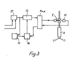
- a delay device of an electromagnetic control valve 7 according to the invention is shown in FIG. 3.
- the delay device according to the invention has a first delay element 12 with a constant delay time, which is preferably 2.56 ms, a second delay element 13 with a variable delay time, a circuit breaker 14a, a device 15 with a conditioning unit 14b for detecting the armature movement of the control valve 7, which for example consists of can consist of a permanent magnet, an induction coil and associated pole pieces and in a manner known per se generates control signals due to the change in a magnetic resistance, for example, and a phase discriminator 16.
- the control pulse of the measured value processing device which is adjusted according to the invention to the constant delay time as a function of the speed by the circuit arrangement shown in FIG.
- phase discriminator 16 is supplied via a bistable flip-flop 17 on the one hand to the first delay element 12 and on the other hand to the second delay element 13. After a constant delay time of 2.56 ms, the delay element 12 supplies an output signal to the phase discriminator 16. Via the second delay element 13 and the circuit breaker 14a, the control pulse of the measured value processing device is fed to the electromagnetic control valve 7. After a valve-specific delay time, the control valve 7 reacts to the control pulse of the measured value processing device, the armature movement of the electromagnetic valve 7 in the device 14 generating an output signal which can be supplied as an actual value to the phase discriminator 16 via the processing unit 14b.
- the phase discriminator 16 which will be explained in more detail in connection with the description of FIG.
- a circuit which represents the constant delay time of the electromagnetic control valve 7 as a function of the actual speed of the internal combustion engine and the triggering time of the control valve in the opening and / or closing direction determined by the electrically working measured value processing device as a function of the constant delay time of the control valve changed.
- 18 denotes a frequency multiplier, to which the pulse trains determined by the sensor device 10 (FIG. 1) are fed via the line 11.
- the pulse sequences are on the one hand twenty times, which are thus supplied as 0.05 ° crankshaft angle range pulses via a line 19 to an AND gate 20, and on the other hand ten times, which are thus as 0.1 1 crankshaft angle range pulses on an OR gate 21 can be supplied via a line 22 and a sequence controller 23 via a line 24.
- the sequencer 23 is also connected to a switching stage 26 via the line 250.
- the AND gate 20 is controlled via a line 25 by the switching stage 26 provided with a timer, the timer of the switching stage 26 being matched to the constant delay time of the first delay element 12 (FIG. 3) and to the different frequency multiplication within the frequency multiplier 18 .
- the timer is designed for half the constant delay time of 1.28 ms.
- the 0.05 ° crankshaft angle range pulses are fed via a line 27 to a first counting device 28, which continuously determines the o, o5 ° pulses during the switch-on time of 1.28 ms.
- the output of the first counter 28 is a 10-bit data line 29, a memory 30 and a comparator 32 connected via a further 10-bit data line 31.
- the first counting device 28 has an 8-bit input 33 at which a setpoint for the start of injection changes determined by the electrically working measured value processing device is applied.
- an output 34 of sequence controller 23, with 0.1 ° on the line 24 - K urbelwellenwinkel Gebsimpulsen is synchronized by the frequency multiplier 18, connected to the first counting means 28 and via an output 35 to the memory 30th
- a gate circuit 38 is assigned to the comparator 32 via connections 36 and 37, to which an input signal 39 of the sequence controller 23 is also present.
- the gate circuit 38 is connected via a line 40 to a second counting device 41 and via a line 42 to the OR gate 21.
- the second counting device 41 is connected via line 43 to the OR gate 21 and thus to the frequency multiplier 18 and via a 10-bit data line 44 to the memory 30 and continuously determines 0.1 ° crankshaft angle pulse counting intervals by a predeterminable maximum value are limited.
- the synchronous control signal generated by the synchronous mark on the flywheel 3 in the sensor device 10 is also present on the input side via lines 45, 46.
- the 0.05 ° crankshaft angle pulses are counted.
- the measured variable of the next count and the memory content are compared in the comparator 32, and the content of the memory 30 is subjected to a corresponding correction pulse via the connection to the comparator 32 and the line 35, depending on the comparison result, due to the very fast counting rhythm the comparison difference applied to the comparator is a maximum of 1 crankshaft angle pulse and the correction pulse is set in the gap between two 0.1 ° crankshaft angle pulses via the sequence control 23.
- the correction via the comparator 32 and the gate circuit 38 is carried out continuously.
- the memory 30 is set to the current measured variable of the counting device 28 by the synchronizing pulse which is produced in the sensor device 10 and transmitted via the line 47.
- the second counting device counts in parallel to the first counting device 28 the 0.1 ° crankshaft angle pulses generated by the frequency multiplier 18 in continuous counting intervals, which in the present six-cylinder internal combustion engine 1 are limited by the predetermined maximum value of 1,200 counting pulses corresponding to a 120 ° ignition angle range. If at the input 46 of the second counting device 41 the sync pulse signal characterizing the start of the working cycle of the internal combustion engine 1 is present, the content of the memory 30 is set in the second counting device 41 via the 10-bit data line 44, so that the second counting device 41 Fixed predetermined value of 120 ° crankshaft angle range reached earlier accordingly.
- the correction pulses characterizing the changes in the actual speed of internal combustion engine 1 are also fed via gate circuit 38 and OR gate 21 to second counting device 41, with sequence controller 23 ensuring that these correction pulses into the gap between two 0.1 ° - crankshaft angle pulses are set.
- the counting device 41 is given whether the respective correction pulse is added to or subtracted from the counter reading.
- the second counting device 41 generates a control pulse for the start of injection, which is fed to a decoder 49.
- the decoder 49 transmits the start of injection pulse to the bistable flip-flops 17 of the individual delay devices of the electromagnetic control valves 7 of the cylinder units 2 via outputs 491, 492, 493, 494, 495, 496.
- a third counting device 51 is connected via a line 50 to the output 48 of the second counting device 41 and via a line 52 to the output 24 of the frequency multiplier 18, so that the third counting device also counts the 0.1 ° crankshaft angle pulses generated by the frequency multiplier 18 .
- a digital comparison device 53 is provided on the third counting device 51 and is connected to the electrical measured value processing device via an 8-bit input 54.
- the comparison device 53 If the target quantity entered by the third counting device 51 for the spray duration reaches the comparison device 53, the comparison device 53 generates a control pulse for the spray end, which is fed via an output 55 to a second decoder 56, which switches the flip-flops 17 of the individual delay devices controls the respective electromagnetic control valves 7 of the cylinder units 2 in the closing direction via lines 561, 562, 563, 564, 565, 566, the decoder 49 for the start of spraying and the decoder 56 for the end of spraying being controlled by a cylinder counter 57 which is connected via an input 58 is synchronized by the synchronizing pulse generated in the sensor device 10 (FIG. 1). The cylinder counter 57 is connected via a line 59 to the third counting device 51 and is continued by a corresponding switching pulse after the control pulse of the comparison device 53.
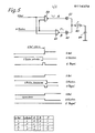
- the phase discriminator 16 (FIG. 3) of the individual delay devices of the control valves 7 is explained in more detail.
- the control signals U Ref transmitted by the first delay device 12 and the feedback signals U remindm generated by the device 15 for detecting the armature movement of the electromagnetic control valve 7 are respectively on the input side of a NAND link 59 and a NOR link 60. Due to the positive edges of URef and the negative edges of URückm, "high impulses" are generated at outputs A and B when the feedback signal arrives before the constant delay time expires (in the present case 2.56 ms) and when the feedback signal arrives after the constant delay time "low pulses" formed. The temporal width of the pulses is influenced by the time difference between the two input signals.
- the pulses are fed to a capacitor 64 which, depending on the direction ("high” or “low”) and pulse width (duration), forms a charging voltage.
- This charging voltage regulates the second delay element 13 with the variable delay time as a control variable.
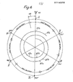
- FIG. 6 shows a flowchart of an operating cycle of the reciprocating piston internal combustion engine 1, with I to VI denoting the inner dead centers of the cylinder units 2 in the firing sequence 1-5-3-6-2-4 as a function of the crankshaft angle, each having an ignition interval of 120 ° crankshaft angle.
- the 1.28 ms turn-on times of the first counting device 28 for determining the 0.55 crankshaft angle pulses and 65b indicate the time intervals in which the memory 30 and the second counting device 41 are indicated by the comparator 32 and the gate circuit 38 are corrected in accordance with the actual speed of the reciprocating piston internal combustion engine 1 determined by the first counting device 28, and the correction pulses are set by the sequence controller 23 into the gap between two successive 0.1 ° crankshaft angle pulses.
- the maximum value that limits the counting intervals of the second counting device 41 is set at 1200 in accordance with the ignition interval.
- the crankshaft angle range is identified by 66, which corresponds to the constant deceleration time of the deceleration device of 2.56 ms at a predetermined actual engine speed and was determined by the first counting device 28 and can be set in the second counter 41 via the synchronizing pulse.
- a setpoint for the start of injection determined by the electrical measured value processing device is also taken into account, so that when the maximum value of the second counting device triggering the start of injection control pulse is reached, the electromagnetic control valve 7 opens exactly, changes in the actual speed of the reciprocating piston internal combustion engine 1 during the working stroke of the reciprocating piston internal combustion engine by means of the Correction impulses caused positive or negative correction is taken into account.
Abstract
Description
Die Erfindung bezieht sich auf eine Kraftstoffeinspritzvorrichtung für luftverdichtende, selbstzündende Hubkolbenbrennkraftmaschinen mit einer Kraftstoffeinspritzpumpe und mit einer Einspritzdüse je Zylindereinheit wobei zumindest eine den Einspritzvorgang kennzeichnende Größe wie Einspritzbeginn, Einspritzende bzw. Einspritzdauer durch zumindest ein elektromagnetisches Steuerventil je Zylindereinheit regelbar ist, das vorzugsweise einen auf der Hochdruckseite der Kraftstoffeinspritzpumpe vorgesehenen Niederdruckkanal, insbesondere einen Abströmkanal, beherrscht und von einer elektrisch arbeitenden Meßwertverarbeitungseinrichtung in Abhängigkeit von charakteristischen Einflußgrößen der Brennkraftmaschine mittels eines Steuerimpulses ansteuerbar ist, und wobei gegebenenfalls ein weiteres, mechanisch betätigbares Stellglied zur Steuerung der Kraftstoffeinspritzvorrichtung vorgesehen ist.The invention relates to a fuel injection device for air-compressing, self-igniting reciprocating internal combustion engines with a fuel injection pump and with an injection nozzle per cylinder unit, wherein at least one variable that characterizes the injection process, such as injection start, injection end or injection duration, can be regulated by at least one electromagnetic control valve per cylinder unit, which is preferably one on the High-pressure side of the fuel injection pump provided low pressure channel, in particular an outflow channel, controlled and controlled by an electrically working measured value processing device depending on characteristic influencing variables of the internal combustion engine by means of a control pulse, and where appropriate, a further, mechanically actuated actuator for controlling the fuel injection device is provided.
Eine derart gattungsgemäße Kraftstoffeinspritzvorrichtung mit einem elektromagnetischen Steuerventil und einer Meßwertverarbeitungseinrichtung ist aus der DE-OS 20 26--665 bekannt. Hierbei ist je Zylindereinheit ein elektromagnetisches Steuerventil vorgesehen, das auf der Druckseite der Kraftstoffeinspritzpumpe einen Abströmkanal beherrscht, der durch das Steuerventil insbesondere zur Regelung des Einspritzendes der Kraftstoffeinspritzvorrichtung freigebbar ist. Um bei einer derartigen Kraftstoffeinspritzvorrichtung das verschleiß- und betriebsbedingte Streuungen des Ubertragungsverhaltens der elektromagnetischen Steuerventile ausgleichen zu können, wird in der DE-OS 20 26 665 vorgeschlagen, die Istwertsteuerzeiten eines einzigen elektromagnetischen Steuerventils zu ermitteln und die übrigen elektromagnetischen Steuerventile unter Berücksichtigung des Vergleiches der Istwertsteuerzeiten dieses elektromagnetischen Steuerventils und der Sollwertsteuerzeiten der elektrisch arbeitenden Meßwertverarbeitungseinrichtung anzusteuern. Da das Ubertragungsverhalten der elektromagnetischen Steuerventile jedoch aufgrund spezifischer Verschleißerscheinungen sehr unterschiedlich sein kann, können mit einer derartigen Vorrichtung Streuungen aller elektromagnetischen Steuerventile der Zylindereinheiten der Brennkraftmaschine nur sehr unzureichend ausgeglichen werden, so daß ein einwandfreier Betrieb einer luftverdichtenden, selbstzündenden Hubkolbenbrennkraftmaschine mit einer derartigen Kraftstoffeinspritzvorrichtung insbesondere im Hinblick auf die im zunehmendem-Maße angestrebten sehr hohen Kraftstoffeinspritzdrücke und der dementsprechend sehr kurzen Einspritzdauer nicht möglich ist.Such a generic fuel injection device with an electromagnetic control valve and a measured value processing device is known from DE-OS 20 26-665 known. An electromagnetic control valve is provided for each cylinder unit, which controls an outflow channel on the pressure side of the fuel injection pump, which can be released by the control valve, in particular for regulating the injection end of the fuel injection device. In order to be able to compensate for the wear and operational scatter of the transmission behavior of the electromagnetic control valves in such a fuel injection device, it is proposed in DE-OS 20 26 665 to determine the actual value control times of a single electromagnetic control valve and the other electromagnetic control valves taking into account the comparison of the actual value control times this electromagnetic control valve and the setpoint control times of the electrically working measured value processing device. However, since the transmission behavior of the electromagnetic control valves can be very different due to specific signs of wear, scattering of all the electromagnetic control valves of the cylinder units of the internal combustion engine can be compensated for only inadequately with such a device, so that proper operation of an air-compressing, self-igniting reciprocating piston internal combustion engine with such a fuel injection device, in particular in the In view of the increasingly high desired fuel injection pressures and the correspondingly very short injection duration is not possible.
Es ist daher Aufgabe der vorliegenden Erfindung, eine gattungsgemäße Kraftstoffeinspritzvorrichtung der eingangs genannten Art dahingehend zu verbessern, daß Streuungen des Übertragungsverhaltens der elektromagnetischen Steuerventile der Kraftstoffeinspritzvorrichtung ausgleichbar ist und die von der elektrisch arbeitenden Meßwertverarbeitungseinrichtung ermittelten Steuerzeitpunkte der elektromagnetischen Steuerventile exakt und genau einstellbar sind.It is therefore an object of the present invention to improve a generic fuel injection device of the type mentioned in the introduction such that variations in the transmission behavior of the electromagnetic control valves of the fuel injection device can be compensated for is and the control times of the electromagnetic control valves determined by the electrically working measured value processing device can be set exactly and precisely.
Diese Aufgabe wird erfindungsgemäß dadurch gelöst, daß dem Steuerventil eine Verzögerungseinrichtung zugeordnet ist, die unter Berücksichtigung des steuerventilspezifischen Ubertragungsverhaltens den Steuerimpuls der Meßwertverarbeitungseinrichtung derart auf das elektromagnetische Steuerventil überträgt, daß das Steuerventil bei jedem Ansteuervorgang mit einer konstanten Verzögerungszeit öffnet und/oder schließt, daß die konstante Verzögerungszeit des Steuerventils in Abhängigkeit der Istdrehzahl der Brennkraftmaschine darstellbar ist und daß der von der Meßwertverarbeitungseinrichtung ermittelte Ansteuerzeitpunkt des Steuerventils im öffnungs- und/oder Schließsinn in Abhängigkeit der konstanten Zeitverzögerung des Steuerventils veränderbar ist.This object is achieved in that the control valve is assigned a delay device which, taking into account the control valve-specific transmission behavior, transmits the control pulse of the measured value processing device to the electromagnetic control valve in such a way that the control valve opens and / or closes with a constant delay time during each actuation process constant delay time of the control valve depending on the actual speed of the internal combustion engine can be represented and that the triggering time of the control valve determined by the measured value processing device can be changed in the opening and / or closing direction depending on the constant time delay of the control valve.
Durch diese Merkmale ist es in vorteilhafter Weise möglich, Streuungen bzw. ein unterschiedliches Ubertragungsverhalten der elektromagnetischen Steuerventile auf einfache Weise und unabhängig voneinander auszugleichen. Die konstante Verzögerungszeit ist dabei in vorteilhafter Weise derart ausgelegt, daß die magnetischen, elektrischen und mechanischen Fehlereinflüsse auf das Ubertragungsverhalten der elektromagnetischen Steuerventile umfassend berücksichtigt sind, so daß es in vorteilhafter Weise möglich ist, über eine geeignete Schaltung das steuerventilspezifische Ubertragungsverhalten eines jeden elektromagnetischen Steuerventils an die konstante Verzögerung anzu gleichen und die konstante Zeitverzögerung mit einer zentralen elektrischen Einrichtung in Abhängigkeit der Drehzahl der Brennkraftmaschine zu ermitteln und bei der Ansteuerung der elektromagnetischen Steuerventile durch die elektrisch arbeitende Meßwertverarbeitungseinrichtung zu berücksichtigen. Bevorzugt umfaßt die Verzögerungseinrichtung ein erstes Verzögerungsglied mit konstanter Verzögerungszeit, ein zweites Verzögerungsglied mit veränderbarer verzögerungszeit, einen Leistungsschalter, eine Einrichtung zum Erkennen der Ankerbewegung des Steuerventils mit einer Aufbereitungseinheit und einen Phasendiskriminator. Hierbei hat es sich in vielen Anwendungsfällen eine konstante Verzögerungszeit von 2,56 ms als ausreichend herausgestellt, was ferner auch noch den weiteren Vorteil beinhaltet, daß die konstante Verzögerungszeit von 2,56 ms mit elektrischen Bauteilen einfach verwirklicht werden kann. Die Angleichung des ventilspezifischen Ubertragungsverhaltens an die konstante Zeitverzögerung erfolgt bevorzugt über den Phasendiskriminator, der den durch die Einrichtung zum Erkennen der Ankerbewegung des Steuerventils gelieferten Istwert mit dem von der MeBwertverarbeitungseinrichtung gelieferten und durch das erste Verzögerungsglied konstant verzögerten Sollwert vergleicht und das zweite Verzögerungsglied durch eine Korrektursteuergröße bevorzugt.derart regelt, daß der Sollwert und der Istwert koinzident am Phasendiskriminator vorliegen.These features advantageously make it possible to easily and independently compensate for scatter or a different transmission behavior of the electromagnetic control valves. The constant delay time is advantageously designed in such a way that the magnetic, electrical and mechanical error influences on the transmission behavior of the electromagnetic control valves are comprehensively taken into account, so that it is advantageously possible to use a suitable circuit to control the transmission valve-specific transmission behavior of each electromagnetic control valve to apply the constant delay same and to determine the constant time delay with a central electrical device as a function of the speed of the internal combustion engine and to take this into account when controlling the electromagnetic control valves by the electrically working measured value processing device. The delay device preferably comprises a first delay element with a constant delay time, a second delay element with a variable delay time, a circuit breaker, a device for detecting the armature movement of the control valve with a conditioning unit and a phase discriminator. In many applications, it has been found that a constant delay time of 2.56 ms is sufficient, which furthermore also has the further advantage that the constant delay time of 2.56 ms can be easily achieved with electrical components. The valve-specific transmission behavior is preferably matched to the constant time delay via the phase discriminator, which compares the actual value supplied by the device for detecting the armature movement of the control valve with the setpoint value supplied by the measurement processing device and constantly delayed by the first delay element, and the second delay element by means of a correction control variable Preferred.that regulates that the setpoint and the actual value are coincident on the phase discriminator.
Weitere vorteilhafte Ausgestaltungen der Erfindung, insbesondere zur Darstellung der konstanten Verzögerungszeit in Abhängigkeit der Drehzahl der Brennkraftmaschine und der schaltungstechnischen Veränderung des Ansteuerzeitpunktes des elektromagnetischen Steuerventils im öffnungs- und/oder Schließsinn sind in den Unteransprüchen beschrieben, auf die in Zusammenhang mit der Zeichnungsbeschreibung näher eingegangen wird, so daß zur weiteren Erläuterung der vorliegenden Erfindung auf die Zeichnungen verwiesen wird. Es zeigen:
- Fig. 1 eine schematische Seitenansicht einer Hubkolbenbrennkraftmaschine mit einer erfindungsgemäßen Kraftstoffeinspritzvorrichtung;
- Fig. 2 einen Querschnitt entsprechend der Schnittlinien II-II in Fig. 1;
- Fig. 3 ein Schaltschema der erfindungsgemäßen Verzögerungseinrichtung für das elektromagnetische Steuerventil;
- Fig. 4 ein Schaltschema zur Darstellung der konstanten Verzögerungszeit in Abhängigkeit der Istdrehzahl der Brennkraftmaschine und zur Veränderung des Ansteuerzeitpunktes des Steuerventils in Abhängigkeit der konstanten Zeitverzögerung;
- Fig. 5 ein Schaltschema des Phasendiskriminators der Verzögerungseinrichtung und Steuerdiagramme des Phasendiskriminators;
- Fig. 6 ein Ablaufschema der erfindungsgemäßen Kraftstoffeinspritzvorrichtung während eines Arbeitstaktes für eine Sechszylinder-Viertakt-Brennkraftmaschine.
- Figure 1 is a schematic side view of a reciprocating piston internal combustion engine with a fuel injection device according to the invention.
- 2 shows a cross section corresponding to the section lines II-II in Fig. 1.
- 3 shows a circuit diagram of the delay device according to the invention for the electromagnetic control valve;
- F ig. 4 shows a circuit diagram to show the constant delay time as a function of the actual speed of the internal combustion engine and to change the activation time of the control valve as a function of the constant time delay;
- 5 is a circuit diagram of the phase discriminator of the delay device and control diagrams of the phase discriminator;
- F ig. 6 shows a flow diagram of the fuel injection device according to the invention during a work cycle for a six-cylinder, four-cycle internal combustion engine.
.Die Fig. 1 zeigt schematisch eine luftverdichtende, selbstzündende Hubkolbenbrennkraftmaschine 1, wobei nur die zum unmittelbaren Verständnis der Erfindung erforderlichen Einheiten näher dargestellt sind. Die Hubkolbenbrennkraftmaschine 1 weist sechs in Reihe angeordneten Zy-lindereinheiten 2, ein Schwungrad 3, einen Räderkasten 4 und eine Einspritzpumpe 5 in Blockbauart auf. Die Einspritzpumpe 5 ist - nicht näher dargestellt - in bekannter Weise antriebsseitig mit dem Räderkasten 4 verbunden und fördert Kraftstoff zu den Einspritzdüsen 6, wobei der Kraftstoff aus einem nicht näher dargestellten Kraftstoffbehälter über eine Kraftstofförderpumpe der Einspritzpumpe 5 zugeführt wird. Zur Veränderung des Einspritzbeginns und des Einspritzendes bzw. der Einspritzdauer der Einspritzdüsen 6 ist je Zylindereinheit 2 ein elektromagnetisches Steuerventil 7 vorgesehen, das jeweils einen nicht gezeigten Abströmkanal beherrscht. Weiterhin ist ein Zentralregelgerät 8 vorgesehen, das eine nicht näher dargestellte elektrisch arbeitende Meßwertverarbeitungseinrichtung beinhaltet, die mit geeigneten nicht gezeigten Meßwertgebern zusammenwirkt und in Abhängigkeit von charakteristischen Einflußgrößen der Hubkolbenbrennkraftmaschine 1, beispielsweise Temperatur, Drehzahl etc., die elektromagnetischen Steuerventile 7 mittels Steuerimpulse ansteuert. Da die elektromagnetischen Steuerventile aufgrund betriebs-und verschleißbedingter Ubertragungsfehler auf die von der elektrischen Meßwertverarbeitungseinrichtung erzeugten Steuerimpulse ventilspezifisch verzögert ansprechen, ist innerhalb des Zentralregelgerätes 8 für jedes elektromagnetische Steuerventil 7 erfindungsgemäß eine Verzögerungseinrichtung vorgesehen, die unter Berücksichtigung des steuerventilspezifischen Ubertragungsverhaltens der Steuerimpulse der Meßwertverarbeitungseinrichtung derart auf das jeweilige elektromagnetische Steuerventil 7 überträgt, daß jedes elektromagnetische Steuerventil 7 jeder Zylin- dereinheit 2 bei jedem Ansteuervorgang mit einer konstanten Verzögerungszeit von beispielsweise 2,56 ms öffnet und schließt. Da der konstanten Verzögerungszeit von 2,56 ms bei sich ändernden Drehzahlen der Hubkolbenbrennkraftmaschine 1 ein unterschiedlicher Kurbelwellenwinkelbereich entspricht, sind auf dem Schwungrad 3 Winkelimpulsgeberelemente 9 mit einer 1°-Winkelteilung angeordnet, die in einer Sensorvorrichtung 10 von der Istdrehzahl der Hubkolbenbrennkraftmaschine 1 abhängige Impulsfolgen erzeugen, die in einer ebenfalls im Zentralregelgerät 8 vorgesehenen geeigneten Schaltung, auf die noch näher eingegangen werden wird, zur Darstellung der konstanten Verzögerungszeit in Abhängigkeit der Istdrehzahl der Hubkolbenbrennkraftmaschine 1 herangezogen werden. Die Winkelimpulsgeberelementanordnung 9 umfaßt, nicht näher dargestellt, ein Synchronimpulsgeberelement, das in der Sensorvorrichtung 10 eine den Beginn des Arbeitstaktes der Hubkolbenbrennnraftmaschine 1 kennzeichnenden Synchronimpuls erzeugt, der in einer Schaltung des Zentralregelgerätes 8 auswertbar ist und dem inneren Totpunkt I (Fig. 5) der in der Zündfolge ersten Zylindereinheit 2 eines Arbeitstaktes der Hubkol- benbrennkraftmaschine 1 zugeordnet ist.1 schematically shows an air-compressing, self-igniting reciprocating piston internal combustion engine 1, only the units required for the immediate understanding of the invention being shown in more detail. The reciprocating internal combustion engine 1 comprises six serially arranged Z-y-relieving
Fig. 2 verdeutlicht in einer Querschnittsdarstellung entsprechend der Schnittlinien II-II die Winkelgeberelementanordnung 9 und die dazugehörige Sensorvorrichtung 10 auf dem Schwungrad 3 der Hubkolbenbrennkraftmaschine 1.2 illustrates, in a cross-sectional representation corresponding to the section lines II-II, the angle
In Fig. 3 ist eine erfindungsgemäße Verzögerungseinrichtung eines elektromagnetischen Steuerventils 7 dargestellt. Die erfindungsgemäße Verzögerungseinrichtung weist ein erstes Verzögerungsglied 12 mit konstanter Verzögerungszeit, die bevorzugt 2,56 ms beträgt, ein zweiten Verzögerungsglied 13 mit veränderbarer Verzögerungszeit, einen Leistungsschalter 14a, eine Einrichtung 15 mit einer Aufbereitungseinheit 14b zum Erkennen der Ankerbewegung des Steuerventils 7, die beispielsweise aus einem Permanentmagneten, einer Induktionsspule und dazugehörigen Polschuhen bestehen kann und in an sich bekannter Weise bei spielsweise aufgrund der Änderung eines magnetischen Widerstandes Steuersignale erzeugt, und einen Phasendiskriminator 16 auf. Der Steuerimpuls der Meßwertverarbeitungseinrichtung, der durch die in Fig. 4 gezeigte Schaltungsanordnung erfindungsgemäß drehzahlabhängig an die konstante verzögerungszeit angeglichen ist, wird über eine bistabile Kippstufe 17 einerseits dem ersten Verzögerungsglied 12 und andererseits dem zweiten Verzögerungsglied 13 zugeführt. Das Verzögerungsglied 12 liefert nach einer konstanten Verzögerungszeit von 2,56 ms ein Ausgangssignal zu dem Phasendiskriminator 16. über das zweite Verzögerungsglied 13 und den Leistungsschalter 14a wird der Steuerimpuls der Meßwertverarbeitungseinrichtung dem elektromagnetischen Steuerventil 7 zugeführt. Nach einer ventilspezifischen Verzögerungszeit reagiert das Steuerventil 7 auf den Steuerimpuls der Meßwertverarbeitungseinrichtung, wobei die Ankerbewegung des elektromagnetischen Ventils 7 in der Einrichtung 14 ein Ausgangssignal erzeugt, das über die Aufbereitungseinheit 14b als Istwert dem Phasendiskriminator 16 zuführbar ist. Der Phasendiskriminator 16, der in Zusammenhang mit der Beschreibung von Fig. 5 noch näher erläutert werden wird, vergleicht den Istwert der Einrichtung 15 mit dem Ausgangssignal des ersten Verzögerungsgliedes 12 als Sollwert und liefert in Abhängigkeit des Sollwert/Istwertvergleiches eine Steuergröße, die das zweite Verzögerungsglied 13 derart regelt, daß der Istwert des elektromagnetischen Steuerventils 7 und das Ausgangssignal des Verzögerungsgliedes 12 koinzident am Phasendiskriminator 16 anliegen, so daß der Steuerimpuls der Meßwertverarbeitungseinrichtung unter Berücksichtigung des steuerventilspezifischen Ubertragungsverhaltens mit einer konstanten Zeitverzögerung auf das elektromagnetische Steuerventil 7 übertragen wird.A delay device of an electromagnetic control valve 7 according to the invention is shown in FIG. 3. The delay device according to the invention has a
In Fig. 4 ist eine Schaltung dargestellt, die die konstante Verzögerungszeit des elektromagnetischen Steuerventils 7 in Abhängigkeit der Istdrehzahl der Brennkraftmaschine darstellt und die den von der elektrisch arbeitenden Meßwertverarbeitungseinrichtung ermittelten Ansteuerzeitpunkt des Steuerventils im Öffnungs- und/oder Schließsinn in Abhängigkeit der konstanten Verzögerungszeit des Steuerventils verändert. Mit 18 ist ein Frequenzvervielfacher bezeichnet, dem die von der Sensorvorrichtung 10 (Fig. 1) ermittelten Impulsfolgen über die Leitung 11 zugeführt werden. In dem Frequenzvervielfacher 18 werden die Impulsfolgen einerseits verzwanzigfacht, die somit als 0,05°-Kurbelwellenwinkelbereichsimpulse über eine Leitung 19 einem Und-Gatter 20 zugeführt werden, und andererseits verzehnfacht, die somit als 0,11-Kurbelwellenwinkelbe- reichsimpulse einem Oder-Gatter 21 über eine Leitung 22 und einer Ablaufsteuerung 23 über eine Leitung 24 zugeführt werden. Die Ablaufsteuerung 23 ist über die Leitung 250 außerdem mit einer Schaltstufe 26 verbunden. Das Und-Gatter 20 wird über eine Leitung 25 von der mit einem Zeitgeber versehenen Schaltstufe 26 beherrscht, wobei der Zeitgeber der Schaltstufe 26 auf die konstante Verzögerungszeit des ersten Verzögerungsgliedes 12 (Fig. 3) und auf die unterschiedliche Frequenzvervielfachung innerhalb des Frequenzvervielfachers 18 abgestimmt ist. Im vorliegenden Beispiel, in dem die konstante Verzögerungszeit 2,56 ms beträgt und die dem Und-Gatter 20 zugeführten Impulse verzwanzigfacht werden, ist der Zeitgeber auf die halbe konstante Verzögerungszeit von 1,28 ms ausgelegt. Uber das Und-Gatter 20 werden die 0,05°-Kurbelwellenwinkelbereichsimpulse über eine Leitung 27 einer ersten Zählvorrichtung 28 zugeführt, die während der Einschaltzeit von 1,28 ms fortlaufend die o,o5°-Impulse ermittelt. Mit dem Ausgang der ersten Zählvorrichtung 28 ist über eine 10-Bit-Datenleitung 29 ein Speicher 30 und über eine weitere 10-Bit-Datenleitung 31 ein Komparator 32 verbunden. Ferner liegt an der ersten Zählvorrichtung 28 über einen 8-Bit-Eingang 33 eine von der elektrisch arbeitenden Meßwertverarbeitungseinrichtung ermittelte SollgröBe für Spritzbeginnänderungen an. Weiterhin ist ein Ausgang 34 der Ablaufsteuerung 23, die über die Leitung 24 mit 0,1°- Kurbelwellenwinkelbereichsimpulsen von dem Frequenzvervielfacher 18 synchronisiert wird, mit der ersten Zählvorrichtung 28 und über einen Ausgang 35 mit dem Speicher 30 verbunden. Dem Komparator 32 ist über Verbindungen 36 und 37 eine Torschaltung 38 zugeordnet, an der ebenfalls ein Eingangssignal 39 der Ablaufsteuerung 23 anliegt. Ausgangsseitig ist die Torschaltung 38 über eine Leitung 40 mit einem zweiter Zählvorrichtung 41 und über eine Leitung 42 mit dem Oder-Gatter 21 verbunden. Die zweite Zählvorrichtung 41 ist über die Leitung 43 mit dem Oder-Gatter 21 und somit mit dem Frequenzvervielfacher 18 und über eine 10-Bit-Datenleitung 44 mit dem Speicher 30 verbunden und ermittelt fortlaufend 0,1°-Kurbelwellenwinkelimpulszählintervalle, die durch einen festvorgebbaren Maximalwert begrenzt sind. An der ersten Zählvorrichtung 28, an der zweiten Zählvorrichtung 41 und an dem Speicher 30 liegt eingangsseitig ferner über Leitungen 45, 46, 47 das durch die Synchronmarke auf dem Schwungrad 3 in der Sensorvorrichtung 10 erzeugte Synchronsteuersignal an.In Fig. 4, a circuit is shown which represents the constant delay time of the electromagnetic control valve 7 as a function of the actual speed of the internal combustion engine and the triggering time of the control valve in the opening and / or closing direction determined by the electrically working measured value processing device as a function of the constant delay time of the control valve changed. 18 denotes a frequency multiplier, to which the pulse trains determined by the sensor device 10 (FIG. 1) are fed via the
Während der durch das Schaltstufe 26 bestimmten Einschaltzeit von 1,28 ms der ersten Zählvorrichtung 28 werden die 0,05°-Kurbelwellenwinkelimpulse gezählt. Uber die 8-Bit-Datenleitung 33 wird die Sollgröße für den Spritzbeginn der elektrisch arbeitenden Meßwertverarbeitungseinrichtung vor jedem Zählvorgang in die erste Zählvorrichtung 28 gesetzt und das während der Einschaltdauer ermittelte Zählergebnis hinzuaddiert und die Summe in dem Speicher 30 abgespeichert. Die Meßgröße der nächstfolgenden Zählung und der Speicherinhalt werden in dem Komparator 32 verglichen, und der Inhalt des Speichers 30 in Abhängigkeit des Vergleichsergebnisses über die Verbindung mit dem Komparator 32 und die Leitung 35 mit einem entsprechenden Korrekturimpuls beaufschlagt, wobei aufgrund des sehr schnellen Zählrhythmusses die in dem Komparator anliegende Vergleichsdifferenz maximal 1 Kurbelwellenwinkelimpuls beträgt und wobei über die Ablaufsteuerung 23 der Korrekturimpuls in die Lücke zwischen zwei 0,1°-Kurbelwellenwinkelimpulse gesetzt wird. Die Korrektur über den Komparator 32 und die Torschaltung 38 erfolgt fortlaufend. Außerdem wird der Speicher 30 durch den in der Sensorvorrichtung 10 hervorgerufenen und über die Leitung 47 übertragenen Synchronimpuls auf die aktuelle Meßgröße der Zählvorrichtung 28 gesetzt. Die zweite Zählvorrichtung zählt parallel zur ersten Zählvorrichtung 28 die von dem Frequenzvervielfacher 18 erzeugten 0,1°-Kurbelwellenwinkelimpulse in fortlaufenden Zählintervallen, die bei der vorliegenden Sechszylinderbrennkraftmaschine 1 durch den vorgegebenen Maximalwert von 1.200 Zählimpulsen entsprechend 120° Zündwinkelbereich begrenzt sind. Liegt an dem Eingang 46 der zweiten Zählvorrichtung 41 das den Beginn des Arbeitstaktes der Brennkraftmaschine 1 kennzeichnende Synchronimpulssignal an, so wird über die 10-Bit-Datenleitung 44 der Inhalt des Speichers 30 in die zweite Zählvorrichtung 41 gesetzt, so daß die zweite Zählvorrichtung 41 den fest vorgegebenen Wert von 120°-Kurbelwellenwinkelbereich entsprechend früher erreicht. Während des Arbeitstaktes der Brennkraftmaschine 1 werden die die Änderungen der Istdrehzahl der Brennkraftmaschine 1 kennzeichnenden Korrekturimpulse über die Torschaltung 38 und das Oder-Gatter 21 ebenfalls der zweiten Zählvorrichtung 41 zugeführt, wobei durch die Ablaufsteuerung 23 sichergestellt ist, daß diese Korrekturimpulse in die Lücke zwischen zwei 0,1°-Kurbelwellenwinkelimpulse gesetzt werden. Uber die Leitung 40 wird der Zählvorrichtung 41 vorgegeben, ob der jeweilige Korrekturimpuls zum Zählerstand addiert oder von diesem subtrahiert wird. Bei Erreichen des fest vorgegebenen Maximalwertes jedes Zählintervalles erzeugt die zweite Zählvorrichtung 41 einen Steuerimpuls für den Spritzbeginn, der einem Decoder 49 zugeführt wird. Der Decoder 49 übermittelt den Spritzbeginnimpuls an die bistabilen Kippstufen 17 der einzelnen Verzögerungseinrichtungen der elektromagnetischen Steuerventile 7 der Zylindereinheiten 2 über Ausgänge 491, 492, 493, 494, 495, 496.During the switch-on time of 1.28 ms determined by the
Uber eine Leitung 50 ist eine dritte Zählvorrichtung 51 mit dem Ausgang 48 der zweiten Zählvorrichtung 41 und über eine Leitung 52 mit dem Ausgang 24 des Frequenzvervielfachers 18 verbunden, so daß die dritte Zählvorrichtung ebenfalls die von dem Frequenzvervielfacher 18 erzeugten 0,1°-Kurbelwellenwinkelimpulse zählt. An der dritten Zählvorrichtung 51 ist eine digitale Vergleichseinrichtung 53 vorgesehen, die über einen 8-Bit-Eingang 54 mit der elektrischen Meßwertverarbeitungseinrichtung in Verbindung steht. Erreicht die von der dritten Zählvorrichtung 51 die in die Vergleichseinrichtung 53 eingegebene Sollgröße für die Spritzdauer, so erzeugt die Vergleichseinrichtung 53 einen Steuerimpuls für das Spritzende, der über einen Ausgang 55 einem zweiten Decoder 56 zugeführt wird, der die Kippstufen 17 der einzelnen Verzögerungseinrichtungen der jeweiligen elektromagnetischen Steuerventile 7 der Zylindereinheiten 2 im Schließsinne über Leitungen 561, 562, 563, 564, 565, 566 ansteuert, wobei der Decoder 49 für den Spritzbeginn und der Decoder 56 für das Spritzende von einem Zylinderzähler 57 angesteuert sind, der über einen Eingang 58 durch den in der Sensorvorrichtung 10 (Fig. 1) erzeugten Synchronimpuls synchronisiert ist. Der Zylinderzähler 57 ist über eine Leitung 59 mit der dritten Zählvorrichtung 51 verbunden und wird nach dem Steuerimpuls der Vergleichseinrichtung 53 durch einen entsprechenden Schaltimpuls weitergesetzt.A
In Fig. 5 ist der Phasendiskriminator 16 (Fig. 3) der einzelnen Verzögerungseinrichtungen der Steuerventile 7 näher erläutert. An einer NAND-Verknüpfung 59 und einer NOR-Verknüpfung 60 liegen jeweils eingangsseitig die von der ersten Verzögerungseinrichtung 12 übertragenen Steuersignale URef und die über die Einrichtung 15 zur Erkennung der Ankerbewegung des elektromagnetischen Steuerventils 7 erzeugten Rückmeldesignale URückm. Durch die positiven Flanken von URef und die negativen Flanken von URückm werden an den Ausgängen A und B bei Eintreffen des Rückmeldesignals vor Ablauf der konstanten Verzögerungszeit (im vorliegenden Fall 2,56 ms) "High-Impulse" und bei Eintreffen des Rückmeldesignals nach Ablauf der konstanten Verzögerungszeit "Low-Impulse" gebildet. Durch die Zeitdifferenz der beiden Eingangssignale wird die zeitliche Breite der Impulse beeinflußt. Über Gleichrichter 61 und 62 und einen Widerstand 63 werden die Impulse einem Kondensator 64 zugeführt, der je nach Richtung ("High" oder "Low") und Impulsbreite (Zeitdauer) eine Ladespannung bildet. Diese Ladespannung regelt als Steuergröße das zweite Verzögerungsglied 13 mit der veränderbaren Verzögerungszeit.5, the phase discriminator 16 (FIG. 3) of the individual delay devices of the control valves 7 is explained in more detail. The control signals U Ref transmitted by the
In Fig. 6 ist ein Ablaufdiagramm eines Arbeitstaktes der Hubkolbenbrennkraftmaschine 1 dargestellt, wobei mit I bis VI die inneren Totpunkte der Zylindereinheiten 2 in der Zündfolge 1-5-3-6-2-4 in Abhängigkeit des Kurbelwellenwinkels gekennzeichnet sind, die jeweils einen Zündabstand von 120°-Kurbelwellenwinkel haben. Auf der inneren Spirale des Ablaufdiagrammes sind schematisch mit 65a die 1,28 ms-Einschaltzeiten der ersten Zählvorrichtung 28 zur Ermittlung der o,o5°-Kurbelwellenwinkelimpulse und mit 65b die Zeitintervalle angedeutet, in denen der Speicher 30 und die zweite Zählvorrichtung 41 über den Komparator 32 und die Torschaltung 38 entsprechend der von der ersten Zählvorrichtung 28 ermittelten Istdrehzahl der Hubkolbenbrennkraftmaschine 1 korrigiert werden und wobei die Korrekturimpulse durch die Ablaufsteuerung 23 in die Lücke von zwei aufeinanderfolgenden 0,1°-Kurbelwellenwinkelimpulse gesetzt werden. Der die Zählintervalle der zweiten Zählvorrichtung 41 begrenzende Maximalwert ist entsprechend des Zündabstandes auf 1200 festgesetzt. Mit 66 ist der Kurbelwellenwinkelbereich gekennzeichnet, der bei einer vorgegebenen Istdrehzahl der Brennkraftmaschine der konstanten Verzögerungszeit der verzögerungseinrichtung von 2,56 ms entspricht und von der ersten Zählvorrichtung 28 ermittelt worden ist und über den Synchronimpuls in das zweite Zählwerk 41 setzbar ist. Hierbei ist ferner eine von der elektrischen Meßwertverarbeitungseinrichtung bestimmte Sollgröße für den Spritzbeginn berücksichtigt, so daß bei Erreichen des den Einspritzbeginnsteuerimpuls auslösenden Maximalwertes der zweiten Zählvorrichtung das elektromagnetische Steuerventil 7 exakt öffnet, wobei Veränderungen der Istdrehzahl der Hubkolbenbrennkraftmaschine 1 während des Arbeitstaktes der Hubkolbenbrennkraftmaschine durch eine mittels der Korrekturimpulse hervorgerufene positive bzw. negative Korrektur berücksichtigt ist.6 shows a flowchart of an operating cycle of the reciprocating piston internal combustion engine 1, with I to VI denoting the inner dead centers of the
Claims (25)
dadurch gekennzeichnet, daß dem elektromagnetischen Steuerventil (7) eine Verzögerungseinrichtung (12, 13, 14, 15, 16) zugeordnet ist, die unter Berücksichtigung des steuerventilspezifischen Ubertragungsverhaltens den Steuerimpuls der Meßwertverarbeitungseinrichtung (8) derart auf das elektromagnetische Steuerventil (7) überträgt, daß das Steuerventil (7) bei jedem Ansteuervorgang mit einer konstanten Verzögerungszeit öffnet und/oder schließt, daß die konstante Verzögerungszeit des Steuerventils (7) in Abhängigkeit der Istdrehzahl der Brennkraftmaschine (1) darstellbar ist und daß der von der Meßwertverarbeitungseinrichtung (8) ermittelte Ansteuerzeitpunkt des Steuerventils (7) im öffnungs- und/oder Schließsinn in Abhängigkeit der konstanten Zeitverzögerung des Steuerventils (7) veränderbar ist.1. Fuel injection device for air-compressing, self-igniting reciprocating internal combustion engines (1) with a fuel injection pump (5) and with an injection nozzle per cylinder unit, at least one variable characterizing the injection process, such as injection start, injection end or injection duration, by at least one electromagnetic control valve (7) per cylinder unit (2) It can be regulated, which preferably controls a low-pressure channel, in particular an outflow channel, provided on the high-pressure side of the fuel injection pump (5) and can be controlled by an electrically working measured value processing device (8) as a function of characteristic influencing variables of the internal combustion engine (1) by means of a control pulse, and-whereby if necessary, a further, mechanically actuatable actuator for controlling the fuel injection device is provided,
characterized in that the electromagnetic control valve (7) is assigned a delay device (12, 13, 14, 15, 16) which, taking into account the control valve-specific transmission behavior, transmits the control pulse of the measured value processing device (8) to the electromagnetic control valve (7) such that the control valve (7) opens and / or closes with each control process with a constant delay time, that the constant delay time of the control valve (7) in Dependence of the actual speed of the internal combustion engine (1) can be represented and that the activation time of the control valve (7) determined by the measured value processing device (8) can be changed in the opening and / or closing direction depending on the constant time delay of the control valve (7).
Priority Applications (1)
| Application Number | Priority Date | Filing Date | Title |
|---|---|---|---|
| AT83112967T ATE40445T1 (en) | 1983-01-25 | 1983-12-22 | FUEL INJECTION DEVICE FOR INTERNAL ENGINES. |
Applications Claiming Priority (2)
| Application Number | Priority Date | Filing Date | Title |
|---|---|---|---|
| DE19833302293 DE3302293A1 (en) | 1983-01-25 | 1983-01-25 | FUEL INJECTION DEVICE FOR INTERNAL COMBUSTION ENGINES |
| DE3302293 | 1983-01-25 |
Publications (3)
| Publication Number | Publication Date |
|---|---|
| EP0114378A2 true EP0114378A2 (en) | 1984-08-01 |
| EP0114378A3 EP0114378A3 (en) | 1986-08-20 |
| EP0114378B1 EP0114378B1 (en) | 1989-01-25 |
Family
ID=6189095
Family Applications (1)
| Application Number | Title | Priority Date | Filing Date |
|---|---|---|---|
| EP83112967A Expired EP0114378B1 (en) | 1983-01-25 | 1983-12-22 | Fuel injection apparatus for internal combustion engine |
Country Status (5)
| Country | Link |
|---|---|
| US (1) | US4576129A (en) |
| EP (1) | EP0114378B1 (en) |
| JP (1) | JPS59176429A (en) |
| AT (1) | ATE40445T1 (en) |
| DE (2) | DE3302293A1 (en) |
Cited By (2)
| Publication number | Priority date | Publication date | Assignee | Title |
|---|---|---|---|---|
| EP0153142A2 (en) * | 1984-02-13 | 1985-08-28 | Leslie Hartridge Limited | Fuel injection system monitoring equipment |
| EP2083159A1 (en) | 2008-01-28 | 2009-07-29 | GM Global Technology Operations, Inc. | A method for driving solenoid-actuated fuel injectors of internal combustion engines |
Families Citing this family (9)
| Publication number | Priority date | Publication date | Assignee | Title |
|---|---|---|---|---|
| US4790277A (en) * | 1987-06-03 | 1988-12-13 | Ford Motor Company | Self-adjusting fuel injection system |
| DE3805033A1 (en) * | 1988-02-18 | 1989-08-31 | Bosch Gmbh Robert | FUEL INJECTION PUMP FOR INTERNAL COMBUSTION ENGINES |
| US5738071A (en) * | 1991-05-22 | 1998-04-14 | Wolff Controls Corporation | Apparatus and method for sensing movement of fuel injector valve |
| US5325837A (en) * | 1992-11-19 | 1994-07-05 | Robert Bosch Gmbh | Fuel injection apparatus for internal combustion engines |
| JPH08210209A (en) * | 1995-02-06 | 1996-08-20 | Zexel Corp | High pressure fuel injector |
| US5765120A (en) * | 1997-02-05 | 1998-06-09 | Brymen Technology Corporation | Detecting device for fuel-injecting interval of engine |
| JP2002004913A (en) * | 2000-06-26 | 2002-01-09 | Nissan Motor Co Ltd | Compression self-ignition type internal combustion engine |
| US8444060B2 (en) * | 2007-07-17 | 2013-05-21 | Mi Yan | Fuel injector with deterioration detection |
| AT10301U3 (en) * | 2008-09-01 | 2009-09-15 | Avl List Gmbh | METHOD AND REGULATION FOR REGULATING A REGULAR TRACK WITH A RECYCLING WORKING CYCLE |
Citations (5)
| Publication number | Priority date | Publication date | Assignee | Title |
|---|---|---|---|---|
| US3742918A (en) * | 1969-05-14 | 1973-07-03 | Electronique Informatique Soc | Electronically controlled fuel-supply system for compression-ignition engine |
| FR2218483A1 (en) * | 1973-02-20 | 1974-09-13 | Lucas Electrical Co Ltd | |
| GB2041573A (en) * | 1979-02-08 | 1980-09-10 | Lucas Industries Ltd | Fuel injection system for internal combustion engines |
| US4265200A (en) * | 1976-11-23 | 1981-05-05 | Robert Bosch Gmbh | Method and apparatus for controlling the onset of fuel injection in diesel engines |
| JPS5692347A (en) * | 1979-12-25 | 1981-07-27 | Diesel Kiki Co Ltd | Injection timing measurement device for fuel injection device |
Family Cites Families (12)
| Publication number | Priority date | Publication date | Assignee | Title |
|---|---|---|---|---|
| GB1441262A (en) * | 1972-10-04 | 1976-06-30 | Cav Ltd | Fuel pumping apparatus |
| GB1528744A (en) * | 1974-10-25 | 1978-10-18 | Lucas Electrical Ltd | Fuel injection systems for internal combustion engines |
| JPS5578131A (en) * | 1978-12-06 | 1980-06-12 | Nissan Motor Co Ltd | Fuel ejection control device |
| JPS6011220B2 (en) * | 1978-12-06 | 1985-03-23 | 日産自動車株式会社 | fuel injector |
| US4335695A (en) * | 1979-10-01 | 1982-06-22 | The Bendix Corporation | Control method for internal combustion engines |
| JPS5652533A (en) * | 1979-10-04 | 1981-05-11 | Nissan Motor Co Ltd | Injection timing selecting device |
| JPS56159530A (en) * | 1980-05-13 | 1981-12-08 | Diesel Kiki Co Ltd | Injection controller for fuel injection valve of internal- combustion engine |
| JPS575526A (en) * | 1980-06-11 | 1982-01-12 | Diesel Kiki Co Ltd | Method of detecting injection flow in fuel injection valve |
| DE3039967A1 (en) * | 1980-10-23 | 1982-06-03 | Robert Bosch Gmbh, 7000 Stuttgart | FUEL INJECTION SYSTEM |
| US4327695A (en) * | 1980-12-22 | 1982-05-04 | Ford Motor Company | Unit fuel injector assembly with feedback control |
| US4364351A (en) * | 1981-05-18 | 1982-12-21 | General Motors Corporation | Diesel engine fuel limiting system |
| DE3151889C2 (en) * | 1981-12-30 | 1983-12-22 | M.A.N. Maschinenfabrik Augsburg-Nürnberg AG, 8900 Augsburg | Fuel injection system on an internal combustion engine |
-
1983
- 1983-01-25 DE DE19833302293 patent/DE3302293A1/en not_active Withdrawn
- 1983-12-22 AT AT83112967T patent/ATE40445T1/en not_active IP Right Cessation
- 1983-12-22 EP EP83112967A patent/EP0114378B1/en not_active Expired
- 1983-12-22 DE DE8383112967T patent/DE3379069D1/en not_active Expired
-
1984
- 1984-01-23 JP JP59008642A patent/JPS59176429A/en active Pending
- 1984-01-25 US US06/573,802 patent/US4576129A/en not_active Expired - Fee Related
Patent Citations (5)
| Publication number | Priority date | Publication date | Assignee | Title |
|---|---|---|---|---|
| US3742918A (en) * | 1969-05-14 | 1973-07-03 | Electronique Informatique Soc | Electronically controlled fuel-supply system for compression-ignition engine |
| FR2218483A1 (en) * | 1973-02-20 | 1974-09-13 | Lucas Electrical Co Ltd | |
| US4265200A (en) * | 1976-11-23 | 1981-05-05 | Robert Bosch Gmbh | Method and apparatus for controlling the onset of fuel injection in diesel engines |
| GB2041573A (en) * | 1979-02-08 | 1980-09-10 | Lucas Industries Ltd | Fuel injection system for internal combustion engines |
| JPS5692347A (en) * | 1979-12-25 | 1981-07-27 | Diesel Kiki Co Ltd | Injection timing measurement device for fuel injection device |
Non-Patent Citations (2)
| Title |
|---|
| PATENT ABSTRACTS OF JAPAN, 27.07.1981, Seite 140 M 93 * |
| PATENTS ABSTRACTS OF JAPAN, 1981, Seite 140 M 93; & JP-A-56 092 347 (DIESEL KIKI K.K.) 27.07.1981 * |
Cited By (4)
| Publication number | Priority date | Publication date | Assignee | Title |
|---|---|---|---|---|
| EP0153142A2 (en) * | 1984-02-13 | 1985-08-28 | Leslie Hartridge Limited | Fuel injection system monitoring equipment |
| EP0153142A3 (en) * | 1984-02-13 | 1986-11-20 | Leslie Hartridge Limited | A signal generator for use in monitoring a multi-line fuel injection system |
| EP2083159A1 (en) | 2008-01-28 | 2009-07-29 | GM Global Technology Operations, Inc. | A method for driving solenoid-actuated fuel injectors of internal combustion engines |
| US8011351B2 (en) | 2008-01-28 | 2011-09-06 | GM Global Technology Operations LLC | Method for driving solenoid-actuated fuel injectors of internal combustion engines |
Also Published As
| Publication number | Publication date |
|---|---|
| US4576129A (en) | 1986-03-18 |
| JPS59176429A (en) | 1984-10-05 |
| EP0114378A3 (en) | 1986-08-20 |
| DE3379069D1 (en) | 1989-03-02 |
| DE3302293A1 (en) | 1984-07-26 |
| ATE40445T1 (en) | 1989-02-15 |
| EP0114378B1 (en) | 1989-01-25 |
Similar Documents
| Publication | Publication Date | Title |
|---|---|---|
| DE2739223C2 (en) | Electrically controlled fuel injection system for an internal combustion engine | |
| DE2800433A1 (en) | DEVICE FOR LIMITING THE SPEED OF A COMBUSTION ENGINE | |
| DE3929747A1 (en) | METHOD AND DEVICE FOR CONTROLLING FUEL INJECTION | |
| DE3134667C2 (en) | Electronically controlled fuel injection device for an internal combustion engine | |
| EP0114378A2 (en) | Fuel injection apparatus for internal combustion engine | |
| DE2013703A1 (en) | Device for the electronic generation and adjustment of the ignition timing of ignition systems in internal combustion engines | |
| DE3536207C5 (en) | Fuel control system for a multi-cylinder diesel engine | |
| DE10064505A1 (en) | Method and device for monitoring a distance between two injection processes | |
| DE4128909C2 (en) | Ignition timing control method for an internal combustion engine | |
| DE3338297C2 (en) | ||
| DE2845357C2 (en) | ||
| EP1313936B1 (en) | Method and device for controlling an internal combustion engine | |
| DE2619556A1 (en) | IGNITION SYSTEM, IN PARTICULAR FOR COMBUSTION MACHINERY | |
| EP0898068B1 (en) | Method and apparatus for controlling the fuel injection for the combustion engine of a vehicle | |
| DE4340614A1 (en) | Adjustment of camshaft relative to crankshaft | |
| DE10330705B4 (en) | Method and device for controlling an internal combustion engine | |
| DE2748663C2 (en) | ||
| DE3533529C2 (en) | ||
| DE3921329A1 (en) | Error function calculation for speed control of combustion engine - comparing actual value with reference value to compute control signals | |
| EP1507968A1 (en) | Method for controlling an actuator and control device belonging thereto | |
| DE4301709C2 (en) | Method and assembly for monitoring the reliability of the control of the injection of the cylinders of internal combustion engines | |
| EP0023960B1 (en) | Electronic ignition device for internal combustion engine | |
| EP0077777B1 (en) | Circuit for the introduction of reference data in digital systems | |
| DE2023705C3 (en) | Fuel control system for internal combustion engines | |
| DE2237017C3 (en) |
Legal Events
| Date | Code | Title | Description |
|---|---|---|---|
| PUAI | Public reference made under article 153(3) epc to a published international application that has entered the european phase |
Free format text: ORIGINAL CODE: 0009012 |
|
| AK | Designated contracting states |
Designated state(s): AT DE FR GB |
|
| PUAL | Search report despatched |
Free format text: ORIGINAL CODE: 0009013 |
|
| AK | Designated contracting states |
Kind code of ref document: A3 Designated state(s): AT DE FR GB |
|
| 17P | Request for examination filed |
Effective date: 19860709 |
|
| 17Q | First examination report despatched |
Effective date: 19861127 |
|
| GRAA | (expected) grant |
Free format text: ORIGINAL CODE: 0009210 |
|
| AK | Designated contracting states |
Kind code of ref document: B1 Designated state(s): AT DE FR GB |
|
| REF | Corresponds to: |
Ref document number: 40445 Country of ref document: AT Date of ref document: 19890215 Kind code of ref document: T |
|
| REF | Corresponds to: |
Ref document number: 3379069 Country of ref document: DE Date of ref document: 19890302 |
|
| ET | Fr: translation filed | ||
| GBT | Gb: translation of ep patent filed (gb section 77(6)(a)/1977) | ||
| PGFP | Annual fee paid to national office [announced via postgrant information from national office to epo] |
Ref country code: FR Payment date: 19891108 Year of fee payment: 7 Ref country code: AT Payment date: 19891108 Year of fee payment: 7 |
|
| PLBE | No opposition filed within time limit |
Free format text: ORIGINAL CODE: 0009261 |
|
| STAA | Information on the status of an ep patent application or granted ep patent |
Free format text: STATUS: NO OPPOSITION FILED WITHIN TIME LIMIT |
|
| PGFP | Annual fee paid to national office [announced via postgrant information from national office to epo] |
Ref country code: GB Payment date: 19891130 Year of fee payment: 7 |
|
| PGFP | Annual fee paid to national office [announced via postgrant information from national office to epo] |
Ref country code: DE Payment date: 19891212 Year of fee payment: 7 |
|
| 26N | No opposition filed | ||
| PG25 | Lapsed in a contracting state [announced via postgrant information from national office to epo] |
Ref country code: GB Effective date: 19901222 Ref country code: AT Effective date: 19901222 |
|
| GBPC | Gb: european patent ceased through non-payment of renewal fee | ||
| PG25 | Lapsed in a contracting state [announced via postgrant information from national office to epo] |
Ref country code: FR Effective date: 19910830 |
|
| PG25 | Lapsed in a contracting state [announced via postgrant information from national office to epo] |
Ref country code: DE Effective date: 19910903 |
|
| REG | Reference to a national code |
Ref country code: FR Ref legal event code: ST |