EP0114057A2 - Pattern forming apparatus and product orientor therefor - Google Patents
Pattern forming apparatus and product orientor therefor Download PDFInfo
- Publication number
- EP0114057A2 EP0114057A2 EP84100198A EP84100198A EP0114057A2 EP 0114057 A2 EP0114057 A2 EP 0114057A2 EP 84100198 A EP84100198 A EP 84100198A EP 84100198 A EP84100198 A EP 84100198A EP 0114057 A2 EP0114057 A2 EP 0114057A2
- Authority
- EP
- European Patent Office
- Prior art keywords
- path
- product
- articles
- pattern
- turntable
- Prior art date
- Legal status (The legal status is an assumption and is not a legal conclusion. Google has not performed a legal analysis and makes no representation as to the accuracy of the status listed.)
- Granted
Links
Images


Classifications
-
- B—PERFORMING OPERATIONS; TRANSPORTING
- B65—CONVEYING; PACKING; STORING; HANDLING THIN OR FILAMENTARY MATERIAL
- B65G—TRANSPORT OR STORAGE DEVICES, e.g. CONVEYORS FOR LOADING OR TIPPING, SHOP CONVEYOR SYSTEMS OR PNEUMATIC TUBE CONVEYORS
- B65G57/00—Stacking of articles
- B65G57/02—Stacking of articles by adding to the top of the stack
- B65G57/16—Stacking of articles of particular shape
- B65G57/20—Stacking of articles of particular shape three-dimensional, e.g. cubiform, cylindrical
- B65G57/22—Stacking of articles of particular shape three-dimensional, e.g. cubiform, cylindrical in layers each of predetermined arrangement
-
- B—PERFORMING OPERATIONS; TRANSPORTING
- B65—CONVEYING; PACKING; STORING; HANDLING THIN OR FILAMENTARY MATERIAL
- B65G—TRANSPORT OR STORAGE DEVICES, e.g. CONVEYORS FOR LOADING OR TIPPING, SHOP CONVEYOR SYSTEMS OR PNEUMATIC TUBE CONVEYORS
- B65G47/00—Article or material-handling devices associated with conveyors; Methods employing such devices
- B65G47/02—Devices for feeding articles or materials to conveyors
- B65G47/04—Devices for feeding articles or materials to conveyors for feeding articles
- B65G47/06—Devices for feeding articles or materials to conveyors for feeding articles from a single group of articles arranged in orderly pattern, e.g. workpieces in magazines
- B65G47/08—Devices for feeding articles or materials to conveyors for feeding articles from a single group of articles arranged in orderly pattern, e.g. workpieces in magazines spacing or grouping the articles during feeding
- B65G47/084—Devices for feeding articles or materials to conveyors for feeding articles from a single group of articles arranged in orderly pattern, e.g. workpieces in magazines spacing or grouping the articles during feeding grouping articles in a predetermined 2-dimensional pattern
- B65G47/086—Devices for feeding articles or materials to conveyors for feeding articles from a single group of articles arranged in orderly pattern, e.g. workpieces in magazines spacing or grouping the articles during feeding grouping articles in a predetermined 2-dimensional pattern cubiform articles
Definitions
- the present invention relates to product handling equipment and, more particularly, apparatus for reorienting products and arranging the reoriented products in predetermined patterns.
- the present invention specifically relates to apparatus for the handling of products such as articles of baked goods, including packaged loaves of bread, buns, rolls, boxed products, and the like, as well as other types of goods which must be grouped in predetermined patterns.
- the packaged bread loaves or other baked goods are generally placed in trays or containers for transportation to retail outlets.
- the packages are typically arranged in a particular pattern for loading in the container, depending upon the size and shape of the container and the size and shape of the individual packages, so as to place the maximum number of packages in each container without damage to the packages and without having any portion of a package, including the tail, .project beyond a container.
- pattern forming devices are known in the art for arranging individual articles into predetermined patterns and then handling the pattern as a unit for loading into an associated container or the like.
- One such pattern forming arrangement is used in palletizing machines for arranging layers of packages for stacking on a pallet.
- palletizers are designed for use with relatively large packages such as sacks of flour, cement, or the like and are typically not designed for use in handling fragile small articles such as packaged baked goods.
- Pattern formers designed for handling packaged baked goods are disclosed, for example, in U.S. Patents Nos. 3,739,902 and 3,779,363. But these devices, as well as many of the palletizing devices, require one or more changes in direction of the product path during the pattern forming operation. These changes in direction necessarily increase the amount of handling that each package must undergo, thereby increasing the chance of damage to the packaged products.
- the object of the present invention is to provide an improved pattern forming apparatus and product orienter therefor which avoids the disadvantages of prior art devices while affording additional structural and operating advantages.
- the present invention provides product orienting apparatus comprising means for conveying product in a generally longitudinal path of travel, and support means disposed in said path and defining a reorienting plane, said support means being movable parallel to said reorienting plane for receiving said product from said conveying means along, said path and selectively reorienting said product with respect to said path and discharging the reoriented product along said path.
- the apparatus of the invention features in-line operation, for effecting reorientation of products without displacing them from a longitudinal path of travel.
- the apparatus effects reorientation of the product without lateral restraint thereof. Further, the apparatus is of simple and economical construction.
- the system 20 includes an infeed conveyor 21 which conveys individual articles along a longitudinal path and groups the articles into sets with each set containing one or more articles.
- the infeed conveyor feeds the sets of articles to a product orienter 30 which selectively reorients the sets and sequentially transports them to a staging deck 70 on which a predetermined pattern of the sets is assembled, the pattern then being moved as a unit to a container loader 80 for loading into associated containers 85.
- the infeed conveyor 21, the product orienter 30, the staging deck 70 and the container loader 80 are all disposed in an in-line arrangement for moving the associated articles along a single longitudinal system path without moving the articles from the system path.
- the infeed conveyor 21 is of standard construction, including a bed 22 supported on posts 23 (one shown).
- a roller 24 is rotatably mounted at one end of the bed 22 and receives therearound an endless conveyor belt 25, the support reach of which moves in the direction of the arrow in FIG. 2 for moving articles along the longitudinal system path.
- Carried by the bed 22 is an upstanding support bracket 26 on which is mounted a grouping gate 27 movable into and out of the path of the products conveyed on the infeed conveyor 21, selectively to stop the conveyed articles 28 to allow them to accumulate into sets 29 having any desired number of articles 28 therein.
- the articles 28 have been depicted as loaves of bread in plastic bags tied at one end to form a tail in a well known manner, with each loaf extending transversely of the system path, as illustrated in FIG. 2.
- the system 20 could be used for handling other types of articles.
- the infeed conveyor 21 has been illustrated as relatively narrow, it will be appreciated that it could be substantially wider.
- the incoming train of articles 28 could be selectively positioned at either side of the infeed conveyor 21 or centrally thereof.
- selected ones or groups of the articles 28 could be shifted in this manner.
- Several types of such lane diverting mechanisms are known, one type being sold by Velten & Pulver, Inc., under the trademark "SELECT-O-FLOW".
- the product orienter 30 includes a frame 31 comprising a plurality of upright posts 32 interconnected at the upper ends thereof by crossbars 33 and interconnected adjacent to the lower ends thereof by crossbars 34. Beams 35 and 36 are disposed intermediate the upper and lower ends of the posts 32 and extend horizontally for supporting associated equipment in a manner to be described below.
- the product orienter 30 includes an endless window roller conveyor, generally designated by the numeral 40.
- the window conveyor 40 includes a pair of laterally spaced-apart endless chains 41 and 42, each being guided over a pair of upper sprockets 43 and a pair of lower sprockets 34 and behind a tensioning sprocket 45, corresponding sprockets of the two chains ' 41 and 42 being fixedly secured to common shafts 46 for rotation about the axes thereof.
- the window conveyor 40 includes a conveyor section, generally designated by the numeral 47, comprising a plurality of freely-rotating rollers 48, each having the opposite ends thereof respectively secured to the chains 41 and 42 and extending transversely thereof, the rollers 48 being spaced apart longitudinally of the chains 41 and 42.
- the window conveyor 40 also includes a window section 49 which comprises a gap wherein no rollers 48 are provided.
- the upper sprockets 43 cooperate to define therebetween the upper flight of the window conveyor 40.
- the tensioning sprockets 45 are carried on adjustment brackets 50 which are, in turn, supported on upright members 51 of the frame 31.
- the adjustment brackets 50 are movable for adjusting the tension in the chains 41 and 42.
- the window conveyor 40 is positioned so that the entry end of the support flight thereof is disposed closely adjacent to the exit end of the infeed conveyor 21.
- the shaft 46 for the lower sprockets 44 at the entry end of the window conveyor 40 is supported in pillow blocks 52 (one shown) and carries on one end thereof a sprocket (not shown) engaging an endless chain 53, which also engages a sprocket 54 on a shaft rotatably supported outboard of the frame 31.
- the sprocket 54 is a double sprocket and also engages a chain 55, which is disposed in engagement with a sprocket 56 mounted on the end of the roller 24 of the infeed conveyor 21.
- driving force is imparted to the window conveyor 40 from the infeed conveyor 21 by means of the chains 55 and 53.
- the infeed conveyor 21 is driven by an associated drive unit (not shown) such as an electric motor.
- an elongated shoe 57 connected to the piston of an air cylinder 58 which is carried by a support 59 mounted on the frame 31 for effecting vertical reciprocating movement of the shoe 57 between a retracted position illustrated in FIG. 1 and a lower operating position in frictional engagement with the upper surfaces of the rollers 48 of the window conveyor 40 (see FIG. 4).
- the shoe 57 is disposed in its operating position the clockwise rotation of the window conveyor 40, as viewed in FIG. 1, results in a counter-clockwise rotation of the rollers 48 along the upper flight of the window conveyor 40 about their axes for causing articles supported thereon to be held stationary for a purpose to be explained more fully below.
- a window roller conveyor is disclosed, for example, in U.S. Patent No. 4,030,620.
- the product orienter 30 also includes a turntable assembly, generally designated by the numeral 60, carried by the frame 31. More particularly, the turntable assembly 60 includes a motor 61 mounted on a bracket 62 supported on the beams 35, the motor 61 having a vertically upwardly extending output shaft 63 which is fixedly secured to a hub 64 of a circular platform 65.
- the upper surface of the platform 65 is disposed immediately beneath the u p - per flight of the window conveyor 40 closely adjacent thereto and substantially parallel to the support plane thereof.
- the platform 65 is disposed in a circular aperture 66 in a rectangular support plate 67 carried by the frame 31, the upper surfaces of the support plate 67 and the platform 65 being substantially coplanar for providing a substantially continuous support surface.
- the platform 65 is mounted for rotation about the axis of the shaft 63, the peripheral edge of the platform 65 being disposed very closely adjacent to the surrounding edge of the support plate 67.
- Carried by the frame 31 and overlying the window conveyor 40 are two gates 68 and 69, respectively disposed adjacent to the exit ends of the infeed conveyor 21 and the window conveyor 40 for pivotal movement into and out of the path of articles conveyed thereby.
- the staging deck 70 includes a frame having parallel side rails 71 and support posts 72. Rotatably supported between the side rails 71 are a plurality of longitudinally spaced-apart and transversely extending segmented rollers 73, each being rotatable about the axis of a shaft 73a. Each of the rollers 73 includes four laterally- aligned segments 74, 74a, 75 and 75a rotatable independently of each other.
- the segments 74 cooperate to define a section 76 of the staging deck 70, while the segments 74a - cooperate to define a section 76a, the segments 75 cooperate to define a section 77, and the segments 75a cooperate to define a section 77a, the sections 76, 76a, 77 and 77a being disposed side-by-side along the staging deck 70.
- the upper surfaces of the rollers 73 cooperate to define a support surface which is disposed substantially coplanar with the upper surface of the turntable platform 65, with the entry end of the staging deck 70 disposed closely adjacent to the exit end of the support plate 67 of the turntable assembly 60.
- Overlying the staging deck 70 along one side edge thereof is an elongated pusher bar 78 secured to the piston of an air cylinder 79, disposed for effecting reciprocating movement of the pusher bar 78 transversely of the system path.
- the container loader 80 includes a retractable support plate 81, the upper surface of which is disposed just below the level of the rollers 73 of the staging deck 70.
- the support plate 81 is mounted for sliding horizontal movement in an associated frame and is provided at one end thereof with a pair of clevis brackets 82, respectively coupled by connecting rods 83 to an associated drive mechanism (not shown) for effecting reciprocating movement of the support plate 81 between a normal support position illustrated in solid line in FIG. 1 and a retracted position disposed beneath the staging deck 70, and illustrated in broken line in FIG. 1.
- the support plate 81 could be mounted so that in its normal support position its upper surface is substantially coplanar with the support surface defined by the rollers 73 of the staging deck 70.
- the support plate 81 could be fitted with cams which lower it upon retraction so that it can pass beneath the rollers of the staging deck 70, and raise it upon return to its normal support position. In this way the conveyed articles would not have to drop on to the support plate 81.
- a container conveyor 84 Disposed beneath the support plate 81 is a container conveyor 84, which may be of any desired type, for conveying containers 85 such as baskets or the like to and from a loading position beneath the support plate 81. While, for purposes of illustration, empty containers 85 have been shown as approaching the loading station from beneath the staging deck 70, it will be appreciated that they could approach the loading position from any other desired direction. In the configuration illustrated in FIG. 1 the container conveyor 84 would preferably enter laterally beneath the staging deck 70 so as to avoid interference with the product orienter 30. This arrangement also permits empty containers 85 to be fed laterally beneath the staging decks 70 of a plurality of parallel production lines like that illustrated in FIG.
- the container conveyor 84 may leave the loading position beneath the support plate 81, either laterally of the system path or longitudinally to the right, as viewed in FIGS. 1 and 2. Alternatively, the container conveyor 84 could enter directly beneath the support plate 81 laterally thereof and exit either laterally or longitudinally.
- the container loader 80 includes an air cylinder 86 having a vertically reciprocating piston rod 87 which is fixedly secured at the upper end thereof to a plate 88 carrying a plurality of upstanding parallel pins 89, which are much greater in number than the number of articles assembled in each pattern to be loaded in the container 85.
- the container conveyor 84, and the bottom of each of the containers 85 are provided with a plurality of apertures for respectively receiving the pins 89 upwardly therethrough in the loading position, as illustrated in FIG. I, when the piston rod 87 is in its fully extended position.
- the upper ends of the pins 89 are substantially coplanar and define a support plane which is spaced a slight distance beneath the support plate 81 when the piston rod 87 is in its fully extended position.
- The-staging deck 70 is provided with a discharge mechanism 90 for transferring completed patterns of articles formed thereon to the container loader 80.
- the discharge mechanism 90 may be of any of several types but, for purposes of illustration, it is shown as including a continuous chain 91 carrying two pusher bars 92 at equidistantly spaced-apart locations thereon, each of the pusher bars 92 projecting over the staging deck 70 parallel thereto and transversely of the system path.
- the chain 91 has a lower reach extending longitudinally of the system path and so positioned that when the pusher bars 92 are disposed along that reach they extend only a slight distance above the staging deck 70 for engagement with a pattern of articles thereon to move the pattern as a unit longitudinally from the staging deck 70 to the support plate 81 of the container loader 80.
- the pincushion type of container loader 80 described above is merely illustrative, and other types of container loading devices could be used for different types of containers.
- the empty container could simply be fed forwardly (to the right as viewed in FIG. 1) from beneath the staging deck 70 in synchronism with the discharge mechanism 90 thereof, the conveyed articles 28 being allowed to fall directly into the container as they leave the end of the staging deck 70.
- a suitable electrical control circuit (not shown) will be provided for the system 20 to control the operation thereof, the control circuit including suitable sensors, such as photoelectric sensors, limit switches and the like, in a well known manner.
- the circuitry will also include suitable sequencing means which is selectively operable for operating the system 20 in any of a number of different predetermined sequences for respectively forming different predetermined patterns of articles 28.
- Representative patterns of articles 28 which can be formed with the system 20 are illustrated, respectively, in FIGS. 11 through 26. In each of these figures the pattern is shown in its final configuration as it leaves the staging deck 70 and is loaded into the container loader 80.
- All of the patterns are generally rectangular in outline to correspond with a rectangular container 85, and it will be assumed that the four corners of the pattern fit respectively in the four corners of the container 85. In those patterns where this condition does not obtain, the unoccupied corners of the container 85 are diagrammatically illustrated in broken line. Different shapes and sizes of container and different shapes and sizes of article 28 can be accommodated with the present invention. Thus, the patterns of FIGS. 11-26 include examples of different sizes and shapes of articles 28.
- the long dimension of the container 85 could be disposed either parallel.to or perpendicular to the longitudinal axis of the system path.
- Each of the patterns is illustrated in top plan view, so that the staging deck 70 is to the left. Thus, the pattern arrives from the left and the individual sets of articles in each pattern arrive at the staging deck 70 from the left.
- the sets 29 of articles in each pattern are respectively numbered with encircled numerals in the order in which they arrive at the staging deck 70, and each set 29 bears a designation indicating the angular rotation which it undergoes on the product orienter 30.
- the designation "0°” indicates that the set of articles passes through the product orienter 30 without rotation;
- the designation “90° CW” indicates that the set was rotated 90° clockwise;
- the designation “90° CCW” indicates that the set was rotated 90° counterclockwise.
- FIGS. 3 through 8 of the drawings the operation of the system 20 will be described in detail. For purposes of illustration, the operation will be described during formation of the pattern illustrated in FIG. 14, and that in order better to correlate this description with FIG. 14, the first set 29 of the pattern of FIG. 14 has been designated 29-1 in FIGS. 3-8, while the second set has been designated 29-2. It will be understood that normally the system 20 will be set to form a particular pattern and will typically operate repeatedly to form that pattern through a large number of cycles. If the type of product article or the type of container being handled is changed, then the pattern will have to be changed and this will necessitate changes in settings of the associated control circuit..
- the articles 28 are conveyed from left to right along the infeed conveyor 21, with the long dimension of the articles 28 being disposed transversely of the path of travel and with the tail of the article 28 disposed downwardly, as viewed in FIGS. 2, 7 and 8.
- each set 29 will comprise four articles 28.
- the gate 27 may be moved down to its position blocking the path of the articles 28 along the infeed conveyor 21 for stopping them and allowing the conveyor belt 25 to pass therebeneath until four articles 28 have been accumulated in a side-by-side contiguous set 29, at which time the gate 27 is lifted to allow the set 29 to pass to the exit end of the infeed conveyor 21. It will be appreciated that many types of accumulating devices for conveyor systems are known and that any suitable accumulating mechanism could be used to form the sets 29, the gate 27 being described simply for purposes of illustration.
- the infeed conveyor 21 is positioned so that the set 29-1 will enter upon the product orienter 30 toward the upper half of the turntable platform 65, as viewed in FIG. 2, and this configuration is used for formation of all of the patterns illustrated in FIGS. 11-26.
- the positioning of the infeed conveyor 21 with respect to the product orienter 30 could be changed, or the lane diverting mechanism of the infeed conveyor 21 could be operated, so that the sets 29 would enter at other locations along the platform 65.
- the window conveyor 40 moves on demand in a clockwise direction, as viewed in FIG. 1.
- the gate 68 is lifted and the infeed conveyor 21 feeds the set 29-1 onto the conveyor section 47 of the window conveyor 40.
- the adjacent ends of the infeed conveyor 21 and the window conveyor 40 are closely spaced a distance substantially less than the width of a conveyed article 28 so that the articles 28 pass freely between the two conveyors without interruption.
- transition support means between the two conveyors could be provided, if desired, in a well known manner.
- the conveyor section 47 of the window conveyor 40 supports the set 29-1 and conveys it to the right over the support plate 67 and the platform 65.
- the gate 68 is returned to its blocking position for stopping the next set 29-2 on the infeed conveyor 21, as illustrated in FIG. 3.
- the gate 69 is lowered to its blocking position, illustrated in FIG. 4, to prevent the conveyed articles 28 from being fed off the product orienter 30.
- the shoe 57 is lowered into frictional engagement with the rollers 48 of the window conveyor 40 along the upper flight thereof for causing the engaged rollers to rotate in a counterclockwise direction, as viewed in FIG. 4. This counterclockwise rotation of the rollers 48 serves to hold the set 29-1 stationary while the conveyor section 47 of the window conveyor 40 continues to pass therebeneath substantially without friction.
- the platform 65 is then rotated 9 0° clockwise to bring the set 29-1 to the position illustrated in FIG. 5, the window section 49 being long enough to accommodate unobstructed rotation of the set 29-1 through any desired angle up to 180°.
- the gate 68 is lifted to allow the next set 29-2 to be conveyed onto the window conveyor 40, as indicated in FIG. 5.
- the leading end of the conveyor section 47 reaches the reoriented set 29-1 it pushes it off the platform 65 and support plate 67 and onto the segmented rollers 73 of the staging deck 70, as indicated in FIG.
- the set 29-1 is now disposed with the longitudinal axes of the individual articles 28 extending parallel to the longitudinal system path. Since the set 29-1 contains four articles 28, it spans all of the sections 76, 76a, 77 and 77a of the staging deck 70, as indicated in FIG. 7. Since the rollers 73 are not powered, the set 29-1 remains at the entry end of the staging deck 70, with the tails of the articles 28 all pointing back toward the product orienter 30. When the set 29-1 has passed from the platform 65, the gate 68 is lowered to its blocking position.
- the second set 29-2 is then stopped in the desired position over the platform 65, and by operation of the shoe 57, is then dropped through the window section 49 onto the platform 65, as described above.
- the platform 65 is rotated 90° counterclockwise to bring the set 29-2 to the position illustrated in FIG. 8.
- the leading end of the conveyor section 47 of the window conveyor 40 engages the set 29-2, it pushes it off the platform 65 and the support plate 67 onto the staging deck 70, pushing the set 29-1 ahead of it so that the pattern of FIG. 14 results on the staging deck 70.
- the completed pattern is discharged therefrom by use of the discharge mechanism 90.
- the chain 91 is actuated for moving one of the pusher bars 92 down into engagement with the trailing end of the pattern and pushing it longitudinally off the staging deck 70 and onto the support plate 81 of the container loader 80, as indicated in FIG. 6.
- the chain 91 is then stopped in the position illustrated in FIG. 6 to allow the next set 29-1 to be moved onto the staging deck 70, the lower one of the pusher bars 92 serving as a stop to prevent articles 28 from traveling off the end of the staging deck 70 until the desired time for discharge of the next pattern.
- the support plate 81 is then retracted back beneath the staging deck 70 to the position illustrated in broken line in FIG.
- the support plate 81 could be moved immediately back to its normal support position after discharge of the previous set of articles therefrom, it could be retained in its retracted position beneath the staging deck 70 until the next set of articles 28 is ready to be discharged therefrom by the discharge mechanism 90. Then, the support plate 81 could be moved back to its normal support position in synchronism with the movement of the pusher bar 92 so that the conveyed articles could drop sequentially thereonto, thereby avoiding any sliding relative movement of the conveyed articles with respect to the support plate 81.
- the staging deck 70 could be eliminated, and the sets of articles 28 could be discharged from the product orienter 30 directly to the container loader 80, the patterns of articles then being formed directly on the support plate 81.
- the operation of the system 20 is similar for formation and loading of each of the other patterns illustrated in FIGS. 11-19, 21, and 23-25.
- each of these patterns after each set 29 has undergone the indicated rotation on the turntable platform 65, it will be in position so that when it is discharged from the product orienter 30 it will move into the indicated pattern position, either directly or by being pushed into that position by succeeding sets 29 of the pattern.
- the set 29-2 cannot remain in this position because the third set 29-3 also undergoes no rotation and will be discharged into the same position on the staging deck 70 occupied by the set 29-2. Accordingly, before discharge of the set 29-3 from the product orienter 30, the set 29-2 is moved laterally by the pusher bar 78 to the position illustrated in FIG. 10, thereby providing a space for the arrival of a set 29-3. Similar lateral movements by the pusher bar 78 are also necessary for the third sets 29 of the patterns in FIGS. 22 and 26, as indicated by the arrows in those figures.
- any of several different types of product accumulating devices could be used for grouping the articles 28 into sets on the infeed conveyor 21.
- a pusher bar 78 has been disposed along the upper side of the staging deck 70, as viewed in FIG. 2, it will be appreciated that it could also be disposed along the opposite side or on both sides, depending on the particular patterns to be formed.
- the pusher bar 78 could be eliminated entirely, and the lane diverting mechanism of the infeed conveyor 21 could be used for selectively shifting the lateral positioning of sets 29 on the product orienter 30 to avoid interference with other sets on the staging deck 70.
- staging deck 70 has been disclosed as comprised of segmented rollers 73 for minimal friction, it will be appreciated that a flat plate could also be used.
- the shoe 57 has been described for facilitating shifting of sets 29 through the window section 49 of the window conveyor 40, the shoe 57 could be eliminated and the stop 69 could alone serve to sweep the sets 29 off the trailing edge of the conveyor section 47 and onto the platform 65.
- discharge from the staging deck 70 has been described as being longitudinally of the system path, once the pattern has been formed it could be discharged from the staging deck 70 in any direction except back toward the product orienter 30.
Abstract
Description
- The present invention relates to product handling equipment and, more particularly, apparatus for reorienting products and arranging the reoriented products in predetermined patterns. The present invention specifically relates to apparatus for the handling of products such as articles of baked goods, including packaged loaves of bread, buns, rolls, boxed products, and the like, as well as other types of goods which must be grouped in predetermined patterns.
- It is common for baked goods such as loaves of bread, buns and the like to be packaged by placing them into individual plastic bags with the open end of each plastic bag being gathered and having a gripping closure placed therearound inwardly of the open end. The terminal portion of the bag outwardly of the closure expands to form a fantail end portion which is generally referred to in the bread packaging art as a "tail".
- The packaged bread loaves or other baked goods are generally placed in trays or containers for transportation to retail outlets. The packages are typically arranged in a particular pattern for loading in the container, depending upon the size and shape of the container and the size and shape of the individual packages, so as to place the maximum number of packages in each container without damage to the packages and without having any portion of a package, including the tail, .project beyond a container.
- For this purpose, pattern forming devices are known in the art for arranging individual articles into predetermined patterns and then handling the pattern as a unit for loading into an associated container or the like. One such pattern forming arrangement is used in palletizing machines for arranging layers of packages for stacking on a pallet. But palletizers are designed for use with relatively large packages such as sacks of flour, cement, or the like and are typically not designed for use in handling fragile small articles such as packaged baked goods.
- Pattern formers designed for handling packaged baked goods are disclosed, for example, in U.S. Patents Nos. 3,739,902 and 3,779,363. But these devices, as well as many of the palletizing devices, require one or more changes in direction of the product path during the pattern forming operation. These changes in direction necessarily increase the amount of handling that each package must undergo, thereby increasing the chance of damage to the packaged products.
- One type of palletizing apparatus disclosed, for example, in U.S. Patent No. 2,971,659, effects the formation of patterns of products with only a single direction change. However, this apparatus requires a lifting of the products vertically from the conveyor path in order to effect reorientation thereof.
- The object of the present invention is to provide an improved pattern forming apparatus and product orienter therefor which avoids the disadvantages of prior art devices while affording additional structural and operating advantages.
- The present invention provides product orienting apparatus comprising means for conveying product in a generally longitudinal path of travel, and support means disposed in said path and defining a reorienting plane, said support means being movable parallel to said reorienting plane for receiving said product from said conveying means along, said path and selectively reorienting said product with respect to said path and discharging the reoriented product along said path.
- The apparatus of the invention features in-line operation, for effecting reorientation of products without displacing them from a longitudinal path of travel. The apparatus effects reorientation of the product without lateral restraint thereof. Further, the apparatus is of simple and economical construction.
- In the drawings:
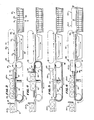
- FIG. 1 is a side elevational view of a pattern forming and container loading apparatus incorporating a product orienting apparatus constructed in accordance with and embodying the features of the present invention;
- FIG. 2 is a fragmentary, top plan view of the apparatus illustrated in FIG. 1;
- FIGS. 3-6 are enlarged, partially diagrammatic, side elevational views of the apparatus of FIG. 1, illustrating the apparatus at different stages of its operation;
- FIGS. 7 and 8 are fragmentary, top plan views, similar to FIG. 2, illustrating the apparatus at two different stages of its operation;
- FIGS. 9 and 10 are fragmentary top plan views of the pattern forming region of the apparatus of FIG. 1, illustrating lateral movement of products in formation of a pattern; and
- FIGS. 11-26 are diagrammatic plan views of representative patterns which can be formed with the apparatus of FIG. 1.
- Referring to FIGS. 1 and 2 of the drawings, there is illustrated a system, generally designated by the
numeral 20, constructed in accordance with and embodying the features of the present invention, for forming groups of articles into patterns and loading the patterns into containers. Thesystem 20 includes aninfeed conveyor 21 which conveys individual articles along a longitudinal path and groups the articles into sets with each set containing one or more articles. The infeed conveyor feeds the sets of articles to a product orienter 30 which selectively reorients the sets and sequentially transports them to astaging deck 70 on which a predetermined pattern of the sets is assembled, the pattern then being moved as a unit to acontainer loader 80 for loading into associatedcontainers 85. The infeedconveyor 21, the product orienter 30, thestaging deck 70 and thecontainer loader 80 are all disposed in an in-line arrangement for moving the associated articles along a single longitudinal system path without moving the articles from the system path. - The infeed
conveyor 21 is of standard construction, including abed 22 supported on posts 23 (one shown). Aroller 24 is rotatably mounted at one end of thebed 22 and receives therearound anendless conveyor belt 25, the support reach of which moves in the direction of the arrow in FIG. 2 for moving articles along the longitudinal system path. Carried by thebed 22 is anupstanding support bracket 26 on which is mounted agrouping gate 27 movable into and out of the path of the products conveyed on the infeedconveyor 21, selectively to stop the conveyedarticles 28 to allow them to accumulate intosets 29 having any desired number ofarticles 28 therein. For purposes of illustration, thearticles 28 have been depicted as loaves of bread in plastic bags tied at one end to form a tail in a well known manner, with each loaf extending transversely of the system path, as illustrated in FIG. 2. However, it will be appreciated that thesystem 20 could be used for handling other types of articles. While the infeedconveyor 21 has been illustrated as relatively narrow, it will be appreciated that it could be substantially wider. Furthermore, there may be provided along the infeedconveyor 21, preferably upstream of thesupport bracket 26, a lane-diverting mech- ansim for shifting the incoming train ofarticles 28 laterally of the infeedconveyor 21. Thus, the incoming train ofarticles 28 could be selectively positioned at either side of the infeedconveyor 21 or centrally thereof. Also, if desired, selected ones or groups of thearticles 28 could be shifted in this manner. Several types of such lane diverting mechanisms are known, one type being sold by Velten & Pulver, Inc., under the trademark "SELECT-O-FLOW". - The
product orienter 30 includes aframe 31 comprising a plurality ofupright posts 32 interconnected at the upper ends thereof bycrossbars 33 and interconnected adjacent to the lower ends thereof bycrossbars 34.Beams 35 and 36 are disposed intermediate the upper and lower ends of theposts 32 and extend horizontally for supporting associated equipment in a manner to be described below. Theproduct orienter 30 includes an endless window roller conveyor, generally designated by thenumeral 40. Thewindow conveyor 40 includes a pair of laterally spaced-apartendless chains upper sprockets 43 and a pair oflower sprockets 34 and behind atensioning sprocket 45, corresponding sprockets of the twochains common shafts 46 for rotation about the axes thereof. Thewindow conveyor 40 includes a conveyor section, generally designated by thenumeral 47, comprising a plurality of freely-rotatingrollers 48, each having the opposite ends thereof respectively secured to thechains rollers 48 being spaced apart longitudinally of thechains window conveyor 40 also includes awindow section 49 which comprises a gap wherein norollers 48 are provided. - The
upper sprockets 43 cooperate to define therebetween the upper flight of thewindow conveyor 40. When theconveyor section 47 is disposed along the upper flight, the upper surfaces of therollers 48 cooperate to define a substantially horizontal support plane. Thetensioning sprockets 45 are carried onadjustment brackets 50 which are, in turn, supported on upright members 51 of theframe 31. Theadjustment brackets 50 are movable for adjusting the tension in thechains window conveyor 40 is positioned so that the entry end of the support flight thereof is disposed closely adjacent to the exit end of the infeedconveyor 21. - The
shaft 46 for the lower sprockets 44 at the entry end of thewindow conveyor 40 is supported in pillow blocks 52 (one shown) and carries on one end thereof a sprocket (not shown) engaging anendless chain 53, which also engages asprocket 54 on a shaft rotatably supported outboard of theframe 31. Thesprocket 54 is a double sprocket and also engages achain 55, which is disposed in engagement with asprocket 56 mounted on the end of theroller 24 of the infeedconveyor 21. Thus, it will be appreciated that driving force is imparted to thewindow conveyor 40 from the infeedconveyor 21 by means of thechains conveyor 21 is driven by an associated drive unit (not shown) such as an electric motor. - Overlying the upper flight of the
window conveyor 40 adjacent to one end of therollers 48 is anelongated shoe 57 connected to the piston of an air cylinder 58 which is carried by a support 59 mounted on theframe 31 for effecting vertical reciprocating movement of theshoe 57 between a retracted position illustrated in FIG. 1 and a lower operating position in frictional engagement with the upper surfaces of therollers 48 of the window conveyor 40 (see FIG. 4). It will be appreciated that when theshoe 57 is disposed in its operating position the clockwise rotation of thewindow conveyor 40, as viewed in FIG. 1, results in a counter-clockwise rotation of therollers 48 along the upper flight of thewindow conveyor 40 about their axes for causing articles supported thereon to be held stationary for a purpose to be explained more fully below. A window roller conveyor is disclosed, for example, in U.S. Patent No. 4,030,620. - The product orienter 30 also includes a turntable assembly, generally designated by the
numeral 60, carried by theframe 31. More particularly, theturntable assembly 60 includes amotor 61 mounted on abracket 62 supported on thebeams 35, themotor 61 having a vertically upwardly extendingoutput shaft 63 which is fixedly secured to a hub 64 of acircular platform 65. The upper surface of theplatform 65 is disposed immediately beneath the up- per flight of thewindow conveyor 40 closely adjacent thereto and substantially parallel to the support plane thereof. Theplatform 65 is disposed in acircular aperture 66 in arectangular support plate 67 carried by theframe 31, the upper surfaces of thesupport plate 67 and theplatform 65 being substantially coplanar for providing a substantially continuous support surface. Theplatform 65 is mounted for rotation about the axis of theshaft 63, the peripheral edge of theplatform 65 being disposed very closely adjacent to the surrounding edge of thesupport plate 67. Carried by theframe 31 and overlying thewindow conveyor 40 are twogates conveyor 21 and thewindow conveyor 40 for pivotal movement into and out of the path of articles conveyed thereby. - The staging
deck 70 includes a frame having parallel side rails 71 and support posts 72. Rotatably supported between the side rails 71 are a plurality of longitudinally spaced-apart and transversely extendingsegmented rollers 73, each being rotatable about the axis of a shaft 73a. Each of therollers 73 includes four laterally- alignedsegments segments 74 cooperate to define asection 76 of the stagingdeck 70, while the segments 74a- cooperate to define asection 76a, thesegments 75 cooperate to define asection 77, and thesegments 75a cooperate to define asection 77a, thesections deck 70. The upper surfaces of therollers 73 cooperate to define a support surface which is disposed substantially coplanar with the upper surface of theturntable platform 65, with the entry end of the stagingdeck 70 disposed closely adjacent to the exit end of thesupport plate 67 of theturntable assembly 60. Overlying the stagingdeck 70 along one side edge thereof is anelongated pusher bar 78 secured to the piston of anair cylinder 79, disposed for effecting reciprocating movement of thepusher bar 78 transversely of the system path. - The
container loader 80 includes aretractable support plate 81, the upper surface of which is disposed just below the level of therollers 73 of the stagingdeck 70. Thesupport plate 81 is mounted for sliding horizontal movement in an associated frame and is provided at one end thereof with a pair ofclevis brackets 82, respectively coupled by connectingrods 83 to an associated drive mechanism (not shown) for effecting reciprocating movement of thesupport plate 81 between a normal support position illustrated in solid line in FIG. 1 and a retracted position disposed beneath the stagingdeck 70, and illustrated in broken line in FIG. 1. - Alternatively, the
support plate 81 could be mounted so that in its normal support position its upper surface is substantially coplanar with the support surface defined by therollers 73 of the stagingdeck 70. In this case, thesupport plate 81 could be fitted with cams which lower it upon retraction so that it can pass beneath the rollers of the stagingdeck 70, and raise it upon return to its normal support position. In this way the conveyed articles would not have to drop on to thesupport plate 81. - Disposed beneath the
support plate 81 is acontainer conveyor 84, which may be of any desired type, for conveyingcontainers 85 such as baskets or the like to and from a loading position beneath thesupport plate 81. While, for purposes of illustration,empty containers 85 have been shown as approaching the loading station from beneath the stagingdeck 70, it will be appreciated that they could approach the loading position from any other desired direction. In the configuration illustrated in FIG. 1 thecontainer conveyor 84 would preferably enter laterally beneath the stagingdeck 70 so as to avoid interference with theproduct orienter 30. This arrangement also permitsempty containers 85 to be fed laterally beneath the stagingdecks 70 of a plurality of parallel production lines like that illustrated in FIG. 1, it being common in bakeries, for example, to have separate lines for different types and sizes of product, several of which types may fit into the same type ofcontainer 85. Thecontainer conveyor 84 may leave the loading position beneath thesupport plate 81, either laterally of the system path or longitudinally to the right, as viewed in FIGS. 1 and 2. Alternatively, thecontainer conveyor 84 could enter directly beneath thesupport plate 81 laterally thereof and exit either laterally or longitudinally. - The
container loader 80 includes anair cylinder 86 having a vertically reciprocatingpiston rod 87 which is fixedly secured at the upper end thereof to aplate 88 carrying a plurality of upstandingparallel pins 89, which are much greater in number than the number of articles assembled in each pattern to be loaded in thecontainer 85. Thecontainer conveyor 84, and the bottom of each of thecontainers 85 are provided with a plurality of apertures for respectively receiving thepins 89 upwardly therethrough in the loading position, as illustrated in FIG. I, when thepiston rod 87 is in its fully extended position. The upper ends of thepins 89 are substantially coplanar and define a support plane which is spaced a slight distance beneath thesupport plate 81 when thepiston rod 87 is in its fully extended position. When thepiston rod 87 is retracted, the pins are completely withdrawn to a position (not shown) beneath thecontainer conveyor 84. Such retractable pin container loaders are disclosed, for example, in U.S. Patents Nos. 4,030,620 and 4,154,043. - The-staging
deck 70 is provided with a discharge mechanism 90 for transferring completed patterns of articles formed thereon to thecontainer loader 80. The discharge mechanism 90 may be of any of several types but, for purposes of illustration, it is shown as including a continuous chain 91 carrying twopusher bars 92 at equidistantly spaced-apart locations thereon, each of the pusher bars 92 projecting over the stagingdeck 70 parallel thereto and transversely of the system path. The chain 91 has a lower reach extending longitudinally of the system path and so positioned that when the pusher bars 92 are disposed along that reach they extend only a slight distance above the stagingdeck 70 for engagement with a pattern of articles thereon to move the pattern as a unit longitudinally from the stagingdeck 70 to thesupport plate 81 of thecontainer loader 80. - It will be appreciated that the pincushion type of
container loader 80 described above is merely illustrative, and other types of container loading devices could be used for different types of containers. Thus, for example, for very shallow types of containers such as trays or the like, the empty container could simply be fed forwardly (to the right as viewed in FIG. 1) from beneath the stagingdeck 70 in synchronism with the discharge mechanism 90 thereof, the conveyedarticles 28 being allowed to fall directly into the container as they leave the end of the stagingdeck 70. - It will be appreciated that a suitable electrical control circuit (not shown) will be provided for the
system 20 to control the operation thereof, the control circuit including suitable sensors, such as photoelectric sensors, limit switches and the like, in a well known manner. The circuitry will also include suitable sequencing means which is selectively operable for operating thesystem 20 in any of a number of different predetermined sequences for respectively forming different predetermined patterns ofarticles 28. Representative patterns ofarticles 28 which can be formed with thesystem 20 are illustrated, respectively, in FIGS. 11 through 26. In each of these figures the pattern is shown in its final configuration as it leaves the stagingdeck 70 and is loaded into thecontainer loader 80. All of the patterns are generally rectangular in outline to correspond with arectangular container 85, and it will be assumed that the four corners of the pattern fit respectively in the four corners of thecontainer 85. In those patterns where this condition does not obtain, the unoccupied corners of thecontainer 85 are diagrammatically illustrated in broken line. Different shapes and sizes of container and different shapes and sizes ofarticle 28 can be accommodated with the present invention. Thus, the patterns of FIGS. 11-26 include examples of different sizes and shapes ofarticles 28. - The long dimension of the
container 85 could be disposed either parallel.to or perpendicular to the longitudinal axis of the system path. Each of the patterns is illustrated in top plan view, so that the stagingdeck 70 is to the left. Thus, the pattern arrives from the left and the individual sets of articles in each pattern arrive at the stagingdeck 70 from the left. To facilitate an understanding of the formation of the patterns, thesets 29 of articles in each pattern are respectively numbered with encircled numerals in the order in which they arrive at the stagingdeck 70, and each set 29 bears a designation indicating the angular rotation which it undergoes on theproduct orienter 30. Thus, for example, the designation "0°" indicates that the set of articles passes through theproduct orienter 30 without rotation; the designation "90° CW" indicates that the set was rotated 90° clockwise; and the designation "90° CCW" indicates that the set was rotated 90° counterclockwise. - Referring now also to FIGS. 3 through 8 of the drawings, the operation of the
system 20 will be described in detail. For purposes of illustration, the operation will be described during formation of the pattern illustrated in FIG. 14, and that in order better to correlate this description with FIG. 14, thefirst set 29 of the pattern of FIG. 14 has been designated 29-1 in FIGS. 3-8, while the second set has been designated 29-2. It will be understood that normally thesystem 20 will be set to form a particular pattern and will typically operate repeatedly to form that pattern through a large number of cycles. If the type of product article or the type of container being handled is changed, then the pattern will have to be changed and this will necessitate changes in settings of the associated control circuit.. - Typically, the
articles 28 are conveyed from left to right along theinfeed conveyor 21, with the long dimension of thearticles 28 being disposed transversely of the path of travel and with the tail of thearticle 28 disposed downwardly, as viewed in FIGS. 2, 7 and 8. - The
articles 28 are spaced apart along theinfeed conveyor 21 and are accummulated by the groupinggate 27 intosets 29. In the configuration illustrated each set 29 will comprise fourarticles 28. Thus, thegate 27 may be moved down to its position blocking the path of thearticles 28 along theinfeed conveyor 21 for stopping them and allowing theconveyor belt 25 to pass therebeneath until fourarticles 28 have been accumulated in a side-by-side contiguous set 29, at which time thegate 27 is lifted to allow theset 29 to pass to the exit end of theinfeed conveyor 21. It will be appreciated that many types of accumulating devices for conveyor systems are known and that any suitable accumulating mechanism could be used to form thesets 29, thegate 27 being described simply for purposes of illustration. - When the first set 29-1 reaches the exit end of the
infeed conveyor 21, it is stopped by thegate 68 and held until the appropriate time for entry onto theproduct orienter 30. Theinfeed conveyor 21 is positioned so that the set 29-1 will enter upon theproduct orienter 30 toward the upper half of theturntable platform 65, as viewed in FIG. 2, and this configuration is used for formation of all of the patterns illustrated in FIGS. 11-26. However, it will be appreciated that, if desired for the.formation of other types of patterns, the positioning of theinfeed conveyor 21 with respect to theproduct orienter 30 could be changed, or the lane diverting mechanism of theinfeed conveyor 21 could be operated, so that thesets 29 would enter at other locations along theplatform 65. - The
window conveyor 40 moves on demand in a clockwise direction, as viewed in FIG. 1. When the leading end of theconveyor section 47 arrives at the upper flight of the window conveyor, thegate 68 is lifted and theinfeed conveyor 21 feeds the set 29-1 onto theconveyor section 47 of thewindow conveyor 40. In this regard, it will be appreciated that the adjacent ends of theinfeed conveyor 21 and thewindow conveyor 40 are closely spaced a distance substantially less than the width of a conveyedarticle 28 so that thearticles 28 pass freely between the two conveyors without interruption. Alternatively, transition support means between the two conveyors could be provided, if desired, in a well known manner. Theconveyor section 47 of thewindow conveyor 40 supports the set 29-1 and conveys it to the right over thesupport plate 67 and theplatform 65. When theentire set 29 has moved onto thewindow conveyor 40, thegate 68 is returned to its blocking position for stopping the next set 29-2 on theinfeed conveyor 21, as illustrated in FIG. 3. - As the set 29-1 is conveyed over the
platform 65 by thewindow conveyor 40, thegate 69 is lowered to its blocking position, illustrated in FIG. 4, to prevent the conveyedarticles 28 from being fed off theproduct orienter 30. When the first set 29-1 has reached the predetermined desired location over theplatform 65, theshoe 57 is lowered into frictional engagement with therollers 48 of thewindow conveyor 40 along the upper flight thereof for causing the engaged rollers to rotate in a counterclockwise direction, as viewed in FIG. 4. This counterclockwise rotation of therollers 48 serves to hold the set 29-1 stationary while theconveyor section 47 of thewindow conveyor 40 continues to pass therebeneath substantially without friction. As the trailing end of theconveyor section 47 passes beneath thearticles 28 of the set 29-1, thearticles 28 drop sequentially through thewindow section 49 onto theplatform 65. When the entire set 29-1 has dropped onto theplatform 65, theshoe 57 is lifted back to its normal retracted position. - The
platform 65 is then rotated 90° clockwise to bring the set 29-1 to the position illustrated in FIG. 5, thewindow section 49 being long enough to accommodate unobstructed rotation of the set 29-1 through any desired angle up to 180°. When the leading end of theconveyor section 47 again arrives at the upper flight of thewindow conveyor 40, thegate 68 is lifted to allow the next set 29-2 to be conveyed onto thewindow conveyor 40, as indicated in FIG. 5. When the leading end of theconveyor section 47 reaches the reoriented set 29-1 it pushes it off theplatform 65 andsupport plate 67 and onto thesegmented rollers 73 of the stagingdeck 70, as indicated in FIG. - 6. It will be appreciated that the set 29-1 is now disposed with the longitudinal axes of the
individual articles 28 extending parallel to the longitudinal system path. Since the set 29-1 contains fourarticles 28, it spans all of thesections deck 70, as indicated in FIG. 7. Since therollers 73 are not powered, the set 29-1 remains at the entry end of the stagingdeck 70, with the tails of thearticles 28 all pointing back toward theproduct orienter 30. When the set 29-1 has passed from theplatform 65, thegate 68 is lowered to its blocking position. - The second set 29-2 is then stopped in the desired position over the
platform 65, and by operation of theshoe 57, is then dropped through thewindow section 49 onto theplatform 65, as described above. When the complete set 29-2 has been deposited on theplatform 65, theplatform 65 is rotated 90° counterclockwise to bring the set 29-2 to the position illustrated in FIG. 8. Then, as the leading end of theconveyor section 47 of thewindow conveyor 40 engages the set 29-2, it pushes it off theplatform 65 and thesupport plate 67 onto the stagingdeck 70, pushing the set 29-1 ahead of it so that the pattern of FIG. 14 results on the stagingdeck 70. - Before the set 29-1 of the next pattern is moved onto the staging
deck 70, the completed pattern is discharged therefrom by use of the discharge mechanism 90. Thus, the chain 91 is actuated for moving one of the pusher bars 92 down into engagement with the trailing end of the pattern and pushing it longitudinally off the stagingdeck 70 and onto thesupport plate 81 of thecontainer loader 80, as indicated in FIG. 6. The chain 91 is then stopped in the position illustrated in FIG. 6 to allow the next set 29-1 to be moved onto the stagingdeck 70, the lower one of the pusher bars 92 serving as a stop to preventarticles 28 from traveling off the end of the stagingdeck 70 until the desired time for discharge of the next pattern. Thesupport plate 81 is then retracted back beneath the stagingdeck 70 to the position illustrated in broken line in FIG. 6, retrograde movement of the pattern ofarticles 28 being prevented by thepusher bar 92. Thus, as thesupport plate 81 is retracted, the sets 29-1 and 29-2 of the formed pattern drop onto the upper ends of thepins 89, which are then lowered for lowering the pattern ofarticles 28 into thecontainer 85. The filledcontainer 85 is then conveyed away and an empty container is moved into loading position over thepins 89, which are then moved back up through the corresponding openings in the bottom of thecontainer 85 to their product-receiving position. Thesupport plate 81 is returned to its original loading position for receiving the next pattern ofarticles 28. - It will be appreciated that instead of the
support plate 81 being moved immediately back to its normal support position after discharge of the previous set of articles therefrom, it could be retained in its retracted position beneath the stagingdeck 70 until the next set ofarticles 28 is ready to be discharged therefrom by the discharge mechanism 90. Then, thesupport plate 81 could be moved back to its normal support position in synchronism with the movement of thepusher bar 92 so that the conveyed articles could drop sequentially thereonto, thereby avoiding any sliding relative movement of the conveyed articles with respect to thesupport plate 81. - Furthermore, it will be appreciated that the lateral feeding of the
empty containers 85 to thesystem 20 is accommodated by the presence of the stagingdeck 70. However, if a different type of feeding movement of thecontainers 85 were permissible, the stagingdeck 70 could be eliminated, and the sets ofarticles 28 could be discharged from theproduct orienter 30 directly to thecontainer loader 80, the patterns of articles then being formed directly on thesupport plate 81. - The operation of the
system 20 is similar for formation and loading of each of the other patterns illustrated in FIGS. 11-19, 21, and 23-25. Thus, for each of these patterns, after each set 29 has undergone the indicated rotation on theturntable platform 65, it will be in position so that when it is discharged from theproduct orienter 30 it will move into the indicated pattern position, either directly or by being pushed into that position by succeedingsets 29 of the pattern. - However, in the case of the patterns of FIGS. 20, 22, and 26,
certain sets 29 of these patterns will not be in proper position as they exit theproduct orienter 30. In order to move these sets into proper position, thepusher bar 78 is used. Thus, referring, for example, to the pattern of FIG. 20, the first set 29-1 will be in proper position and can be pushed from theproduct orienter 30 directly onto the stagingdeck 70 and remain in that position. The second set 29-2 however, undergoes no rotation and, therefore, will simply be pushed across the top of theturntable assembly 60 and arrive on the stagingdeck 70 in the position illustrated in FIG. 9. The set 29-2 cannot remain in this position because the third set 29-3 also undergoes no rotation and will be discharged into the same position on the stagingdeck 70 occupied by the set 29-2. Accordingly, before discharge of the set 29-3 from theproduct orienter 30, the set 29-2 is moved laterally by thepusher bar 78 to the position illustrated in FIG. 10, thereby providing a space for the arrival of a set 29-3. Similar lateral movements by thepusher bar 78 are also necessary for thethird sets 29 of the patterns in FIGS. 22 and 26, as indicated by the arrows in those figures. - It will also be noted that for patterns such as those in FIGS. 22 and 26, the division of the staging
deck 70 intoparallel sections sets 29 deposited on one of the sections from being affected by later deposit of another set 29 on other sections. Thus, by the provision of four segments on each of therollers 73 all of the patterns illustrated in FIGS. 11-26 can be accommodated. - It will be understood that in the patterns described above, a rotation of 90° in one direction could be accomplished by a rotation of 270° in the opposite direction. Similarly, a rotation of 180° could be in either direction. The directions indicated in FIGS. 11-26 are merely illustrative. In the formation of any pattern the
system 20 is arranged so that as each set 29 is conveyed onto theproduct orienter 30 it will stop in a position corresponding to the upper right-hand corner of thecontainer 85, as viewed in FIGS. 11-26. This is controlled by the positioning of thestop 69 longitudinally of the system path and the lateral positioning of theinfeed conveyor 21 or the position of the lane-diverting mechanism thereof. - If a different shape container is used or if the
container 85 is to be loaded in a different orientation, a corresponding adjustment of the stopping location of each set 29 on theproduct orienter 30 must be made. - While the preferred embodiment of the invention has been described, it will be understood that a number of modifications thereof are possible. Thus, as indicated above, any of several different types of product accumulating devices could be used for grouping the
articles 28 into sets on theinfeed conveyor 21. While apusher bar 78 has been disposed along the upper side of the stagingdeck 70, as viewed in FIG. 2, it will be appreciated that it could also be disposed along the opposite side or on both sides, depending on the particular patterns to be formed. Alternatively, thepusher bar 78 could be eliminated entirely, and the lane diverting mechanism of theinfeed conveyor 21 could be used for selectively shifting the lateral positioning ofsets 29 on theproduct orienter 30 to avoid interference with other sets on the stagingdeck 70. While the stagingdeck 70 has been disclosed as comprised ofsegmented rollers 73 for minimal friction, it will be appreciated that a flat plate could also be used. Theshoe 57 has been described for facilitating shifting ofsets 29 through thewindow section 49 of thewindow conveyor 40, theshoe 57 could be eliminated and thestop 69 could alone serve to sweep thesets 29 off the trailing edge of theconveyor section 47 and onto theplatform 65. Finally, while discharge from the stagingdeck 70 has been described as being longitudinally of the system path, once the pattern has been formed it could be discharged from the stagingdeck 70 in any direction except back toward theproduct orienter 30. - From the foregoing, it can be seen that there has been provided an improved pattern former and product orienter therefor which is characterized by a completely in-line operation, the product reorienting and pattern forming all being accomplished along the longitudinal path of travel of articles through the
system 20. Thus, since theproduct orienter 30 is disposed directly in the longitudinal path of travel of the articles along thesystem 20, the articles can be fed longitudinally directly onto and off of theproduct orienter 30 without any changes in direction of the path of travel of the articles. This results in a system of simplified construction characterized by minimum handling of the articles. Furthermore, reorientation of the article sets is accomplished by theproduct orienter 30 without the necessity of displacing the sets vertically from the system path.
Claims (13)
Applications Claiming Priority (2)
| Application Number | Priority Date | Filing Date | Title |
|---|---|---|---|
| US06/457,431 US4522292A (en) | 1983-01-12 | 1983-01-12 | Pattern forming apparatus and product orienter therefor |
| US457431 | 1983-01-12 |
Publications (3)
| Publication Number | Publication Date |
|---|---|
| EP0114057A2 true EP0114057A2 (en) | 1984-07-25 |
| EP0114057A3 EP0114057A3 (en) | 1986-01-08 |
| EP0114057B1 EP0114057B1 (en) | 1988-07-13 |
Family
ID=23816703
Family Applications (1)
| Application Number | Title | Priority Date | Filing Date |
|---|---|---|---|
| EP84100198A Expired EP0114057B1 (en) | 1983-01-12 | 1984-01-10 | Pattern forming apparatus and product orientor therefor |
Country Status (5)
| Country | Link |
|---|---|
| US (1) | US4522292A (en) |
| EP (1) | EP0114057B1 (en) |
| JP (1) | JPS59177213A (en) |
| CA (1) | CA1221053A (en) |
| DE (1) | DE3472658D1 (en) |
Cited By (2)
| Publication number | Priority date | Publication date | Assignee | Title |
|---|---|---|---|---|
| EP0590664A2 (en) * | 1992-09-30 | 1994-04-06 | ADVANCED PULVER SYSTEMS Inc. | Product orienter and loader |
| EP0957049A1 (en) * | 1998-05-13 | 1999-11-17 | Selco Spa | Modular-station system for preparing and sorting packs of panels for supply to a stacking station |
Families Citing this family (24)
| Publication number | Priority date | Publication date | Assignee | Title |
|---|---|---|---|---|
| US4856263A (en) * | 1987-06-15 | 1989-08-15 | Advanced Pulver Systems, Inc. | System for loading patterns of articles into containers |
| US5145049A (en) * | 1990-10-12 | 1992-09-08 | Mcclurkin Jack | Pattern forming conveyor |
| DE4037593C1 (en) * | 1990-11-27 | 1992-01-30 | Hans Lingl Anlagenbau Und Verfahrenstechnik Gmbh & Co Kg, 7910 Neu-Ulm, De | |
| US6126383A (en) * | 1998-06-09 | 2000-10-03 | Hk Systems, Inc. | Apparatus for the in-line turning of selected articles |
| CN1074740C (en) * | 1998-09-22 | 2001-11-14 | 康佳集团股份有限公司 | Automatic stacker for household electricic appliance products, specialy TV sets |
| US6401435B1 (en) * | 1999-10-14 | 2002-06-11 | Sasib North America, Inc. | Pattern former and method of pattern forming for wrapped bakery products |
| US7191578B2 (en) * | 1999-10-14 | 2007-03-20 | Stewart Systems, Inc. | Pattern former for wrapped bakery products and bakery tray loading system |
| US6862869B2 (en) * | 1999-10-14 | 2005-03-08 | Stewart Systems, Inc. | Pattern former for wrapped bakery products |
| US7305806B2 (en) * | 1999-10-14 | 2007-12-11 | Stewart Systems, Inc. | Pattern former for wrapped bakery products and method for loading and unloading bakery products |
| US6499583B1 (en) * | 2000-11-17 | 2002-12-31 | Sohlberg Oerjan | Apparatus and a method for feeding articles |
| US6520314B1 (en) | 2002-01-30 | 2003-02-18 | Samuel O. Seiling | Apparatus for arranging packaged bakery goods for shipment |
| US6763750B2 (en) | 2002-02-07 | 2004-07-20 | Formax, Inc. | Conveyor system for slicer apparatus |
| DE102004012043A1 (en) * | 2004-03-11 | 2005-09-29 | Siemens Ag | Device and method for the positionally correct transfer of cuboid goods |
| FI20050908L (en) * | 2005-09-12 | 2007-03-13 | Metso Paper Inc | Method and device for turning paper rolls |
| US8122689B2 (en) * | 2007-01-24 | 2012-02-28 | Schur International A/S | Method and apparatus for producing, bagging and dispensing ice |
| DK200900512A (en) * | 2009-04-21 | 2010-10-22 | Schur Technology As | Method and apparatus for distributing items in a storage room |
| US7856797B2 (en) * | 2008-04-03 | 2010-12-28 | Arm Automation, Inc. | Automated collector device and methods |
| DE102008052769A1 (en) * | 2008-10-22 | 2010-04-29 | Krones Ag | Method for loading pallets and for forming pallet layers with cuboid objects |
| US9409726B2 (en) | 2010-09-17 | 2016-08-09 | Reddy Ice Technology Llc | Method and apparatus for distributing articles in a storage compartment |
| US8534034B1 (en) | 2012-08-02 | 2013-09-17 | Schur Technology A/S | Method and apparatus for distributing and storing serially produced articles in multiple storage units |
| US9562711B2 (en) | 2013-01-11 | 2017-02-07 | Reddy Ice Technology Llc | Method and apparatus for storing and dispensing bagged ice |
| JP6254041B2 (en) * | 2014-04-11 | 2017-12-27 | 澁谷工業株式会社 | Article conveying device |
| US10227201B2 (en) * | 2015-12-16 | 2019-03-12 | Toshiba International Corporation | Automated mail tray loading system and method |
| CN112694054A (en) * | 2020-12-26 | 2021-04-23 | 南京恒昌包装机械有限公司 | Packagine machine piles up distance device |
Citations (7)
| Publication number | Priority date | Publication date | Assignee | Title |
|---|---|---|---|---|
| US2971659A (en) * | 1956-10-29 | 1961-02-14 | Miller Engineering Corp | Apparatus for palletizing |
| FR1577343A (en) * | 1968-03-29 | 1969-08-08 | ||
| US3739902A (en) * | 1970-09-21 | 1973-06-19 | Baker Perkins Inc | Pattern maker |
| US3779363A (en) * | 1970-09-21 | 1973-12-18 | Baker Perkins Inc | Disc type pattern maker and method |
| US4030620A (en) * | 1975-12-15 | 1977-06-21 | Velten & Pulver, Inc. | Apparatus and method for loading containers |
| US4067456A (en) * | 1975-12-05 | 1978-01-10 | Columbia Machine, Inc. | Apparatus for arranging and stacking nonrigid articles |
| US4154043A (en) * | 1978-02-10 | 1979-05-15 | Velten & Pulver, Inc. | Container loading system |
Family Cites Families (7)
| Publication number | Priority date | Publication date | Assignee | Title |
|---|---|---|---|---|
| US1914806A (en) * | 1932-04-29 | 1933-06-20 | Hormel August | Apparatus for feeding metal plates |
| US2985322A (en) * | 1958-02-07 | 1961-05-23 | Coe Mfg Co | Apparatus for handling rigid sheet material |
| US4176741A (en) * | 1977-09-15 | 1979-12-04 | Redington Inc. | Article transfer mechanism |
| US4205742A (en) * | 1978-08-23 | 1980-06-03 | Abrahamson Daniel P | Cubing system |
| JPS5614261U (en) * | 1979-07-13 | 1981-02-06 | ||
| DE2952624A1 (en) * | 1979-12-28 | 1981-07-02 | Großbuchbinderei Sigloch GmbH & Co KG, 7118 Künzelsau | DEVICE FOR GROUPING OBJECTS IN STACKED LAYERS FOR LOADING PALLETS |
| JPS5846418B2 (en) * | 1980-02-19 | 1983-10-17 | 三洋電機株式会社 | Parts progressive feeding device |
-
1983
- 1983-01-12 US US06/457,431 patent/US4522292A/en not_active Expired - Lifetime
-
1984
- 1984-01-10 DE DE8484100198T patent/DE3472658D1/en not_active Expired
- 1984-01-10 EP EP84100198A patent/EP0114057B1/en not_active Expired
- 1984-01-11 CA CA000445118A patent/CA1221053A/en not_active Expired
- 1984-01-12 JP JP59004249A patent/JPS59177213A/en active Granted
Patent Citations (7)
| Publication number | Priority date | Publication date | Assignee | Title |
|---|---|---|---|---|
| US2971659A (en) * | 1956-10-29 | 1961-02-14 | Miller Engineering Corp | Apparatus for palletizing |
| FR1577343A (en) * | 1968-03-29 | 1969-08-08 | ||
| US3739902A (en) * | 1970-09-21 | 1973-06-19 | Baker Perkins Inc | Pattern maker |
| US3779363A (en) * | 1970-09-21 | 1973-12-18 | Baker Perkins Inc | Disc type pattern maker and method |
| US4067456A (en) * | 1975-12-05 | 1978-01-10 | Columbia Machine, Inc. | Apparatus for arranging and stacking nonrigid articles |
| US4030620A (en) * | 1975-12-15 | 1977-06-21 | Velten & Pulver, Inc. | Apparatus and method for loading containers |
| US4154043A (en) * | 1978-02-10 | 1979-05-15 | Velten & Pulver, Inc. | Container loading system |
Cited By (4)
| Publication number | Priority date | Publication date | Assignee | Title |
|---|---|---|---|---|
| EP0590664A2 (en) * | 1992-09-30 | 1994-04-06 | ADVANCED PULVER SYSTEMS Inc. | Product orienter and loader |
| EP0590664A3 (en) * | 1992-09-30 | 1994-09-21 | Advanced Pulver Systems Inc | Product orienter and loader |
| EP0765808A3 (en) * | 1992-09-30 | 1997-07-23 | Advanced Pulver Systems Inc | Product loader |
| EP0957049A1 (en) * | 1998-05-13 | 1999-11-17 | Selco Spa | Modular-station system for preparing and sorting packs of panels for supply to a stacking station |
Also Published As
| Publication number | Publication date |
|---|---|
| JPH0448692B2 (en) | 1992-08-07 |
| EP0114057A3 (en) | 1986-01-08 |
| CA1221053A (en) | 1987-04-28 |
| US4522292A (en) | 1985-06-11 |
| EP0114057B1 (en) | 1988-07-13 |
| JPS59177213A (en) | 1984-10-06 |
| DE3472658D1 (en) | 1988-08-18 |
Similar Documents
| Publication | Publication Date | Title |
|---|---|---|
| EP0114057B1 (en) | Pattern forming apparatus and product orientor therefor | |
| US5372472A (en) | Palletizer and palletizing methods | |
| US3954190A (en) | Palletizer | |
| US4018325A (en) | Automatic package accumulator | |
| CN110431095B (en) | Device for producing batches of products from a plurality of products | |
| US3934713A (en) | Method and apparatus for palletizing articles | |
| EP1161389B1 (en) | Apparatus and method for assembling items onto a pallet | |
| PL179999B1 (en) | Apparatus for and method of reloading and putting in place | |
| US3657860A (en) | Apparatus for the collation and packing of articles | |
| EP2397428B1 (en) | Apparatus and method for stacking packaging units | |
| US4192121A (en) | Case packing apparatus | |
| US4560057A (en) | Packet handling apparatus | |
| GB1596169A (en) | Case packing apparatus | |
| US3523617A (en) | Material handling system | |
| US4648770A (en) | Stacking profile elements in nested groups | |
| EP0173436B1 (en) | Improvements in collation assemblies | |
| US4073387A (en) | Method and apparatus for tier forming on a row by row basis | |
| US4440386A (en) | Apparatus for forming stacks ready to be packaged from flat workpieces | |
| SK30094A3 (en) | Method of transporting of products and device for realization of this method | |
| US4645062A (en) | Transfer apparatus for flat items | |
| US4205742A (en) | Cubing system | |
| US2815112A (en) | Article conveying and transferring mechanism | |
| EP0317198A2 (en) | Packaging systems and packaging processes | |
| GB2044712A (en) | Apparatus for Changing the Orientation of Articles on a Conveyor | |
| GB2103168A (en) | Packet handling apparatus |
Legal Events
| Date | Code | Title | Description |
|---|---|---|---|
| PUAI | Public reference made under article 153(3) epc to a published international application that has entered the european phase |
Free format text: ORIGINAL CODE: 0009012 |
|
| AK | Designated contracting states |
Designated state(s): DE FR GB |
|
| PUAL | Search report despatched |
Free format text: ORIGINAL CODE: 0009013 |
|
| AK | Designated contracting states |
Designated state(s): DE FR GB |
|
| 17P | Request for examination filed |
Effective date: 19860613 |
|
| 17Q | First examination report despatched |
Effective date: 19870203 |
|
| GRAA | (expected) grant |
Free format text: ORIGINAL CODE: 0009210 |
|
| AK | Designated contracting states |
Kind code of ref document: B1 Designated state(s): DE FR GB |
|
| REF | Corresponds to: |
Ref document number: 3472658 Country of ref document: DE Date of ref document: 19880818 |
|
| ET | Fr: translation filed | ||
| PLBE | No opposition filed within time limit |
Free format text: ORIGINAL CODE: 0009261 |
|
| STAA | Information on the status of an ep patent application or granted ep patent |
Free format text: STATUS: NO OPPOSITION FILED WITHIN TIME LIMIT |
|
| 26N | No opposition filed | ||
| PGFP | Annual fee paid to national office [announced via postgrant information from national office to epo] |
Ref country code: FR Payment date: 19961216 Year of fee payment: 14 |
|
| PGFP | Annual fee paid to national office [announced via postgrant information from national office to epo] |
Ref country code: DE Payment date: 19961218 Year of fee payment: 14 |
|
| PGFP | Annual fee paid to national office [announced via postgrant information from national office to epo] |
Ref country code: GB Payment date: 19961220 Year of fee payment: 14 |
|
| PG25 | Lapsed in a contracting state [announced via postgrant information from national office to epo] |
Ref country code: GB Free format text: LAPSE BECAUSE OF NON-PAYMENT OF DUE FEES Effective date: 19980110 |
|
| PG25 | Lapsed in a contracting state [announced via postgrant information from national office to epo] |
Ref country code: FR Free format text: THE PATENT HAS BEEN ANNULLED BY A DECISION OF A NATIONAL AUTHORITY Effective date: 19980131 |
|
| GBPC | Gb: european patent ceased through non-payment of renewal fee |
Effective date: 19980110 |
|
| PG25 | Lapsed in a contracting state [announced via postgrant information from national office to epo] |
Ref country code: DE Free format text: LAPSE BECAUSE OF NON-PAYMENT OF DUE FEES Effective date: 19981001 |
|
| REG | Reference to a national code |
Ref country code: FR Ref legal event code: ST |