EP0113596A1 - System für Verkehrszeichen - Google Patents
System für Verkehrszeichen Download PDFInfo
- Publication number
- EP0113596A1 EP0113596A1 EP83308036A EP83308036A EP0113596A1 EP 0113596 A1 EP0113596 A1 EP 0113596A1 EP 83308036 A EP83308036 A EP 83308036A EP 83308036 A EP83308036 A EP 83308036A EP 0113596 A1 EP0113596 A1 EP 0113596A1
- Authority
- EP
- European Patent Office
- Prior art keywords
- hinge block
- legs
- warning device
- view
- traffic
- Prior art date
- Legal status (The legal status is an assumption and is not a legal conclusion. Google has not performed a legal analysis and makes no representation as to the accuracy of the status listed.)
- Withdrawn
Links
- 230000011664 signaling Effects 0.000 title claims description 6
- 230000004888 barrier function Effects 0.000 claims description 18
- 230000008878 coupling Effects 0.000 description 16
- 238000010168 coupling process Methods 0.000 description 16
- 238000005859 coupling reaction Methods 0.000 description 16
- 239000004033 plastic Substances 0.000 description 3
- 229920003023 plastic Polymers 0.000 description 3
- 238000010276 construction Methods 0.000 description 2
- 230000003019 stabilising effect Effects 0.000 description 2
- 239000003086 colorant Substances 0.000 description 1
- 238000009432 framing Methods 0.000 description 1
- 238000004519 manufacturing process Methods 0.000 description 1
- 239000002184 metal Substances 0.000 description 1
- 230000004048 modification Effects 0.000 description 1
- 238000012986 modification Methods 0.000 description 1
- 230000008439 repair process Effects 0.000 description 1
- 239000011435 rock Substances 0.000 description 1
Images


Classifications
-
- E—FIXED CONSTRUCTIONS
- E01—CONSTRUCTION OF ROADS, RAILWAYS, OR BRIDGES
- E01F—ADDITIONAL WORK, SUCH AS EQUIPPING ROADS OR THE CONSTRUCTION OF PLATFORMS, HELICOPTER LANDING STAGES, SIGNS, SNOW FENCES, OR THE LIKE
- E01F9/00—Arrangement of road signs or traffic signals; Arrangements for enforcing caution
- E01F9/60—Upright bodies, e.g. marker posts or bollards; Supports for road signs
- E01F9/658—Upright bodies, e.g. marker posts or bollards; Supports for road signs characterised by means for fixing
- E01F9/669—Upright bodies, e.g. marker posts or bollards; Supports for road signs characterised by means for fixing for fastening to safety barriers or the like
-
- E—FIXED CONSTRUCTIONS
- E01—CONSTRUCTION OF ROADS, RAILWAYS, OR BRIDGES
- E01F—ADDITIONAL WORK, SUCH AS EQUIPPING ROADS OR THE CONSTRUCTION OF PLATFORMS, HELICOPTER LANDING STAGES, SIGNS, SNOW FENCES, OR THE LIKE
- E01F9/00—Arrangement of road signs or traffic signals; Arrangements for enforcing caution
- E01F9/60—Upright bodies, e.g. marker posts or bollards; Supports for road signs
- E01F9/688—Free-standing bodies
- E01F9/692—Portable base members therefor
Definitions
- This invention relates to apparatus for use as a traffic signalling system.
- the warning devices used as a signalling system at roadworks and other road hazards were in the form of coloured plastic cones. These were placed on the road surfaces to separate lanes of traffic, or mark the edges of roadworks. These cones, however, have several disadvantages. For safety reasons it is necessary that the cones are light enough to be easily knocked over and also that they are easily deformable on impact. However, when a cone is knocked over its shape is such that it can be easily moved by the wind. Thus, it may be moved away from its proper position and is liable to be run over by a passing vehicle.
- its shape and one piece construction mean that it can be so seriously damaged as to be subsequently unusable after being run over.
- apparatus for use as a traffic warning device comprising a central tube, an upper hinge block, a lower hinge block, a number of support legs, said legs being pivotally attached to said upper hinge block and a number of link arms, said link arms being pivotally attached at one end to the lower hinge block and at the other end each to a respective leg.
- said top hinge block is slidably mounted on the central tube in such a way that the legs may be folded in flat against the tube to allow easy storage and transportation.
- a number of support brackets and the like are provided, said support brackets allowing barriers, signs and the like to be attached to the warning device.
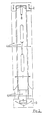
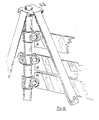
- a traffic warning device comprises a central plastics tube 1 having slidably mounted on it an upper hinge block 2 and mounted at its base a lower, hinge block 3.
- Four 'C' section plastic legs 4 and four 'C' section link arms 5 each have one of their ends pivotally mounted by way of pivot shafts 6 pivoting in mounting holes 7 in the hinge blocks 2, 3.
- the other end of each of the link arms 5 is pivotally mounted by way of pivot shafts 6 each to a respective leg 4.
- the legs 4 and links 5 have slots 8 at their ends to allow them to bend easily for attachment of the pivot shafts 6 to the mounting holes 7 in the hinge blocks 2, 3.
- slots 9 in the legs 4 serve to reduce to the wind resistance of the legs hence reduce the incidence of the device being blown over by the wind.
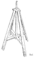
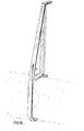
- the device In use, the device is removed from storage with the legs in the folded position as shown in Fig. 2.
- the legs 4 are then moved into the position shown in Fig. 1 by sliding the upper hinge block 2 down the central tube 1 causing the lower end of the legs 4 to move out from the base of the device as the link arms 5 pivot on the lower hinge block 3.
- the upper hinge pivot 2 When the arms are in their fully open position the upper hinge pivot 2 is prevented from sliding up the central tube 1, and hence refolding the legs 4, by a catch 10.
- the shafts 6 can be replaced with extra mounting holes and the parts joined with clips such as those shown in Figs. 12 and 13.
- a device having a number of legs other than four it is possible to manufacture a device having a number of legs other than four.
- a device with three legs requries triangular hinge blocks, etc.
- warning device can be used as a base for signs and barriers. It is possible to make a fence or barrier by joining up a number of devices with battens mounted on the top part of the tube. Similarly, road signs and warning lamps may be easily attached and the slots in the legs make it easy to run lengths of reflective tape between a number of warning devices.
- the warning devices may be manufactured in a number of different colours for use in different situations.
- the shape of the device is such that it may be mechanically laid. Should a device be run over by a vehicle its construction is such that in most cases it will be possible to repair it by simply replacing those parts which have been damaged.
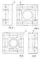
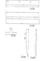
- Figs. 14a and 14b show a single lug tube coupling. This can be used as the end for a flat barrier, as shown in Fig. 32, or as the end for a round barrier when used in combination with the end tube coupling of Fig. 18. It can also be used to fix signs onto tubes or onto the warning device of Fig. l.
- Figs. 15a and 15b show a four lug tube coupling. This can be used for sign fixing or for sign frame stabilising. It can also be used to extend barriers in all directions from the device of Fig. 1 as shown in Fig. 32.
- Figs. 16a and 16b show a straight coupling for use in extending tubes or for fixing high signs onto the device of F ig. 1.
- the tubes may be provided with a catch 11, as shown in Fig. 17, which co-operates with a slot 12 on the straight coupling.
- the coupling may be fixed to the tubes with the clips shown in Figs. 12 and 13.
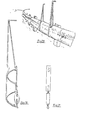
- Fig. 18 shows an end tube coupling. This can be used in combination with the single lug tube coupling of Fig. 14 and 14b or the four lug tube coupling of Figs. 15a and 15b to affix tubular barriers to the warning device of Fig. 1. It can be used as a sign support in combination with the sign support bracket of Figs. 25a, 25b and 25c or the ground plate of Figs. 27a, 27b and 27c. It can also be used in combination with the components of Figs. 19, 20, 21 and 22 to form the tensioner assembly shown in Fig. 23. This tensioner assembly can be used to tension the barrier clip of Fig. 30.
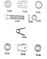
- Figs. 24a and 24b show a warning light for fixing to the top of the central tube of the warning device of Fig. 1.
- the batteries for the lamp fit inside the device at 13 and the lamp is operated by a locating and earthing screw 14.
- Figs. 25a, 25b and 25c show a sign support bracket. This bracket can be fitted to signs and removes the necessity for metal framing.
- the ground pin shown in Figs. 26a and 26b can be used to stabilise the legs of the device of Fig. 1 or the ground plate of Fig. 27.
- the ground plate of Figs. 27a, 27b and 27c allows barriers and signs to be fixed to the ground, using the ground pins of Figs. 26a and 26b, or to walls and rock faces using rails or bolts.
- the barrier clamps shown in Figs. 28 and 29 can be fitted in pairs to motorway barriers to support signs on the central reservation. The signs fit between the two clamps and thus hold the clamps in position.
- the barrier clamp shown in Fig. 30 can be used. This has a built in tensionery device and is thus self-supporting when fitted to a barrier.
- An example of a suitable tensioner is shown in Fig. 31.
Landscapes
- Engineering & Computer Science (AREA)
- Architecture (AREA)
- Civil Engineering (AREA)
- Structural Engineering (AREA)
- Road Signs Or Road Markings (AREA)
Applications Claiming Priority (2)
| Application Number | Priority Date | Filing Date | Title |
|---|---|---|---|
| GB8236925 | 1982-12-30 | ||
| GB8236925 | 1982-12-30 |
Publications (1)
| Publication Number | Publication Date |
|---|---|
| EP0113596A1 true EP0113596A1 (de) | 1984-07-18 |
Family
ID=10535279
Family Applications (1)
| Application Number | Title | Priority Date | Filing Date |
|---|---|---|---|
| EP83308036A Withdrawn EP0113596A1 (de) | 1982-12-30 | 1983-12-30 | System für Verkehrszeichen |
Country Status (1)
| Country | Link |
|---|---|
| EP (1) | EP0113596A1 (de) |
Cited By (3)
| Publication number | Priority date | Publication date | Assignee | Title |
|---|---|---|---|---|
| FR2676761A1 (fr) * | 1991-05-24 | 1992-11-27 | France Direc Rgle Expl Agen Au | Dispositif pour la fixation des panneaux de signalisation routiere sur les glissieres de securite. |
| GB2281579A (en) * | 1993-08-17 | 1995-03-08 | Rose Maureen Todd | Collapsible sign support |
| CN112796246A (zh) * | 2021-01-06 | 2021-05-14 | 陆波 | 一种建筑施工用警示装置 |
Citations (2)
| Publication number | Priority date | Publication date | Assignee | Title |
|---|---|---|---|---|
| US2781017A (en) * | 1954-03-23 | 1957-02-12 | Western Progress Inc | Signaling device |
| US3899843A (en) * | 1967-12-11 | 1975-08-19 | Western Progress Inc | Signalling device with a sign having provision for spilling of wind and with a support |
-
1983
- 1983-12-30 EP EP83308036A patent/EP0113596A1/de not_active Withdrawn
Patent Citations (2)
| Publication number | Priority date | Publication date | Assignee | Title |
|---|---|---|---|---|
| US2781017A (en) * | 1954-03-23 | 1957-02-12 | Western Progress Inc | Signaling device |
| US3899843A (en) * | 1967-12-11 | 1975-08-19 | Western Progress Inc | Signalling device with a sign having provision for spilling of wind and with a support |
Cited By (3)
| Publication number | Priority date | Publication date | Assignee | Title |
|---|---|---|---|---|
| FR2676761A1 (fr) * | 1991-05-24 | 1992-11-27 | France Direc Rgle Expl Agen Au | Dispositif pour la fixation des panneaux de signalisation routiere sur les glissieres de securite. |
| GB2281579A (en) * | 1993-08-17 | 1995-03-08 | Rose Maureen Todd | Collapsible sign support |
| CN112796246A (zh) * | 2021-01-06 | 2021-05-14 | 陆波 | 一种建筑施工用警示装置 |
Similar Documents
| Publication | Publication Date | Title |
|---|---|---|
| US6668474B2 (en) | Outdoor sign apparatus for real estate or other advertising purposes | |
| US4548379A (en) | Compact sign and stand | |
| US4593879A (en) | Compact sign stand | |
| US4666108A (en) | Extensible railroad grade crossing gate arm | |
| US4124196A (en) | Portable device for screening off an accident scene from view | |
| US6785991B2 (en) | Collapsible traffic control sign | |
| US20230391251A1 (en) | School Bus Safety Devices and Systems | |
| US6003827A (en) | Universal sign holder | |
| EP0113596A1 (de) | System für Verkehrszeichen | |
| US3380429A (en) | Traffic warning device | |
| US3738309A (en) | Collapsible warning device | |
| US3995250A (en) | Portable traffic signal light | |
| US5006009A (en) | Outdoor post assembly | |
| GB2148360A (en) | Yieldable hazard markers | |
| US20250332991A1 (en) | School Bus Safety Devices and Systems | |
| US4232466A (en) | Collapsible display frame | |
| US4706780A (en) | Ladder attaching device | |
| JP7253790B2 (ja) | 交通表示具の取付構造 | |
| US8424644B2 (en) | Bracket for connecting sawhorses | |
| CN213774798U (zh) | 一种具有夜间施工警示远离功能的建筑围挡 | |
| CN215808179U (zh) | 一种具有拼接功能的路灯灯杆 | |
| US7448824B2 (en) | Traffic barricade having interchangeable parts | |
| KR100475216B1 (ko) | 절첩식 공사안내 표시구 | |
| RU2264500C1 (ru) | Разъемное дорожное ограждение | |
| EP0639673A2 (de) | Ständer |
Legal Events
| Date | Code | Title | Description |
|---|---|---|---|
| PUAI | Public reference made under article 153(3) epc to a published international application that has entered the european phase |
Free format text: ORIGINAL CODE: 0009012 |
|
| AK | Designated contracting states |
Designated state(s): AT BE CH DE FR GB IT LI LU NL SE |
|
| 17P | Request for examination filed |
Effective date: 19841228 |
|
| STAA | Information on the status of an ep patent application or granted ep patent |
Free format text: STATUS: THE APPLICATION IS DEEMED TO BE WITHDRAWN |
|
| 18D | Application deemed to be withdrawn |
Effective date: 19870122 |