EP0113494B1 - Junction plate - Google Patents
Junction plate Download PDFInfo
- Publication number
- EP0113494B1 EP0113494B1 EP83303132A EP83303132A EP0113494B1 EP 0113494 B1 EP0113494 B1 EP 0113494B1 EP 83303132 A EP83303132 A EP 83303132A EP 83303132 A EP83303132 A EP 83303132A EP 0113494 B1 EP0113494 B1 EP 0113494B1
- Authority
- EP
- European Patent Office
- Prior art keywords
- auxiliary strut
- strut
- auxiliary
- channels
- plate
- Prior art date
- Legal status (The legal status is an assumption and is not a legal conclusion. Google has not performed a legal analysis and makes no representation as to the accuracy of the status listed.)
- Expired
Links
Images
Classifications
-
- E—FIXED CONSTRUCTIONS
- E04—BUILDING
- E04B—GENERAL BUILDING CONSTRUCTIONS; WALLS, e.g. PARTITIONS; ROOFS; FLOORS; CEILINGS; INSULATION OR OTHER PROTECTION OF BUILDINGS
- E04B1/00—Constructions in general; Structures which are not restricted either to walls, e.g. partitions, or floors or ceilings or roofs
- E04B1/18—Structures comprising elongated load-supporting parts, e.g. columns, girders, skeletons
- E04B1/19—Three-dimensional framework structures
- E04B1/1903—Connecting nodes specially adapted therefor
-
- E—FIXED CONSTRUCTIONS
- E04—BUILDING
- E04B—GENERAL BUILDING CONSTRUCTIONS; WALLS, e.g. PARTITIONS; ROOFS; FLOORS; CEILINGS; INSULATION OR OTHER PROTECTION OF BUILDINGS
- E04B1/00—Constructions in general; Structures which are not restricted either to walls, e.g. partitions, or floors or ceilings or roofs
- E04B1/32—Arched structures; Vaulted structures; Folded structures
- E04B1/3205—Structures with a longitudinal horizontal axis, e.g. cylindrical or prismatic structures
-
- E—FIXED CONSTRUCTIONS
- E04—BUILDING
- E04B—GENERAL BUILDING CONSTRUCTIONS; WALLS, e.g. PARTITIONS; ROOFS; FLOORS; CEILINGS; INSULATION OR OTHER PROTECTION OF BUILDINGS
- E04B1/00—Constructions in general; Structures which are not restricted either to walls, e.g. partitions, or floors or ceilings or roofs
- E04B1/18—Structures comprising elongated load-supporting parts, e.g. columns, girders, skeletons
- E04B1/19—Three-dimensional framework structures
- E04B1/1903—Connecting nodes specially adapted therefor
- E04B2001/1918—Connecting nodes specially adapted therefor with connecting nodes having flat radial connecting surfaces
-
- E—FIXED CONSTRUCTIONS
- E04—BUILDING
- E04B—GENERAL BUILDING CONSTRUCTIONS; WALLS, e.g. PARTITIONS; ROOFS; FLOORS; CEILINGS; INSULATION OR OTHER PROTECTION OF BUILDINGS
- E04B1/00—Constructions in general; Structures which are not restricted either to walls, e.g. partitions, or floors or ceilings or roofs
- E04B1/18—Structures comprising elongated load-supporting parts, e.g. columns, girders, skeletons
- E04B1/19—Three-dimensional framework structures
- E04B2001/1924—Struts specially adapted therefor
- E04B2001/1933—Struts specially adapted therefor of polygonal, e.g. square, cross section
-
- E—FIXED CONSTRUCTIONS
- E04—BUILDING
- E04B—GENERAL BUILDING CONSTRUCTIONS; WALLS, e.g. PARTITIONS; ROOFS; FLOORS; CEILINGS; INSULATION OR OTHER PROTECTION OF BUILDINGS
- E04B1/00—Constructions in general; Structures which are not restricted either to walls, e.g. partitions, or floors or ceilings or roofs
- E04B1/18—Structures comprising elongated load-supporting parts, e.g. columns, girders, skeletons
- E04B1/19—Three-dimensional framework structures
- E04B2001/1924—Struts specially adapted therefor
- E04B2001/1945—Wooden struts
-
- E—FIXED CONSTRUCTIONS
- E04—BUILDING
- E04B—GENERAL BUILDING CONSTRUCTIONS; WALLS, e.g. PARTITIONS; ROOFS; FLOORS; CEILINGS; INSULATION OR OTHER PROTECTION OF BUILDINGS
- E04B1/00—Constructions in general; Structures which are not restricted either to walls, e.g. partitions, or floors or ceilings or roofs
- E04B1/18—Structures comprising elongated load-supporting parts, e.g. columns, girders, skeletons
- E04B1/19—Three-dimensional framework structures
- E04B2001/1957—Details of connections between nodes and struts
- E04B2001/1963—Screw connections with axis at an angle, e.g. perpendicular, to the main axis of the strut
-
- E—FIXED CONSTRUCTIONS
- E04—BUILDING
- E04B—GENERAL BUILDING CONSTRUCTIONS; WALLS, e.g. PARTITIONS; ROOFS; FLOORS; CEILINGS; INSULATION OR OTHER PROTECTION OF BUILDINGS
- E04B1/00—Constructions in general; Structures which are not restricted either to walls, e.g. partitions, or floors or ceilings or roofs
- E04B1/32—Arched structures; Vaulted structures; Folded structures
- E04B2001/3235—Arched structures; Vaulted structures; Folded structures having a grid frame
- E04B2001/3241—Frame connection details
- E04B2001/3247—Nodes
-
- E—FIXED CONSTRUCTIONS
- E04—BUILDING
- E04B—GENERAL BUILDING CONSTRUCTIONS; WALLS, e.g. PARTITIONS; ROOFS; FLOORS; CEILINGS; INSULATION OR OTHER PROTECTION OF BUILDINGS
- E04B1/00—Constructions in general; Structures which are not restricted either to walls, e.g. partitions, or floors or ceilings or roofs
- E04B1/32—Arched structures; Vaulted structures; Folded structures
- E04B2001/3294—Arched structures; Vaulted structures; Folded structures with a faceted surface
-
- Y—GENERAL TAGGING OF NEW TECHNOLOGICAL DEVELOPMENTS; GENERAL TAGGING OF CROSS-SECTIONAL TECHNOLOGIES SPANNING OVER SEVERAL SECTIONS OF THE IPC; TECHNICAL SUBJECTS COVERED BY FORMER USPC CROSS-REFERENCE ART COLLECTIONS [XRACs] AND DIGESTS
- Y10—TECHNICAL SUBJECTS COVERED BY FORMER USPC
- Y10T—TECHNICAL SUBJECTS COVERED BY FORMER US CLASSIFICATION
- Y10T403/00—Joints and connections
- Y10T403/34—Branched
- Y10T403/341—Three or more radiating members
- Y10T403/342—Polyhedral
- Y10T403/343—Unilateral of plane
-
- Y—GENERAL TAGGING OF NEW TECHNOLOGICAL DEVELOPMENTS; GENERAL TAGGING OF CROSS-SECTIONAL TECHNOLOGIES SPANNING OVER SEVERAL SECTIONS OF THE IPC; TECHNICAL SUBJECTS COVERED BY FORMER USPC CROSS-REFERENCE ART COLLECTIONS [XRACs] AND DIGESTS
- Y10—TECHNICAL SUBJECTS COVERED BY FORMER USPC
- Y10T—TECHNICAL SUBJECTS COVERED BY FORMER US CLASSIFICATION
- Y10T403/00—Joints and connections
- Y10T403/44—Three or more members connected at single locus
Definitions
- This invention relates to metal junction plates for building structures in general, and, in particular, to junction plates intended to form connectors for polygonal geodesic building structures.
- the prior art is generally cognizant of the concept of building structures which are generally complex polygonal geometric structures constructed from a plurality of triangular planar face surfaces joined together at junction points.
- One typical method used for the construction of such geodesic type building structures is to utilize uniform sized struts which are joined together by connector plates at each junction point to fix the relationship between struts emanating in all directions from that junction plate.
- one convenient technique is to use stamped metal junction plates to facilitate the construction of the geodesic structures and to rigidify the orientation between the struts of a partial structure during the construction of the complete geometric structure.
- Examples of prior art juction plates utilized for the construction of such geodesic structures include US-A-3,844,664, US-A-3,857,212, US-A-3,270,478, US-A-:4,203,265, US-A-3,486,278, US-A-2,803,317 and US-A-3,990,195.
- These prior art junction plates used to facilitate the construction of geodesic structures are often very complex to use, requiring trained or skilled personnel, and making the construction of such structures impractical for inexperienced builders or homeowners who desire to construct such a structure for themselves.
- a junction plate formed by stamping from a metal disk and for securing a plurality of main struts together to form a polygonal geodesic structure, is characterised by a flat central portion; a skirt portion of the plate formed into a generally frusto-conical shape extending from the periphery of the plate to the central portion; a plurality of main strut channels formed into the skirt portion of the plate extending radially outward from the central portion, each of the main strut channels being bent relative to the central portion by an angle selected so that the channels are generally parallel to the main struts; and an auxiliary strut channel formed into the skirt portion between each of the main strut channels, the auxiliary strut channels being bent at an angle relative to the central portion so as to be generally parallel to the adjacent face of the polygonal geodesic structure so that an auxiliary strut inserted to support that face can be easily secured in the auxiliary strut channel of the plate with a minimum of shaping to
- each of the main struts may be secured in the respective main strut channel with the shape of the channel fixing the orientation between the individual strut and the junction plate. If the junction plate only included main strut channels it would be completely satisfactory for the erection of a geodesic type structure up to a given practical limit in size. This practical limit in size occurs because of the necessity for utilizing standard construction materials as the surface coverings to cover the triangular faces of the geodesic structure.
- Such standard building materials such as plywood, generally come in four foot sheets and thus are often not wide enough to bridge across a triangular face of a polygonal structure if the strut length on any of the faces of the triangle exceeds four feet.
- auxiliary struts may also be necessary to support the faces of the structures so proper loadings can be achieved. It is often difficult to firmly, accurately and quickly install such auxiliary struts into such a structure however and to securely fix them in place. Such installation also may require relatively sophisticated shaping of the ends of the auxiliary struts.
- junction plate of the invention by the provision of its auxiliary strut channels additionally facilitates the heretofore difficult problem of inserting auxiliary struts into the structure to support the surface facings of the structure at points intermediate the main struts in each of the triangular faces of the structure.
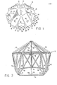
- a junction plate 10 of Fig. 1 is a metallic plate for joining structural frame members to form a polygonal geodesic building structure, such as the icosahedron illustrated in Fig. 2, and generally designated at 12.
- the junction plate 10 of Fig. 1 is particularly adapted and constructed so that it may be easily used to construct the geodesic structure 12 in a rapid and efficient manner by an unskilled user, and is particularly adapted for use in constructing larger structures in which auxiliary struts may be needed for structural support of surface faces the completed structure.
- the junction plate 10 is a generally frusto-conically shaped stamped metal plate formed from stamped sheet steel or other metallic material.
- the central portion of the junction plate 10 is a pentagonal central portion 14 which is a flat planar portion of the sheet metal material.
- a registration hole 16 is formed in the center of the base portion 16 to facilitate stamping of the plate 10. From the central portion 14 the remaining portion of the frusto-conical shape of the junction plate 10 turns outwarly and downwardly in a smooth conical fashion to form a skirt portion 17.
- a series of five identical main strut channels 18 are indented into the skirt portion 17 of the junction plate 10 and extend radially outward from the central portion 14.
- Each of the main strut channels 18 is defined by a respective bend line 20 joining the channel 18 to the central portion 14 at its inward end and by a pair of side bend lines 22 defining the sides of each of the channels 18.
- the bend at the bend line 20 is defined so that the channel 18 is oriented to be parallel to the main strut to which it fastens, as will be further discussed below.
- Each of the side bend lines 22 defines one side of one of generally upstanding vertical side walls 24 defining the sides of each of the main strut channels 18. The details of these components may also be viewed in Figs. 3 and 4.
- each of the side walls 24 increases in dimension from zero at the inside bend line 20 to a dimension at the periphery of the junction plate 10 being of sufficient size so as to be capable of retaining a main strut in place inside of the channel 18 as will be described below in further detail.
- a centrally located fastening hole 26 is formed in each of the main strut channels 18.
- auxiliary strut channel 30 Located in between each of the main strut channels 18 in an intervening section of the skirt portion 17 is an auxiliary strut channel 30.
- the five auxiliary strut channels 30 are also formed as inwardly indented portions of the cylindrical surface of the skirt portion 17 of the junction plate 10.
- Each of the auxiliary strut channels 30 is defined by an inward bend line 32 and by a pair of side bend lines 34.
- Sidewalls 36 form the sides of each of the auxiliary strut channels 30 and increase in dimension from zero at the inward bend line 30 to a dimension at the periphery of the junction plate 10 sufficient to restrain an auxiliary strut as.will be described below in more detail.
- auxiliary strut channels 30 are bent relative to the central portion 14 along the inward bend line 32 at an angle such that the auxiliary strut channel 30 is parallel to the adjacent surface face of the geodesic structure.
- Centrally formed in each of the auxiliary strut channels 30 is both a large bolt fastening hole 38 and two smaller nail fastening holes 40.
- the junction plate 10 of Fig. 1 is intended to be utilized in the construction of a polygonal geodesic building structure 12 as illustrated in Fig. 2.
- Each of the main struts 50 are preferably formed by pieces of conventional framing lumber, such as 2 x 4s, of equal length.
- Each of the main struts 50 has a single hole bored through it along its longer lateral axis adjacent to its ends so that it may be attached to the adjacent junction plate 10.
- Each end of each of the main struts 50 is then attached by a single bolt 60 to the adjacent junction plate 10.
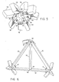
- Fig. 5 is an underside view showing the attachment of the main struts 50 to the junction plate 10.
- the main struts 50 require no alteration, shaping, or adaption to them prior to installation to the junction plate 10 other than the drilling of the single hole to receive the bolt 60.
- the assembly of the twenty-five main struts 50 together with the eleven junction plates 10 forms a structure as illustrated in Fig. 2 without the addition of the auxiliary struts 52 thereto.
- This structure thus formed is a polygonal geodesic structure which is composed of a plurality of triangular surface faces, one of which is illustrated in an enlarged view in Fig. 6.
- each of the surface faces of the polygonal structure 12 of Fig. 2 is defined by a triangle formed by three of the main struts 50.
- At each apex of the triangle formed by the three main struts 50 is one of the junction plates 10.
- Each of the channels 18 in each of the junction plates 10 is oriented so that the ends of the main struts 50 may be joined securely thereto, and it is for this reason that the angle of the channels 18 is selected to be parallel to the direction in which the adjacent main strut 50 extends. If the length of the main struts 50 exceeds four feet, which is often desirable, it can readily be seen by referring to Fig.
- auxiliary strut such as that illustrated at 52 in Fig. 6, is necessary.
- the auxiliary strut 52 is attached at one end to a junction plate 10 and at its other end to a midpoint of a one of the main struts 50.
- the junction plate 10 is particularly adapted to facilitate the installation of such auxiliary struts 52 into the surface faces of the polygonal geodesic structure, as illustrated in Fig. 2 so that larger structures can be easily and quickly constructed utilizing the junction plate 10.
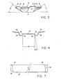
- auxiliary strut 52 To install the auxiliary strut 52 into the geodesic structure 12, some minimal shaping is required to the auxiliary strut 52. This shaping is illustrated in Fig. 7.
- the primary required shaping consists of the cutting of a rabbet 56 to the one end of the auxiliary strut 52.
- This rabbet must be sufficiently long in length, measured along the longitudinal axis of the auxiliary strut 52, to accommodate the auxiliary strut channel 30 of the junction plate 10 to which it is attached.
- a bolt hole 54 may be necessary adjacent to the rabbet 56 drilled through the longer lateral axis of the auxiliary strut 52 adjacent to the end thereof.
- a miter cut 58 should be made if it is desired to connect the opposite end of the auxiliary strut 52 directly to the main strut 50.
- another connecting bore hole 54 may be drilled. through the longer lateral axis of the auxiliary strut 52 if a metal connecting plate is to be bolted to the end of the auxiliary strut 52 to join it to the main strut 50. Even the bolt hole 54 at the opposite end of the auxiliary strut 50 may be omitted if the auxiliary strut 52 is nailed to a metal connecting plate fastened to the main strut 50.
- auxiliary strut 52 In installing the auxiliary strut 52 into a triangular face of the geodesic structure, as illustrated in Fig. 6, the auxiliary strut 52 is placed in position and a bolt 62 is inserted through the hole 54 drilled through the end of the auxiliary strut 52 having the rabbet 56.
- the rabbeted end of the auxiliary strut 52 is placed into the appropriate auxiliary strut channel 30 in-the junction plate 10 to which the auxiliary strut 52 is to be attached. This is illustrated at the top apex of the triangular face of the geodesic structure as illustrated in Fig. 6.
- the tightening of this bolt 62 will draw the rabbeted end of the auxiliary strut 52 into the auxiliary strut channel 30 formed in the junction plate 10.
- the auxiliary strut channel 30, which is defined on its lateral edges by the bend lines 34 which form one side of the side walls 36, had a width W. That width W is selected so as to correspond generally to the width of the auxiliary strut 52 along its shorter lateral axis. For conventional construction lumber this will be approximately Is inches.
- the side walls 36 of the auxiliary strut channel 30 will be selected so as to extend slightly outwardly from normal to the bottom of the auxiliary strut channel 30 by an angle of D. That angle will be selected to be approximately 10°.
- the auxiliary strut is pulled into the auxiliary strut channel 30 and the side walls 36 of the auxiliary strut channel 30 cam the auxiliary strut 52 into a fixed angular relationship relative to the junction plate 10.
- the other end of the auxiliary strut 52 can be attached to the oppositely oriented main strut 50 by a single nail 64 if the miter cut 58 has been made to the opposite end of the auxiliary strut 52, as is illustrated in the auxiliary strut 52 of Fig. 6.
- the auxiliary strut 52 may be clamped firmly in the channel 30 so that the side walls 36 can act on the auxiliary strut 52, and a pair of nails 63 may be driven through the nail holes 40 in the auxiliary strut channel 30, as illustrated at the bottom of Fig. 5.
- angles of the main strut channels 18 and the auxiliary strut channels 30 are particularly selected to facilitate the easy and rapid construction of the geodesic structure 12 of Fig. 2.
- the main strut channels 18 form an angle A relative to the central portion 14. That angle is selected so that the main strut channels 18 are oriented parallel to the angle at which the main struts 50 extend away from the junction plate 10.
- angle A should be selected to be approximately 31.7°.
- the auxiliary strut channels 30 are constructed to be of a selected angle B which is selected so that the auxiliary strut channels 30 are oriented at an angle parallel to the direction at which the auxiliary struts 52 will extend away from the junction plate 10. This angle is also parallel to the plane formed by the triangular surface face of the geodesic structure formed by the three main struts 50 illustrated in Fig. 6.
- the angle B is preferably approximately 37.4°.
- junction plate 10 is particularly appropriate and efficiently used in the construction of an icosahedron, it should be appreciated that other geometric shapes may be erected utilizing a junction plate similar to that described and illustrated at 10 herein, and that other appropriate angles for angles A and B would be necessary for geometric shape having a greater or smaller number of faces.
- junction plate 10 it is possible to rapidly and quickly construct a polygonal geodesic structure including both main struts 50 and auxiliary struts 52.
- auxiliary struts 52 it is possible to more easily and quickly construct larger geodesic type structures using commonly available building materials than might have heretofore been practical.
- This shaping consists solely of a single rabbet 56 to the end of the auxiliary strut 52 which is to be attached to the junction plate 10. Once this simple shaping is done, the auxiliary strut may easily and quickly be inserted into the geodesic structure.
Abstract
Description
- This invention relates to metal junction plates for building structures in general, and, in particular, to junction plates intended to form connectors for polygonal geodesic building structures.
- The prior art is generally cognizant of the concept of building structures which are generally complex polygonal geometric structures constructed from a plurality of triangular planar face surfaces joined together at junction points. One typical method used for the construction of such geodesic type building structures is to utilize uniform sized struts which are joined together by connector plates at each junction point to fix the relationship between struts emanating in all directions from that junction plate. In the construction of geodesic type structures utilizing wooden struts, one convenient technique is to use stamped metal junction plates to facilitate the construction of the geodesic structures and to rigidify the orientation between the struts of a partial structure during the construction of the complete geometric structure. Examples of prior art juction plates utilized for the construction of such geodesic structures include US-A-3,844,664, US-A-3,857,212, US-A-3,270,478, US-A-:4,203,265, US-A-3,486,278, US-A-2,803,317 and US-A-3,990,195. These prior art junction plates used to facilitate the construction of geodesic structures are often very complex to use, requiring trained or skilled personnel, and making the construction of such structures impractical for inexperienced builders or homeowners who desire to construct such a structure for themselves.
- In accordance with the present invention, a junction plate, formed by stamping from a metal disk and for securing a plurality of main struts together to form a polygonal geodesic structure, is characterised by a flat central portion; a skirt portion of the plate formed into a generally frusto-conical shape extending from the periphery of the plate to the central portion; a plurality of main strut channels formed into the skirt portion of the plate extending radially outward from the central portion, each of the main strut channels being bent relative to the central portion by an angle selected so that the channels are generally parallel to the main struts; and an auxiliary strut channel formed into the skirt portion between each of the main strut channels, the auxiliary strut channels being bent at an angle relative to the central portion so as to be generally parallel to the adjacent face of the polygonal geodesic structure so that an auxiliary strut inserted to support that face can be easily secured in the auxiliary strut channel of the plate with a minimum of shaping to the auxiliary strut.
- The invention is advantageous in that it faciit-ates the construction of a geodesic structure by an unskilled or unsophisticated user. With the junction plate, each of the main struts may be secured in the respective main strut channel with the shape of the channel fixing the orientation between the individual strut and the junction plate. If the junction plate only included main strut channels it would be completely satisfactory for the erection of a geodesic type structure up to a given practical limit in size. This practical limit in size occurs because of the necessity for utilizing standard construction materials as the surface coverings to cover the triangular faces of the geodesic structure. Such standard building materials, such as plywood, generally come in four foot sheets and thus are often not wide enough to bridge across a triangular face of a polygonal structure if the strut length on any of the faces of the triangle exceeds four feet. To compensate for this factor, it is often the practice to insert ancillary or auxiliary struts in each of the triangular faces of a polygonal structure to shorten the distance across which such plywood facing material must typically stretch. Such auxiliary struts may also be necessary to support the faces of the structures so proper loadings can be achieved. It is often difficult to firmly, accurately and quickly install such auxiliary struts into such a structure however and to securely fix them in place. Such installation also may require relatively sophisticated shaping of the ends of the auxiliary struts. However, the junction plate of the invention by the provision of its auxiliary strut channels additionally facilitates the heretofore difficult problem of inserting auxiliary struts into the structure to support the surface facings of the structure at points intermediate the main struts in each of the triangular faces of the structure.
- In order that the invention may be well understood there will now be described an embodiment thereof, given by way of example, reference being made to the accompanying drawings, in which:
- Figure 1 is a perspective inverted view of a junction plate embodying the invention;
- Figure 2 is a side elevational view of a geodesic structure constructed with the junction plate of Figure 1;
- Figure 3 is a side elevational view of the junction plate of Figure 1 illustrating the angles of the channels thereof;
- Figure 4 is an edge-on enlarged view of one of the auxiliary channels of the junction plate of Figures 1 and 3;
- Figure 5 is an enlarged underside of one of the junction plates of Figures 1 and 3 as installed in a geodesic structure such as that illustrated in Figure 2;
- Figure 6 is an enlarged perspective view of one triangular section of a geodesic structure such as that illustrated in Figure 2; and
- Figure 7 is a side plan view schematically illustrating the modifications which need to be made to an auxiliary strut to be installed in the geodesic structure of Figure 2.
- A
junction plate 10 of Fig. 1 is a metallic plate for joining structural frame members to form a polygonal geodesic building structure, such as the icosahedron illustrated in Fig. 2, and generally designated at 12. Thejunction plate 10 of Fig. 1 is particularly adapted and constructed so that it may be easily used to construct thegeodesic structure 12 in a rapid and efficient manner by an unskilled user, and is particularly adapted for use in constructing larger structures in which auxiliary struts may be needed for structural support of surface faces the completed structure. - Referring in particular to Fig. 1, the
junction plate 10 is a generally frusto-conically shaped stamped metal plate formed from stamped sheet steel or other metallic material. The central portion of thejunction plate 10 is a pentagonalcentral portion 14 which is a flat planar portion of the sheet metal material. Aregistration hole 16 is formed in the center of thebase portion 16 to facilitate stamping of theplate 10. From thecentral portion 14 the remaining portion of the frusto-conical shape of thejunction plate 10 turns outwarly and downwardly in a smooth conical fashion to form askirt portion 17. A series of five identicalmain strut channels 18 are indented into theskirt portion 17 of thejunction plate 10 and extend radially outward from thecentral portion 14. Each of themain strut channels 18 is defined by arespective bend line 20 joining thechannel 18 to thecentral portion 14 at its inward end and by a pair ofside bend lines 22 defining the sides of each of thechannels 18. The bend at thebend line 20 is defined so that thechannel 18 is oriented to be parallel to the main strut to which it fastens, as will be further discussed below. Each of theside bend lines 22 defines one side of one of generally upstandingvertical side walls 24 defining the sides of each of themain strut channels 18. The details of these components may also be viewed in Figs. 3 and 4. The height of each of theside walls 24 increases in dimension from zero at theinside bend line 20 to a dimension at the periphery of thejunction plate 10 being of sufficient size so as to be capable of retaining a main strut in place inside of thechannel 18 as will be described below in further detail. A centrally located fasteninghole 26 is formed in each of themain strut channels 18. - Located in between each of the
main strut channels 18 in an intervening section of theskirt portion 17 is anauxiliary strut channel 30. The fiveauxiliary strut channels 30 are also formed as inwardly indented portions of the cylindrical surface of theskirt portion 17 of thejunction plate 10. Each of theauxiliary strut channels 30 is defined by aninward bend line 32 and by a pair ofside bend lines 34.Sidewalls 36 form the sides of each of theauxiliary strut channels 30 and increase in dimension from zero at theinward bend line 30 to a dimension at the periphery of thejunction plate 10 sufficient to restrain an auxiliary strut as.will be described below in more detail. Theauxiliary strut channels 30 are bent relative to thecentral portion 14 along theinward bend line 32 at an angle such that theauxiliary strut channel 30 is parallel to the adjacent surface face of the geodesic structure. Centrally formed in each of theauxiliary strut channels 30 is both a largebolt fastening hole 38 and two smallernail fastening holes 40. - The
junction plate 10 of Fig. 1 is intended to be utilized in the construction of a polygonalgeodesic building structure 12 as illustrated in Fig. 2. In constructing a geodesic building using thejunction plates 10, it is necessary to utilize eleven of thejunction plates 10 and twenty-fivemain struts 50. Each of themain struts 50 are preferably formed by pieces of conventional framing lumber, such as 2 x 4s, of equal length. Each of themain struts 50 has a single hole bored through it along its longer lateral axis adjacent to its ends so that it may be attached to theadjacent junction plate 10. Each end of each of themain struts 50 is then attached by asingle bolt 60 to theadjacent junction plate 10. As thebolt 60 is tightened, the end of themain strut 50 is. drawn into theappropriate channel 18 with theside walls 24 of thechannel 18 acting against the sides of themain strut 50 to firmly, quickly and fixedly fix the angular orientation between themain strut 50 and thejunction plate 10. This can be best seen with reference to Fig. 5 which is an underside view showing the attachment of themain struts 50 to thejunction plate 10. Themain struts 50 require no alteration, shaping, or adaption to them prior to installation to thejunction plate 10 other than the drilling of the single hole to receive thebolt 60. The assembly of the twenty-fivemain struts 50 together with the elevenjunction plates 10 forms a structure as illustrated in Fig. 2 without the addition of theauxiliary struts 52 thereto. This structure thus formed is a polygonal geodesic structure which is composed of a plurality of triangular surface faces, one of which is illustrated in an enlarged view in Fig. 6. - As can be illustrated in Fig. 6, each of the surface faces of the
polygonal structure 12 of Fig. 2 is defined by a triangle formed by three of themain struts 50. At each apex of the triangle formed by the threemain struts 50 is one of thejunction plates 10. Each of thechannels 18 in each of thejunction plates 10 is oriented so that the ends of themain struts 50 may be joined securely thereto, and it is for this reason that the angle of thechannels 18 is selected to be parallel to the direction in which the adjacentmain strut 50 extends. If the length of themain struts 50 exceeds four feet, which is often desirable, it can readily be seen by referring to Fig. 4 that a common sheet of structural surface covering material, such as plywood, could not extend in an unbroken fashion to completely cover the triangular face surface illustrated in Fig. 6. It is for this reason that an auxiliary strut, such as that illustrated at 52 in Fig. 6, is necessary. Through the use of such anauxiliary strut 52 the distance which the surface facing materail must span can be reduced by one half. Theauxiliary strut 52, as illustrated in Fig. 6, is attached at one end to ajunction plate 10 and at its other end to a midpoint of a one of themain struts 50. Thejunction plate 10 is particularly adapted to facilitate the installation of suchauxiliary struts 52 into the surface faces of the polygonal geodesic structure, as illustrated in Fig. 2 so that larger structures can be easily and quickly constructed utilizing thejunction plate 10. - To install the
auxiliary strut 52 into thegeodesic structure 12, some minimal shaping is required to theauxiliary strut 52. This shaping is illustrated in Fig. 7. The primary required shaping consists of the cutting of arabbet 56 to the one end of theauxiliary strut 52. This rabbet must be sufficiently long in length, measured along the longitudinal axis of theauxiliary strut 52, to accommodate theauxiliary strut channel 30 of thejunction plate 10 to which it is attached. Depending on the manner in which theauxiliary strut 52 is to be attached to thejunction plate 10, abolt hole 54 may be necessary adjacent to therabbet 56 drilled through the longer lateral axis of theauxiliary strut 52 adjacent to the end thereof. At the opposite end of theauxiliary strut 52, a miter cut 58 should be made if it is desired to connect the opposite end of theauxiliary strut 52 directly to themain strut 50. Alternatively, another connectingbore hole 54 may be drilled. through the longer lateral axis of theauxiliary strut 52 if a metal connecting plate is to be bolted to the end of theauxiliary strut 52 to join it to themain strut 50. Even thebolt hole 54 at the opposite end of theauxiliary strut 50 may be omitted if theauxiliary strut 52 is nailed to a metal connecting plate fastened to themain strut 50. - In installing the
auxiliary strut 52 into a triangular face of the geodesic structure, as illustrated in Fig. 6, theauxiliary strut 52 is placed in position and abolt 62 is inserted through thehole 54 drilled through the end of theauxiliary strut 52 having therabbet 56. The rabbeted end of theauxiliary strut 52 is placed into the appropriateauxiliary strut channel 30 in-thejunction plate 10 to which theauxiliary strut 52 is to be attached. This is illustrated at the top apex of the triangular face of the geodesic structure as illustrated in Fig. 6. The tightening of thisbolt 62 will draw the rabbeted end of theauxiliary strut 52 into theauxiliary strut channel 30 formed in thejunction plate 10. As illustrated in Fig. 4, theauxiliary strut channel 30, which is defined on its lateral edges by the bend lines 34 which form one side of theside walls 36, had a width W. That width W is selected so as to correspond generally to the width of theauxiliary strut 52 along its shorter lateral axis. For conventional construction lumber this will be approximately Is inches. Theside walls 36 of theauxiliary strut channel 30 will be selected so as to extend slightly outwardly from normal to the bottom of theauxiliary strut channel 30 by an angle of D. That angle will be selected to be approximately 10°. Therefore, as thebolt 62, which extends through thebolt hole 54 in theauxiliary strut 52 and thebolt hole 38 in theauxiliary strut channel 30, is tightened, the auxiliary strut is pulled into theauxiliary strut channel 30 and theside walls 36 of theauxiliary strut channel 30 cam theauxiliary strut 52 into a fixed angular relationship relative to thejunction plate 10. Thus only one fastening unit is required to attach the end of theauxiliary strut 52 to thejunction plate 10. The other end of theauxiliary strut 52 can be attached to the oppositely orientedmain strut 50 by asingle nail 64 if the miter cut 58 has been made to the opposite end of theauxiliary strut 52, as is illustrated in theauxiliary strut 52 of Fig. 6. As an alternative method for attaching theauxiliary strut 52 to thejunction plate 10, theauxiliary strut 52 may be clamped firmly in thechannel 30 so that theside walls 36 can act on theauxiliary strut 52, and a pair ofnails 63 may be driven through the nail holes 40 in theauxiliary strut channel 30, as illustrated at the bottom of Fig. 5. - The angles of the
main strut channels 18 and theauxiliary strut channels 30 are particularly selected to facilitate the easy and rapid construction of thegeodesic structure 12 of Fig. 2. As illustrated in Fig. 3, themain strut channels 18 form an angle A relative to thecentral portion 14. That angle is selected so that themain strut channels 18 are oriented parallel to the angle at which themain struts 50 extend away from thejunction plate 10. For an icosahedron, such as that illustrated at 12 in Fig. 2, angle A should be selected to be approximately 31.7°. Similarly, theauxiliary strut channels 30 are constructed to be of a selected angle B which is selected so that theauxiliary strut channels 30 are oriented at an angle parallel to the direction at which the auxiliary struts 52 will extend away from thejunction plate 10. This angle is also parallel to the plane formed by the triangular surface face of the geodesic structure formed by the threemain struts 50 illustrated in Fig. 6. For icosahedron, the angle B is preferably approximately 37.4°. While thejunction plate 10 is particularly appropriate and efficiently used in the construction of an icosahedron, it should be appreciated that other geometric shapes may be erected utilizing a junction plate similar to that described and illustrated at 10 herein, and that other appropriate angles for angles A and B would be necessary for geometric shape having a greater or smaller number of faces. - Thus through the use of the
junction plate 10 it is possible to rapidly and quickly construct a polygonal geodesic structure including bothmain struts 50 and auxiliary struts 52. Through the use of suchauxiliary struts 52 it is possible to more easily and quickly construct larger geodesic type structures using commonly available building materials than might have heretofore been practical. Because of the appropriate shaping, sizing, and angling of the appropriate shaping, sizing, and angling of theauxiliary strut channels 30, a minimum of shaping is required to appropriately and quickly install the auxiliary struts 52. This shaping consists solely of asingle rabbet 56 to the end of theauxiliary strut 52 which is to be attached to thejunction plate 10. Once this simple shaping is done, the auxiliary strut may easily and quickly be inserted into the geodesic structure.
Claims (7)
Priority Applications (1)
| Application Number | Priority Date | Filing Date | Title |
|---|---|---|---|
| AT83303132T ATE25272T1 (en) | 1982-12-13 | 1983-06-01 | STREET PLATE. |
Applications Claiming Priority (2)
| Application Number | Priority Date | Filing Date | Title |
|---|---|---|---|
| US449173 | 1982-12-13 | ||
| US06/449,173 US4498800A (en) | 1982-12-13 | 1982-12-13 | Junction plate |
Publications (2)
| Publication Number | Publication Date |
|---|---|
| EP0113494A1 EP0113494A1 (en) | 1984-07-18 |
| EP0113494B1 true EP0113494B1 (en) | 1987-01-28 |
Family
ID=23783167
Family Applications (1)
| Application Number | Title | Priority Date | Filing Date |
|---|---|---|---|
| EP83303132A Expired EP0113494B1 (en) | 1982-12-13 | 1983-06-01 | Junction plate |
Country Status (12)
| Country | Link |
|---|---|
| US (1) | US4498800A (en) |
| EP (1) | EP0113494B1 (en) |
| AT (1) | ATE25272T1 (en) |
| AU (2) | AU1853083A (en) |
| CA (1) | CA1209779A (en) |
| DE (1) | DE3369542D1 (en) |
| DK (1) | DK570883A (en) |
| FI (1) | FI76171C (en) |
| IN (1) | IN159918B (en) |
| NO (1) | NO834508L (en) |
| NZ (1) | NZ205406A (en) |
| ZA (1) | ZA839265B (en) |
Cited By (1)
| Publication number | Priority date | Publication date | Assignee | Title |
|---|---|---|---|---|
| SG106595A1 (en) * | 2000-12-04 | 2004-10-29 | Pico Art Internat Pte Ltd | Display structures |
Families Citing this family (12)
| Publication number | Priority date | Publication date | Assignee | Title |
|---|---|---|---|---|
| US5134816A (en) * | 1988-11-02 | 1992-08-04 | Universal Components Ltd. | Beam clamp assembly for conservatories |
| AU629678B2 (en) * | 1989-09-26 | 1992-10-08 | Peter Anthony Fitzpatrick | Improved gazebo construction |
| US5918998A (en) * | 1996-10-18 | 1999-07-06 | Pourmand; Tooraj | Joint for three-dimensional framed structures for interior and construction use |
| US5927363A (en) * | 1997-11-12 | 1999-07-27 | Olsen; Todd C. | Prefabricated collapsible awning frame system |
| US20090113816A1 (en) * | 2002-03-15 | 2009-05-07 | Jean-Christophe Jacques Kling | Architectural system using a retractable strut aligned in a base plane and an extension strut protruding acutely from the base plane |
| KR100802027B1 (en) * | 2007-05-22 | 2008-02-11 | 이현복 | The curved fabrication of building structure |
| US8347561B2 (en) * | 2007-06-13 | 2013-01-08 | Howe Robert H | Geodesic domes with reduced strut length variations |
| CA2796009A1 (en) | 2010-04-23 | 2011-10-27 | E6-Xtrusion Structures Inc. | Quick connect structural system |
| TWM447719U (en) * | 2012-09-07 | 2013-03-01 | Donido Entpr Co Ltd | Connection joint and modular shelf using the same |
| US8739476B1 (en) * | 2013-07-22 | 2014-06-03 | David Royer | Building assembly kit with roof ring |
| US9857026B1 (en) * | 2014-07-11 | 2018-01-02 | Charles Hoberman | Construction method for foldable units |
| JP2016069842A (en) * | 2014-09-29 | 2016-05-09 | 二六 瀬尾 | Simple frame house and constituent members thereof |
Family Cites Families (12)
| Publication number | Priority date | Publication date | Assignee | Title |
|---|---|---|---|---|
| US2803317A (en) * | 1954-05-31 | 1957-08-20 | Res Interests Ltd | Structural space frames |
| DE1409068B1 (en) * | 1957-01-04 | 1971-09-08 | Unistrut Corp | Node for spatial structures |
| US3270478A (en) * | 1960-09-20 | 1966-09-06 | Charles W Attwood | Building construction |
| US3486278A (en) * | 1968-03-29 | 1969-12-30 | Billy L Woods | Geodesic dome roof element |
| US3857212A (en) * | 1972-08-10 | 1974-12-31 | H Barnett | Hub joints for geodesic domes |
| US3861107A (en) * | 1973-05-24 | 1975-01-21 | Unistrut Corp | Connecting fixture assembly for space frame system |
| US3844664A (en) * | 1973-08-10 | 1974-10-29 | J Hogan | Icosahedron disc |
| DE2421920A1 (en) * | 1974-05-07 | 1975-11-20 | Burkhardt Leitner | Three-dimensional converging strut nodal point component - comprising carrier-panel nodal plate with sloping attachment surfaces |
| US3990195A (en) * | 1975-02-18 | 1976-11-09 | Robert Reeves Gunther | Hub for geodesic dome framework construction |
| DD131393A1 (en) * | 1977-06-08 | 1978-06-21 | Peter Braeseke | NODES FOR ROOM CONSTRUCTION STRUCTURES |
| US4203265A (en) * | 1978-05-12 | 1980-05-20 | Geodesic Shelters, Inc. | Hub and strut system for geodesic domes |
| US4384801A (en) * | 1981-01-23 | 1983-05-24 | East-West Design Group | Junction plate |
-
1982
- 1982-12-13 US US06/449,173 patent/US4498800A/en not_active Expired - Fee Related
-
1983
- 1983-06-01 DE DE8383303132T patent/DE3369542D1/en not_active Expired
- 1983-06-01 AT AT83303132T patent/ATE25272T1/en not_active IP Right Cessation
- 1983-06-01 EP EP83303132A patent/EP0113494B1/en not_active Expired
- 1983-08-29 NZ NZ205406A patent/NZ205406A/en unknown
- 1983-08-30 AU AU18530/83A patent/AU1853083A/en not_active Abandoned
- 1983-11-09 CA CA000440782A patent/CA1209779A/en not_active Expired
- 1983-12-01 FI FI834402A patent/FI76171C/en not_active IP Right Cessation
- 1983-12-07 NO NO834508A patent/NO834508L/en unknown
- 1983-12-12 DK DK570883A patent/DK570883A/en unknown
- 1983-12-13 ZA ZA839265A patent/ZA839265B/en unknown
-
1984
- 1984-05-14 IN IN326/CAL/84A patent/IN159918B/en unknown
-
1988
- 1988-05-30 AU AU16763/88A patent/AU615192B2/en not_active Ceased
Cited By (1)
| Publication number | Priority date | Publication date | Assignee | Title |
|---|---|---|---|---|
| SG106595A1 (en) * | 2000-12-04 | 2004-10-29 | Pico Art Internat Pte Ltd | Display structures |
Also Published As
| Publication number | Publication date |
|---|---|
| ATE25272T1 (en) | 1987-02-15 |
| AU1676388A (en) | 1988-12-22 |
| US4498800A (en) | 1985-02-12 |
| NZ205406A (en) | 1986-07-11 |
| ZA839265B (en) | 1984-07-25 |
| IN159918B (en) | 1987-06-13 |
| CA1209779A (en) | 1986-08-19 |
| DK570883D0 (en) | 1983-12-12 |
| FI834402A (en) | 1984-06-14 |
| AU1853083A (en) | 1984-06-21 |
| AU615192B2 (en) | 1991-09-26 |
| DK570883A (en) | 1984-06-14 |
| FI834402A0 (en) | 1983-12-01 |
| EP0113494A1 (en) | 1984-07-18 |
| FI76171B (en) | 1988-05-31 |
| NO834508L (en) | 1984-06-14 |
| FI76171C (en) | 1988-09-09 |
| DE3369542D1 (en) | 1987-03-05 |
Similar Documents
| Publication | Publication Date | Title |
|---|---|---|
| EP0113494B1 (en) | Junction plate | |
| US7299593B1 (en) | Metal half wall and a connector assembly for securing studs of a half wall to an underlying support structure | |
| RU2272110C2 (en) | Beam, beam structure and building comprising above beam and beam structure | |
| US4516365A (en) | Support assembly and method | |
| US5448871A (en) | Truss hold-down strap | |
| US4057947A (en) | Joining and fixing structure for ceiling boards and panelling | |
| JPH10169021A (en) | Jointing tool with recessed seat | |
| US5155872A (en) | Swimming pool with interlocking wall panels and liner-receiving top rail | |
| US4080771A (en) | Truss aligning system | |
| US4717108A (en) | Temporary electrical service support system including novel self-contained bracket member | |
| US4586300A (en) | Building construction | |
| US6052953A (en) | Eave connection assembly | |
| US4523412A (en) | Hanger bracket and method of using same | |
| WO1989002506A1 (en) | Step forming method and means | |
| US4384801A (en) | Junction plate | |
| US4345409A (en) | Brace member and wall structure | |
| US20040139672A1 (en) | System for making walls | |
| JPH035454B2 (en) | ||
| US3975876A (en) | Wood frame building wall | |
| US2882559A (en) | Acoustical ceiling | |
| JPS5852240Y2 (en) | Assembly type mount | |
| JPH0334980Y2 (en) | ||
| JPS589923Y2 (en) | Beam member | |
| JPH0647080Y2 (en) | Scaffolding bracket | |
| JPS6036659Y2 (en) | shed bundling equipment |
Legal Events
| Date | Code | Title | Description |
|---|---|---|---|
| PUAI | Public reference made under article 153(3) epc to a published international application that has entered the european phase |
Free format text: ORIGINAL CODE: 0009012 |
|
| AK | Designated contracting states |
Designated state(s): AT BE CH DE FR GB IT LI LU NL SE |
|
| 17P | Request for examination filed |
Effective date: 19850104 |
|
| GRAA | (expected) grant |
Free format text: ORIGINAL CODE: 0009210 |
|
| AK | Designated contracting states |
Kind code of ref document: B1 Designated state(s): AT BE CH DE FR GB IT LI LU NL SE |
|
| PG25 | Lapsed in a contracting state [announced via postgrant information from national office to epo] |
Ref country code: NL Effective date: 19870128 Ref country code: LI Effective date: 19870128 Ref country code: IT Free format text: LAPSE BECAUSE OF FAILURE TO SUBMIT A TRANSLATION OF THE DESCRIPTION OR TO PAY THE FEE WITHIN THE PRESCRIBED TIME-LIMIT;WARNING: LAPSES OF ITALIAN PATENTS WITH EFFECTIVE DATE BEFORE 2007 MAY HAVE OCCURRED AT ANY TIME BEFORE 2007. THE CORRECT EFFECTIVE DATE MAY BE DIFFERENT FROM THE ONE RECORDED. Effective date: 19870128 Ref country code: FR Free format text: THE PATENT HAS BEEN ANNULLED BY A DECISION OF A NATIONAL AUTHORITY Effective date: 19870128 Ref country code: CH Effective date: 19870128 Ref country code: BE Effective date: 19870128 Ref country code: AT Effective date: 19870128 |
|
| REF | Corresponds to: |
Ref document number: 25272 Country of ref document: AT Date of ref document: 19870215 Kind code of ref document: T |
|
| PG25 | Lapsed in a contracting state [announced via postgrant information from national office to epo] |
Ref country code: SE Effective date: 19870131 |
|
| REF | Corresponds to: |
Ref document number: 3369542 Country of ref document: DE Date of ref document: 19870305 |
|
| REG | Reference to a national code |
Ref country code: CH Ref legal event code: PL |
|
| EN | Fr: translation not filed | ||
| PG25 | Lapsed in a contracting state [announced via postgrant information from national office to epo] |
Ref country code: LU Free format text: LAPSE BECAUSE OF NON-PAYMENT OF DUE FEES Effective date: 19870630 |
|
| NLV1 | Nl: lapsed or annulled due to failure to fulfill the requirements of art. 29p and 29m of the patents act | ||
| PLBE | No opposition filed within time limit |
Free format text: ORIGINAL CODE: 0009261 |
|
| STAA | Information on the status of an ep patent application or granted ep patent |
Free format text: STATUS: NO OPPOSITION FILED WITHIN TIME LIMIT |
|
| 26N | No opposition filed | ||
| PG25 | Lapsed in a contracting state [announced via postgrant information from national office to epo] |
Ref country code: DE Effective date: 19880301 |
|
| GBPC | Gb: european patent ceased through non-payment of renewal fee | ||
| PG25 | Lapsed in a contracting state [announced via postgrant information from national office to epo] |
Ref country code: GB Effective date: 19881122 |