EP0113486A2 - Proportioning device - Google Patents
Proportioning device Download PDFInfo
- Publication number
- EP0113486A2 EP0113486A2 EP83201688A EP83201688A EP0113486A2 EP 0113486 A2 EP0113486 A2 EP 0113486A2 EP 83201688 A EP83201688 A EP 83201688A EP 83201688 A EP83201688 A EP 83201688A EP 0113486 A2 EP0113486 A2 EP 0113486A2
- Authority
- EP
- European Patent Office
- Prior art keywords
- chamber
- piston
- metering
- pistons
- intended
- Prior art date
- Legal status (The legal status is an assumption and is not a legal conclusion. Google has not performed a legal analysis and makes no representation as to the accuracy of the status listed.)
- Granted
Links
Images
Classifications
-
- F—MECHANICAL ENGINEERING; LIGHTING; HEATING; WEAPONS; BLASTING
- F04—POSITIVE - DISPLACEMENT MACHINES FOR LIQUIDS; PUMPS FOR LIQUIDS OR ELASTIC FLUIDS
- F04B—POSITIVE-DISPLACEMENT MACHINES FOR LIQUIDS; PUMPS
- F04B5/00—Machines or pumps with differential-surface pistons
-
- B—PERFORMING OPERATIONS; TRANSPORTING
- B01—PHYSICAL OR CHEMICAL PROCESSES OR APPARATUS IN GENERAL
- B01F—MIXING, e.g. DISSOLVING, EMULSIFYING OR DISPERSING
- B01F35/00—Accessories for mixers; Auxiliary operations or auxiliary devices; Parts or details of general application
- B01F35/80—Forming a predetermined ratio of the substances to be mixed
- B01F35/88—Forming a predetermined ratio of the substances to be mixed by feeding the materials batchwise
- B01F35/882—Forming a predetermined ratio of the substances to be mixed by feeding the materials batchwise using measuring chambers, e.g. volumetric pumps, for feeding the substances
- B01F35/8822—Forming a predetermined ratio of the substances to be mixed by feeding the materials batchwise using measuring chambers, e.g. volumetric pumps, for feeding the substances using measuring chambers of the piston or plunger type
-
- F—MECHANICAL ENGINEERING; LIGHTING; HEATING; WEAPONS; BLASTING
- F04—POSITIVE - DISPLACEMENT MACHINES FOR LIQUIDS; PUMPS FOR LIQUIDS OR ELASTIC FLUIDS
- F04B—POSITIVE-DISPLACEMENT MACHINES FOR LIQUIDS; PUMPS
- F04B19/00—Machines or pumps having pertinent characteristics not provided for in, or of interest apart from, groups F04B1/00 - F04B17/00
- F04B19/04—Pumps for special use
- F04B19/06—Pumps for delivery of both liquid and elastic fluids at the same time
-
- G—PHYSICS
- G05—CONTROLLING; REGULATING
- G05D—SYSTEMS FOR CONTROLLING OR REGULATING NON-ELECTRIC VARIABLES
- G05D11/00—Control of flow ratio
- G05D11/02—Controlling ratio of two or more flows of fluid or fluent material
- G05D11/13—Controlling ratio of two or more flows of fluid or fluent material characterised by the use of electric means
- G05D11/131—Controlling ratio of two or more flows of fluid or fluent material characterised by the use of electric means by measuring the values related to the quantity of the individual components
- G05D11/132—Controlling ratio of two or more flows of fluid or fluent material characterised by the use of electric means by measuring the values related to the quantity of the individual components by controlling the flow of the individual components
Definitions
- the present invention relates to a metering or dosing device, namely, in particular, to a device used to ensure, during the preparation of a foam mortar, such as a so-called cellular mortar, that a determined quantity foam, proportional to the quantity of mortar proper, is introduced into the mortar mixer.
- a foam mortar such as a so-called cellular mortar
- the main object of the invention is the production of a dosing device of this kind, which lends itself, automatically and most simply and efficiently, to the dosage specified above, and in such a way that the required quantities of liquid foaming agent, water and air, delivered by the metering device according to the invention, are introduced into a device known per se, where the mixture of foaming liquid, water and air is transformed into foam, which is then introduced into said mixer.
- the metering device mainly consists of two pistons, which together delimit at least three chambers for the metering respectively of water, air and foaming liquid in a well determined proportion.
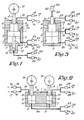
- FIG. 5 represents a double-acting dosing machine according to the invention.
- the metering device essentially consists of a body 1 containing, suitably, two combined pistons 2 -3, carrying on both sides a piston rod, respectively 4 and 5.
- the pistons 2 and 3 slide in bores, respectively 6 and 7, which form, so to speak, chambers, respectively 8 and 9, while the piston rods and / or guide rods 4 and 5 slide in passages, respectively 10 and 11, of the cylindrical body 1, of which, in this case, the bottom wall is, at the level of the piston rod 5, provided a dome-shaped extension 12 forming a chamber 13.
- a cam 14 or another similar control device cooperates, according to one of the characteristics of the invention, with the piston rod 4 for the control of the pistons 2 and 3.
- the chamber 8 is in communication by a pipe 15, on the one hand, with a water supply pipe 17 via a non-return valve 16 and, on the other hand, with a pipe evacuation of water 19 via a non-return valve 18.
- the chamber 9 communicates via a line 20, on the one hand, with an air supply line 22 via a valve 21 and, on the other hand, with an air discharge line 24 via a valve 23, while the chamber 13 communicates by a line 25, on the one hand, with a line of foaming liquid 27 via a non-return valve 26 and, on the other hand, with a foaming liquid discharge line 29 by through a pressure relief valve 28.
- the space 30, delimited by the upper face of the piston 3 and the upper wall of the bore 7, is, in this case, placed in communication with the external atmosphere by a pipe 31.
- the air introduced into the chamber 9 under a well-determined pressure also serves as an additional function, to ensure the upward movement of the system.
- FIG. 1 It is easy to see that the result, obtained with a device according to FIG. 1, is also obtained with a device of the kind illustrated by FIG. 2, comprising a body 1 provided with two separate bores 6 and 7, each provided with a piston , respectively 2 and 3, pistons which delimit above them a chamber, respectively 8 and 13, and below them spaces 9, placed in communication by line 20 and valves 21 and 23 respectively with a line air intake 22 and an air discharge pipe 24.
- each of the two pistons 2 and 3 is provided with a piston rod 4 with which a cam 14 cooperates.
- the chambers, respectively 8 and 13 are in communication with pipes 15 and 25.
- the volumes of the spaces 8, 9 and 13 are, as in the previous case, carefully calculated and mutually adapted to ensure a supply of water, air and liquid foaming agent dosed correctly with the foaming device, although this result can also be obtained by judicious adjustment of the piston strokes determined by the cams 14, which may have different dimensions mutually adjusted and be mounted on the same axis or on axes different.
- FIG. 3 represents an embodiment in which the pistons 2 and 3 are fixed to the piston rod 4 of a pneumatic cylinder 32, provided with inlet and outlet pipes 33-34 and appropriately controlled to replace both the control carried out by the air supply via line 20 as well as that carried out by means of a cam or other similar mechanical device.
- the space 9 located under the piston 3 communicates via a pipe 20 with an air supply pipe 22 and an air discharge pipe 24, while the spaces 13 and 8 located above pistons 2 and 3 are, as in the previous case, connected by lines 25 and 15 to supply and discharge devices respectively for the foaming liquid and the water.
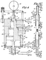
- FIG. 4 represents an installation based on the implementation of a device of the kind illustrated by FIG. 1, the cylindrical body 1 of which contains a piston composed of three separate parts with staggered diameters, 2, 35 and 3 respectively, the ends carry the piston rods 4 and 5, which, as in the previous example, slide in bores, respectively 10 and 11, while the pistons 2, 35 and 3 slide in bores, respectively 6, 36 and 7, for the formation of chambers 8, 37 and 9.
- the bottom of the apparatus which, in the present embodiment, is in the form of a cover 38, fixed to the body 1, by screws 40 with the intermediary of a sealing device, is provided with a dome 12 containing a chamber 13.
- the chambers 8, 9 and 13 are in communication via the lines 15, 20 and 25 with discharge lines by means of non-return valves and of valves, provided with the same reference numbers as those of the device represented in FIG. 1.
- the space 30, located above the piston 3, is also in communication with the atmosphere by a pipe 31.
- the space 37 is placed in communication by a line 41 and a valve 42 with the compressed air supply line 43, line 41 which is also connected by means of a valve 44 to a pipe 45 for the evacuation of this compressed air.
- the moving parts of the device are fitted with O-rings, the number of which is at least equal to that of these parts.
- the piston rod 4 carries an idler roller 47 at the top, which cooperates with the cam 14 and whose axis 48 is secured to a lever 49, on the one hand, articulated to the body 1 of the device by means of a pivot 50 and, on the other hand, with an adjustable position with an adjustment screw 51 for adjusting, on the one hand, the stroke of the pistons 2, 15 and 3 and on the other hand part, that of the piston rod 5 for adjusting the amount of foam formed per cycle of the device.
- FIG. 4 corresponds roughly to that of the device described with reference to FIG. 1, except for the fact that the compressed air supplied to the chamber 37 regulates the pressure exerted by the roller 47 on the cam 14 during the upward stroke controlled by the pressure prevailing in the chamber 9, in order to reduce the stress on the cam 14 as much as possible.
- this chamber 37 is not essential, but can be used in combination with the chamber 9 to adjust and modify the load by which the cam 14 is biased. It is easy to see that this result would also be obtained by not providing as the pistons 2 and 3 and by using the chamber 30 only for the supply of compressed air.
- FIG. 5 represents an embodiment of a double-acting dosing device according to the invention.
- This device consists of two devices of the kind previously described, mounted coaxially in series, the piston rods 4 of which are coupled by an adjustment rod 52 for adjusting the flow rate.
- the present embodiment is distinguished by the fact that the air supply is also used to control the metering device by means of a appropriate design of his order.
- the pressure of the compressed air supplied to the metering device according to the invention must be carefully adjusted, for example using an ordinary pressure regulator, in order to ensure effective foaming, duly adjusted.
- the implementation of the system according to the invention gives an apparatus that is as simple as it is efficient, of a relatively low cost price and of great reliability, and which is distinguished by a high dosing precision. .
- control of the metering device according to the invention can also be either entirely pneumatic in nature, as described for example for the embodiment illustrated in FIG. 3, or entirely mechanical, for example in the form of a positive cam control.
Abstract
Description
La présente invention a trait à un dispositif de dosage ou doseuse, à savoir, en particulier, à un dispositif servant à assurer, lors de la préparation d'un mortier-mousse, tel qu'un mortier dit cellulaire, qu'une quantité déterminée de mousse, proportionnelle à la quantité de mortier proprement dit, est introduite dans le malaxeur de mortier.The present invention relates to a metering or dosing device, namely, in particular, to a device used to ensure, during the preparation of a foam mortar, such as a so-called cellular mortar, that a determined quantity foam, proportional to the quantity of mortar proper, is introduced into the mortar mixer.
L'objet principal de l'invention est la réalisation d'une doseuse de ce genre, qui se prête, de manière automatique et des plus simples et efficaces, au dosage spécifié ci-dessus, et cela de manière que les quantités requises de liquide moussant, d'eau et d'air, débitées par la doseuse selon l'invention, sont introduites dans un dispositif connu en soi, où le mélange de liquide moussant, d'eau et d'air est transformé en mousse, qui est ensuite introduite dans ledit malaxeur.The main object of the invention is the production of a dosing device of this kind, which lends itself, automatically and most simply and efficiently, to the dosage specified above, and in such a way that the required quantities of liquid foaming agent, water and air, delivered by the metering device according to the invention, are introduced into a device known per se, where the mixture of foaming liquid, water and air is transformed into foam, which is then introduced into said mixer.
La doseuse selon l'invention se compose principalement de deux pistons, qui délimitent ensemble au moins trois chambres pour le dosage respectivement d'eau, d'air et de liquide moussant dans une proportion bien déterminée.The metering device according to the invention mainly consists of two pistons, which together delimit at least three chambers for the metering respectively of water, air and foaming liquid in a well determined proportion.
Les caractéristiques et avantages de l'invention ressortiront plus clairement de la description détaillée suivante de quelques modes de mise en oeuvre préférés, décrits à titre d'exemples sans la moindre intention restrictive avec référence aux dessins annexés, où la figure 1 représente en coupe verticale schématique un mode d'exécution de la doseuse selon l'invention; les figures 2 à 4 représentent de manière schématique des variantes du mode d'exécution illustré par la figure 1; et la figure 5 représente une doseuse à double effet selon l'invention.The characteristics and advantages of the invention will emerge more clearly from the following detailed description of some preferred embodiments, described by way of examples without any restrictive intention with reference to the appended drawings, where Figure 1 shows in schematic vertical section an embodiment of the metering device according to the invention; Figures 2 to 4 schematically show variants of the embodiment illustrated in Figure 1; and FIG. 5 represents a double-acting dosing machine according to the invention.
Comme on le voit en se reportant à la figure 1, qui représente un mode de mise en oeuvre des plus simples, le dispositif de dosage selon l'invention se compose essentiellement d'un corps 1 contenant, de manière appropriée, deux pistons combinés 2-3, portant de part et d'autre une tige de piston, respectivement 4 et 5. Les pistons 2 et 3 coulissent en des alésages, respectivement 6 et 7, qui forment pour ainsi dire des chambres, respectivement 8 et 9, tandis que les tiges de piston et/ou tiges de guidage 4 et 5 coulissent en des passages, respectivement 10 et 11, du corps cylindrique 1, dont, en l'occurrence, la paroi inférieure est, au niveau de la tige de piston 5, munie d'un prolongement en forme de dôme 12 formant une chambre 13.As can be seen with reference to FIG. 1, which represents a simplest embodiment, the metering device according to the invention essentially consists of a
Une came 14 ou un autre dispositif de commande analogue coopère, suivant une des caractéristiques de l'invention, avec la tige de piston 4 en vue de la commande des pistons 2 et 3.A
La chambre 8 se trouve en communication par une conduite 15, d'une part, avec une conduite d'amenée d'eau 17 par l'entremise d'une soupape de non-retour 16 et, d'autre part, avec une conduite d'évacuation d'eau 19 par l'entremise d'une soupape de non-retour 18. La chambre 9 communique par une conduite 20, d'une part, avec une conduite d'amenée d'air 22 par l'entremise d'une soupape 21 et, d'autre part, avec une conduite d'évacuation d'air 24 par l'entremise d'une soupape 23, tandis que la chambre 13 communique par une conduite 25, d'une part, avec une conduite d'amenée de liquide moussant 27 par l'entremise d'une soupape de non-retour 26 et, d'autre part, avec une conduite d'évacuation de liquide moussant 29 par l'entremise d'une soupape à surpression 28.The
Enfin, l'espace 30, délimité par la face supérieure du piston 3 et la paroi supérieure de l'alésage 7, est, en l'occurrence, mis en communication avec l'atmosphère extérieure par une conduite 31.Finally, the
Le fonctionnement du dispositif décrit dans les lignes précédentes est des plus simples.The operation of the device described in the preceding lines is very simple.
En effet, il suffit de calculer le volume des chambres 8, 9 et 13 de manière que le déplacement du piston commandé par ladite came 14, se prête à l'amenée dans l'appareil de quantités déterminées d'eau, d'air et de liquide moussant et à l'évacuation de quantités déterminées d'eau, d'air et de liquide moussant, par coup, le retour de ces fluides vers les conduites d'amenée 17, 22 et 27 étant évité par les soupapes de non-retour 16 et 26 et la soupape 21, de manière à assurer leur introduction dans un dispositif de moussage par les conduites 19, 24 et 29 et la soupape de non-retour 18, la soupape 23 et la soupape à surpression 28, soupapes 18, 23 et 28 qui servent à empêcher à coup sûr tout retour vers les chambres 8, 9 et 13 des liquides et de l'air ainsi évacués.Indeed, it suffices to calculate the volume of the
Dans ce mode de mise en oeuvre du système selon l'invention, l'air introduit dans la chambre 9 sous une pression bien déterminée, sert également à titre de fonction supplémentaire, à assurer le mouvement ascendant du système.In this embodiment of the system according to the invention, the air introduced into the
On voit facilement que le résultat, obtenu avec un dispositif selon la figure 1, s'obtient également avec un dispositif du genre illustré par la figure 2, comportant un corps 1 muni de deux alésages séparés 6 et 7, munis chacun d'un piston, respectivement 2 et 3, pistons qui délimitent au-dessus d'eux une chambre, respectivement 8 et 13, et en dessous d'eux des esapces 9, mis en communication par la conduite 20 et les soupapes 21 et 23 respectivement avec une conduite d'amenée d'air 22 et une conduite d'évacuation d'air 24.It is easy to see that the result, obtained with a device according to FIG. 1, is also obtained with a device of the kind illustrated by FIG. 2, comprising a
Dans ce cas, chacun des deux pistons 2 et 3 est muni d'une tige de piston 4 avec laquelle coopère une came 14.In this case, each of the two
Comme dans le cas précédent, les chambres, respectivement 8 et 13, se trouvent en communication avec des conduites 15 et 25.As in the previous case, the chambers, respectively 8 and 13, are in communication with
Il va sans dire que, dans ce deuxième mode d'exécution, les volumes des espaces 8, 9 et 13 sont, comme dans le cas précédent, soigneusement calculés et mutuellement adaptés pour assurer une alimentation d'eau, d'air et de liquide moussant dûment dosée du dispositif de moussage, bien que ce résultat puisse également s'obtenir par un réglage judicieux des courses des pistons déterminées par les cames 14, qui pourront avoir des dimensions différentes mutuellement réglées et être montées sur le même axe ou sur des axes différents.It goes without saying that, in this second embodiment, the volumes of the
La figure 3 représente un mode d'exécution dans lequel les pistons 2 et 3 sont fixés à la tige de piston 4 d'un cylindre pneumatique 32, muni de conduites d'entrée et de sortie 33-34 et commandé de manière appropriée pour remplacer aussi bien la commande réalisée par l'amenée d'air par la conduite 20 que celle effectuée au moyen d'une came ou d'un autre dispositif mécanique analogue.FIG. 3 represents an embodiment in which the
Dans ce cas, l'espace 9 situé sous le piston 3 communique par une conduite 20 avec une conduite d'amenée d'air 22 et une conduite d'évacuation d'air 24, tandis que les espaces 13 et 8 situés au-dessus des pistons 2 et 3 sont, comme dans le cas précédent, reliés par des conduites 25 et 15 à des dispositifs d'amenée et d'évacuation respectivement pour le liquide moussant et l'eau.In this case, the
La figure 4 représente une installation basée sur la mise en oeuvre d'un dispositif du genre illustré par la figure 1, dont le corps cylindrique 1 contient un piston composé de trois parties séparées à diamètres échelonnés, respectivement 2, 35 et 3, dont les extrémités portent les tiges de piston 4 et 5, qui, comme dans l'exemple précédent, coulissent en des alésages, respectivement 10 et 11, tandis que les pistons 2, 35 et 3 coulissent en des alésages, respectivement 6, 36 et 7, en vue de la formation de chambres 8, 37 et 9.FIG. 4 represents an installation based on the implementation of a device of the kind illustrated by FIG. 1, the
Le fond de l'appareil, qui, dans le présent mode d'exécution, se présente sous forme d'un couvercle 38, fixé au corps 1, par des vis 40 avec entremise d'un dispositif d'étanchéité, est muni d'un dôme 12 contenant une chambre 13.The bottom of the apparatus, which, in the present embodiment, is in the form of a
Comme dans l'exemple illustré par la figure 1, les chambres 8, 9 et 13 se trouvent en communication par les conduites 15, 20 et 25 avec des conduites d'évacuation par l'entremise de soupapes de non-retour et de soupapes, munies des mêmes chiffres de référence que celles du dispositif représenté par la figure 1. L'espace 30, situé au-dessus du piston 3, se trouve également en communication avec l'atmosphère par une conduite 31.As in the example illustrated in FIG. 1, the
Dans ce mode d'exécution, l'espace 37 est mis en communication par une conduite 41 et une soupape 42 avec la conduite d'amenée d'air comprimé 43, conduite 41 qui est également connectée par l'entremise d'une soupape 44 à une conduite 45 pour l'évacuation de cet air comprimé.In this embodiment, the
Les parties mobiles de l'appareil sont munies de joint toriques, dont le nombre est au moins égal à celui de ces parties.The moving parts of the device are fitted with O-rings, the number of which is at least equal to that of these parts.
Selon le présent mode d'exécution de l'invention, la tige de piston 4 porte en haut un galet fou 47, qui coopère avec la came 14 et dont l'axe 48 est solidaire d'un levier 49, d'une part, articulé au corps 1 du dispositif au moyen d'un pivot 50 et, d'autre part, à position réglable avec une vis de réglage 51 pour régler, d'une part, la course des pistons 2, 15 et 3 et d'autre part, celle de la tige de piston 5 en vue du réglage de la quantité de mousse formée par cycle du dispositif.According to this embodiment of the invention, the
Le fonctionnement du dispositif illustré par la figure 4 correspond à peu près à celui du dispositif décrit avec référence à la figure 1, à part le fait que l'air comprimé amené vers la chambre 37 assure le réglage de la pression exercée par le galet 47 sur la came 14 pendant la course ascendante commandée par la pression régnant dans la chambre 9, pour réduire autant que possible la sollicitation de la came 14.The operation of the device illustrated in FIG. 4 corresponds roughly to that of the device described with reference to FIG. 1, except for the fact that the compressed air supplied to the
Il est évident que cette chambre 37 n'est pas indispensable, mais peut être employée en combinaison avec la chambre 9 pour régler et modifier la charge par laquelle est sollicitée la came 14. On voit facilement que ce résultat s'obtiendrait également en ne prévoyant que les pistons 2 et 3 et en employant la chambre 30 uniquement pour l'amenée d'air comprimé.It is obvious that this
La figure 5 représente un mode d'exécution d'un dispositif de dosage à double effet selon l'invention. Ce dispositif se compose de deux dispositifs du genre précédemment décrit montés coaxialement en série, dont les tiges de piston 4 sont accouplées par une tige de réglage 52 en vue du réglage du débit.FIG. 5 represents an embodiment of a double-acting dosing device according to the invention. This device consists of two devices of the kind previously described, mounted coaxially in series, the
Bien que les caractéristiques et le fonctionnement soient les mêmes que ceux du mode d'exécution précédemment décrit, le présent mode d'exécution se distingue par le fait que l'amenée d'air sert également à la commande du dispositif de dosage grâce à une conception appropriée de sa commande.Although the characteristics and the operation are the same as those of the embodiment described above, the present embodiment is distinguished by the fact that the air supply is also used to control the metering device by means of a appropriate design of his order.
Il va sans dire qu'on s'efforcera de faire, au préalable, un choix optimal des proportions volumétriques entre les différentes chambres.It goes without saying that we will endeavor to make, beforehand, an optimal choice of the volumetric proportions between the different rooms.
Par suite des différences de concentration inévitables entre les liquides moussants de différentes provenances, il y a lieu de prévoir un système de réglage supplémentaire, assurant l'amenée à ladite chambre 13 de liquide moussant dilué ou non avec une dose appropriée d'eau pour réaliser ainsi au préalable un réglage judicieux en fonction du rapport volumétrique entre les chambres 8 et 13.As a result of the inevitable concentration differences between the foaming liquids of different origins, it is necessary to provide an additional adjustment system, ensuring the supply to said
La pression de l'air comprimé amené vers la doseuse selon l'invention devra être soigneusement réglée par exemple à l'aide d'un régulateur de pression ordinaire, dans le but d'assurer un moussage efficace, dûment réglé.The pressure of the compressed air supplied to the metering device according to the invention must be carefully adjusted, for example using an ordinary pressure regulator, in order to ensure effective foaming, duly adjusted.
On voit de ce qui précède que la mise en oeuvre du système selon l'invention donne un appareil aussi simple qu'efficace, d'un prix de revient relativement bas et d'une grande fiabilité, et se distinguant par une grande précision de dosage.It can be seen from the above that the implementation of the system according to the invention gives an apparatus that is as simple as it is efficient, of a relatively low cost price and of great reliability, and which is distinguished by a high dosing precision. .
Bien que dans les exemples illustrés par les figures 1, 2 et 4 soit prévue une commande mécanique, d'une part, et pneumatique, d'autre part, il va sans dire que la commande de la doseuse selon l'invention pourra également être soit intégralement de nature pneumatique, à la manière décrite par exemple pour le mode d'exécution illustré par la figure 3, soit intégralement mécanique, par exemple sous forme d'une commande positive à came.Although in the examples illustrated in FIGS. 1, 2 and 4 there is provided a mechanical control, on the one hand, and pneumatic control, on the other hand, it goes without saying that the control of the metering device according to the invention can also be either entirely pneumatic in nature, as described for example for the embodiment illustrated in FIG. 3, or entirely mechanical, for example in the form of a positive cam control.
Il va de soi que l'invention ne se limite pas aux exemples d'exécution décrits dans les lignes précédentes et illustrés par les figures annexées, mais en prévoit toutes sortes de modifications, d'additions et d'adaptations en ce qui concerne les formes et dimensions, évidemment à condition de ne pas dépasser son cadre défini dans les revendications formulées ci-après.It goes without saying that the invention is not limited to the exemplary embodiments described in the preceding lines and illustrated by the appended figures, but provides for all kinds of modifications, additions and adaptations as regards the forms. and dimensions, obviously provided that it does not exceed its framework defined in the claims formulated below.
Claims (18)
Priority Applications (1)
| Application Number | Priority Date | Filing Date | Title |
|---|---|---|---|
| AT83201688T ATE44257T1 (en) | 1982-12-02 | 1983-11-29 | DOSING DEVICE. |
Applications Claiming Priority (2)
| Application Number | Priority Date | Filing Date | Title |
|---|---|---|---|
| BE895216 | 1982-12-02 | ||
| BE895216 | 1982-12-02 |
Publications (3)
| Publication Number | Publication Date |
|---|---|
| EP0113486A2 true EP0113486A2 (en) | 1984-07-18 |
| EP0113486A3 EP0113486A3 (en) | 1985-05-22 |
| EP0113486B1 EP0113486B1 (en) | 1989-06-28 |
Family
ID=3862033
Family Applications (1)
| Application Number | Title | Priority Date | Filing Date |
|---|---|---|---|
| EP83201688A Expired EP0113486B1 (en) | 1982-12-02 | 1983-11-29 | Proportioning device |
Country Status (3)
| Country | Link |
|---|---|
| EP (1) | EP0113486B1 (en) |
| AT (1) | ATE44257T1 (en) |
| DE (1) | DE3380118D1 (en) |
Cited By (4)
| Publication number | Priority date | Publication date | Assignee | Title |
|---|---|---|---|---|
| DE3630992A1 (en) * | 1986-09-11 | 1988-03-17 | Siemens Ag | Apparatus for metering and mixing materials |
| EP0466772A1 (en) * | 1989-03-31 | 1992-01-22 | Fountain Fresh, Inc. | Methods and apparatus for dispensing plural fluids in a precise proportion |
| US5388725A (en) * | 1993-11-24 | 1995-02-14 | Fountain Fresh International | Fluid-driven apparatus for dispensing plural fluids in a precise proportion |
| CN102213205A (en) * | 2011-06-03 | 2011-10-12 | 杭州佳湖科技有限公司 | Reciprocating type double-acting gas-liquid multiphase pump with three cylinders |
Citations (5)
| Publication number | Priority date | Publication date | Assignee | Title |
|---|---|---|---|---|
| FR2168542A1 (en) * | 1972-01-19 | 1973-08-31 | Alfa Laval Ab | |
| FR2194473A2 (en) * | 1972-07-28 | 1974-03-01 | Usm Corp | |
| FR2246169A5 (en) * | 1973-10-01 | 1975-04-25 | Leandri Luigi | Foamed concrete mix producer - has volumetric pumps beneath the site surface, with foam-forming sling and collector |
| US3926345A (en) * | 1972-02-03 | 1975-12-16 | Stabilator Ab | Device for the batching of media |
| FR2389404A1 (en) * | 1977-05-04 | 1978-12-01 | Baldwin Gegenheimer Corp |
Family Cites Families (1)
| Publication number | Priority date | Publication date | Assignee | Title |
|---|---|---|---|---|
| BE895216A (en) * | 1982-12-02 | 1983-03-31 | Neuckens Francois | Dosimeter used in prodn. of cellular material - has cam-driven stepped piston assembly for simultaneous metering of water, air and foaming agent |
-
1983
- 1983-11-29 EP EP83201688A patent/EP0113486B1/en not_active Expired
- 1983-11-29 AT AT83201688T patent/ATE44257T1/en not_active IP Right Cessation
- 1983-11-29 DE DE8383201688T patent/DE3380118D1/en not_active Expired
Patent Citations (5)
| Publication number | Priority date | Publication date | Assignee | Title |
|---|---|---|---|---|
| FR2168542A1 (en) * | 1972-01-19 | 1973-08-31 | Alfa Laval Ab | |
| US3926345A (en) * | 1972-02-03 | 1975-12-16 | Stabilator Ab | Device for the batching of media |
| FR2194473A2 (en) * | 1972-07-28 | 1974-03-01 | Usm Corp | |
| FR2246169A5 (en) * | 1973-10-01 | 1975-04-25 | Leandri Luigi | Foamed concrete mix producer - has volumetric pumps beneath the site surface, with foam-forming sling and collector |
| FR2389404A1 (en) * | 1977-05-04 | 1978-12-01 | Baldwin Gegenheimer Corp |
Cited By (5)
| Publication number | Priority date | Publication date | Assignee | Title |
|---|---|---|---|---|
| DE3630992A1 (en) * | 1986-09-11 | 1988-03-17 | Siemens Ag | Apparatus for metering and mixing materials |
| EP0466772A1 (en) * | 1989-03-31 | 1992-01-22 | Fountain Fresh, Inc. | Methods and apparatus for dispensing plural fluids in a precise proportion |
| EP0466772A4 (en) * | 1989-03-31 | 1992-03-25 | Fountain Fresh, Inc. | Methods and apparatus for dispensing plural fluids in a precise proportion |
| US5388725A (en) * | 1993-11-24 | 1995-02-14 | Fountain Fresh International | Fluid-driven apparatus for dispensing plural fluids in a precise proportion |
| CN102213205A (en) * | 2011-06-03 | 2011-10-12 | 杭州佳湖科技有限公司 | Reciprocating type double-acting gas-liquid multiphase pump with three cylinders |
Also Published As
| Publication number | Publication date |
|---|---|
| EP0113486A3 (en) | 1985-05-22 |
| EP0113486B1 (en) | 1989-06-28 |
| DE3380118D1 (en) | 1989-08-03 |
| ATE44257T1 (en) | 1989-07-15 |
Similar Documents
| Publication | Publication Date | Title |
|---|---|---|
| EP0113486A2 (en) | Proportioning device | |
| FR2802250A3 (en) | Hydraulic power converter consists of main oil tank, hydraulic pumps, motor, and two-circuit hydraulic cylinder mechanism | |
| FR2567578A1 (en) | LIQUID FUEL PUMP APPARATUS FOR INTERNAL COMBUSTION ENGINE | |
| WO1987007352A1 (en) | Liquid distribution valve | |
| FR2465902A1 (en) | MEMBRANE PUMP FOR DETERMINING TWO COMPONENTS OF A MIXTURE AND PUMP ASSEMBLY COMPRISING TWO PUMPS | |
| FR2783514A3 (en) | Rapid acting hydraulic unit, for use in jack, has three concentric cylindrical oil chambers, with innermost chamber containing drift, fixed to base to allow oil through to operate main stem | |
| FR2493407A1 (en) | PUMPING APPARATUS FOR FUEL INJECTION | |
| FR2681646A1 (en) | Pump including a metering system, and device including such a pump, for injecting an additive into a main liquid | |
| FR2559841A1 (en) | INJECTION DEVICE FOR TWO-STROKE ENGINES | |
| FR2613782A1 (en) | Metering pump with a spool | |
| FR2582734A1 (en) | FUEL INJECTION PUMP | |
| FR2544396A1 (en) | FUEL INJECTOR | |
| CH657668A5 (en) | FLUID PUMP. | |
| FR2475129A1 (en) | INJECTION PUMP APPARATUS FOR INTERNAL COMBUSTION ENGINE | |
| EP0172076A1 (en) | Metering-dosing device for fluids | |
| FR2487011A1 (en) | LIQUID FUEL INJECTION PUMP | |
| FR2682162A1 (en) | RADIAL PISTON PUMP. | |
| EP0072269B1 (en) | Fuel injector, especially for an internal-combustion engine | |
| FR2503418A1 (en) | DEVICE FOR PROGRAMMING THE COMPOSITION OF A LIQUID, IN PARTICULAR FOR LIQUID-PHASE CHROMATOGRAPHY | |
| CH274188A (en) | Dispensing device for carbonated mixed drinks. | |
| CH657669A5 (en) | FLUID PUMP. | |
| FR2551137A1 (en) | FUEL INJECTOR | |
| CH340092A (en) | Piston injection pump | |
| CH579749A5 (en) | Liquid additive dispensing pump - twin pistons compress bellows to force oil from compression chambers to injection nozzle | |
| FR2668207A1 (en) | Metering pump with controlled plug |
Legal Events
| Date | Code | Title | Description |
|---|---|---|---|
| PUAI | Public reference made under article 153(3) epc to a published international application that has entered the european phase |
Free format text: ORIGINAL CODE: 0009012 |
|
| AK | Designated contracting states |
Designated state(s): AT CH DE FR GB IT LI LU NL SE |
|
| PUAL | Search report despatched |
Free format text: ORIGINAL CODE: 0009013 |
|
| AK | Designated contracting states |
Designated state(s): AT CH DE FR GB IT LI LU NL SE |
|
| 17P | Request for examination filed |
Effective date: 19851121 |
|
| 17Q | First examination report despatched |
Effective date: 19870612 |
|
| D17Q | First examination report despatched (deleted) | ||
| GRAA | (expected) grant |
Free format text: ORIGINAL CODE: 0009210 |
|
| AK | Designated contracting states |
Kind code of ref document: B1 Designated state(s): AT CH DE FR GB IT LI LU NL SE |
|
| PG25 | Lapsed in a contracting state [announced via postgrant information from national office to epo] |
Ref country code: SE Effective date: 19890628 Ref country code: AT Effective date: 19890628 |
|
| REF | Corresponds to: |
Ref document number: 44257 Country of ref document: AT Date of ref document: 19890715 Kind code of ref document: T |
|
| GBT | Gb: translation of ep patent filed (gb section 77(6)(a)/1977) | ||
| REF | Corresponds to: |
Ref document number: 3380118 Country of ref document: DE Date of ref document: 19890803 |
|
| ITF | It: translation for a ep patent filed |
Owner name: BARZANO'E ZANARDO S.P.A. |
|
| PLBE | No opposition filed within time limit |
Free format text: ORIGINAL CODE: 0009261 |
|
| STAA | Information on the status of an ep patent application or granted ep patent |
Free format text: STATUS: NO OPPOSITION FILED WITHIN TIME LIMIT |
|
| 26N | No opposition filed | ||
| PGFP | Annual fee paid to national office [announced via postgrant information from national office to epo] |
Ref country code: GB Payment date: 19911129 Year of fee payment: 9 |
|
| ITTA | It: last paid annual fee | ||
| PGFP | Annual fee paid to national office [announced via postgrant information from national office to epo] |
Ref country code: CH Payment date: 19920110 Year of fee payment: 9 |
|
| PG25 | Lapsed in a contracting state [announced via postgrant information from national office to epo] |
Ref country code: GB Effective date: 19921129 |
|
| PG25 | Lapsed in a contracting state [announced via postgrant information from national office to epo] |
Ref country code: LI Effective date: 19921130 Ref country code: CH Effective date: 19921130 |
|
| GBPC | Gb: european patent ceased through non-payment of renewal fee |
Effective date: 19921129 |
|
| REG | Reference to a national code |
Ref country code: CH Ref legal event code: PL |
|
| PGFP | Annual fee paid to national office [announced via postgrant information from national office to epo] |
Ref country code: DE Payment date: 19940124 Year of fee payment: 11 |
|
| EPTA | Lu: last paid annual fee | ||
| PGFP | Annual fee paid to national office [announced via postgrant information from national office to epo] |
Ref country code: FR Payment date: 19941130 Year of fee payment: 12 |
|
| PG25 | Lapsed in a contracting state [announced via postgrant information from national office to epo] |
Ref country code: DE Effective date: 19950801 |
|
| PG25 | Lapsed in a contracting state [announced via postgrant information from national office to epo] |
Ref country code: FR Effective date: 19960731 |
|
| REG | Reference to a national code |
Ref country code: FR Ref legal event code: ST |
|
| PG25 | Lapsed in a contracting state [announced via postgrant information from national office to epo] |
Ref country code: LU Free format text: LAPSE BECAUSE OF NON-PAYMENT OF DUE FEES Effective date: 20001129 |
|
| PGFP | Annual fee paid to national office [announced via postgrant information from national office to epo] |
Ref country code: NL Payment date: 20021130 Year of fee payment: 20 |
|
| PGFP | Annual fee paid to national office [announced via postgrant information from national office to epo] |
Ref country code: LU Payment date: 20030102 Year of fee payment: 18 |
|
| PG25 | Lapsed in a contracting state [announced via postgrant information from national office to epo] |
Ref country code: NL Free format text: LAPSE BECAUSE OF EXPIRATION OF PROTECTION Effective date: 20031129 |
|
| NLV7 | Nl: ceased due to reaching the maximum lifetime of a patent |
Effective date: 20031129 |