EP0113272A1 - Modular nodal communication network - Google Patents
Modular nodal communication network Download PDFInfo
- Publication number
- EP0113272A1 EP0113272A1 EP19830402420 EP83402420A EP0113272A1 EP 0113272 A1 EP0113272 A1 EP 0113272A1 EP 19830402420 EP19830402420 EP 19830402420 EP 83402420 A EP83402420 A EP 83402420A EP 0113272 A1 EP0113272 A1 EP 0113272A1
- Authority
- EP
- European Patent Office
- Prior art keywords
- module
- node
- connection
- routing
- nodes
- Prior art date
- Legal status (The legal status is an assumption and is not a legal conclusion. Google has not performed a legal analysis and makes no representation as to the accuracy of the status listed.)
- Granted
Links
Images


Classifications
-
- H—ELECTRICITY
- H04—ELECTRIC COMMUNICATION TECHNIQUE
- H04Q—SELECTING
- H04Q3/00—Selecting arrangements
- H04Q3/64—Distributing or queueing
- H04Q3/68—Grouping or interlacing selector groups or stages
Definitions
- the present invention relates to a modular mesh communications network.
- a network is intended to ensure data exchanges between equipment, or systems in particular in the case of a data processing system with distributed architecture.
- a modular communications network pertaining to the prior art is described in French patent 2,366,754 entitled modular switching network.
- Such a network is constituted by elementary switching assemblies all identical connected together according to a mesh network, and grouped in such a way that the connections are made according to a first law within a group and according to a second law of group to group.
- This way of doing things has a certain number of drawbacks, such as the non-adaptability of the network to the internal architecture of a building in which it is located, making it complex and the relatively considerable degradation of the transmission in the event of a failure.
- an elementary switching set mainly if the network is not sufficiently redundant.
- the invention is aimed at a mesh network which does not have the drawbacks mentioned above.
- the network according to the invention ensures the exchange of data between two terminal devices which are connected to it in a self-adapting manner, that is to say that the connection of a terminal equipment called caller to the equipment said recipient terminal is carried out step by step from one connection node to another of the network through data transmission conduits which connect them.
- each node which according to the invention is connected to a certain number of other nodes of the network, includes means which enable it to search for an adjacent node by means of which it can advance the connection which is at establish between the requesting and receiving terminals.
- the invention thus also relates to the definition of a self-adapting node of a modular mesh network.
- a modular mesh communications network for establishing communications between devices capable of transmitting or receiving information, said network comprising connection nodes and information transmission conduits connecting the nodes between them; the devices being connected to terminals, themselves connected to the nodes, each node (N) being connected to a defined number of other nodes by conduits, each node comprising an equal number of incoming (LE) and outgoing (LS) lines and means ensuring simultaneous and independent switching, and logic means making it possible, from the node to which the connection has been reached, to seek and then continue the connection with an adjacent node, this operation being repeated step by step from one node to the next until a connection is established between two terminals connected respectively to the devices to be connected.
- L incoming
- LS outgoing
- the object of the invention is to define a modular mesh communications network, which are transparent in use, which allows several simultaneous high-speed links, which is not very vulnerable and reconfigurable in the event of failure or partial destruction.
- the system mainly comprises, on the one hand, connection nodes and conduits, ensuring the transmission of information between the nodes, and, on the other hand, terminal devices, connected by conduits to the network nodes and to the equipment and information transmitting and receiving systems, hereinafter called "devices", the terminals forming an interface between the network and the devices.
- devices equipment and information transmitting and receiving systems
- a disconnect command issued by a terminal enables the link to be broken and all the components of the link to be released.
- the network according to the invention being with distributed command and control, the establishment of a connection, as has also been reported, is done step by step, from one node to an adjacent node.
- a node must therefore include means enabling it to find a free path to an adjacent node to advance the connection step by step and to protect it from a failure of a centralized device, a path that can generally always to be found bound for one of the adjacent nodes of the node considered, each node being connected to a determined finite number of other nodes.
- Figure 1 gives a very simple representation of the network according to the invention. This consists of a geographically bounded set, the maximum dimensions of which depend on the applications. Depending on the requested transport capacity, the number N of network nodes can vary from a few units to several hundred. These nodes are linked together by conduits capable of transporting information in both directions.
- the network being three-dimensional, the nodes are defined by three coordinates, for example IJK, MNP, QRS, TUV.
- FIG. 1 schematically represents devices (equipment, sub-systems or systems At, Ax, Al, A2, A3 which must exchange data across the network according to the invention. These devices are therefore connected to specific equipment called terminals and identified T.
- RE designates the network proper, constituted by the nodes N and their interconnection conduits
- the terminals T which must carry out the concentration of data coming from the devices and the interface between the devices and the network, have similarities with the nodes and although external to the RE network proper, they are connected to it by bidirectional links available in each node.
- a terminal T can thus be placed anywhere in the network and, like a node, it is defined by three coordinates (1, J, K) for example.
- any "network" input-output of a terminal can be linked to any input-output of a node.
- the number of inputs-outputs of the terminals and of the nodes is equal to eight.
- a terminal T (IJK) called the sending or requesting terminal, implements the procedure aimed at establishing a connection between devices, A1 and A3 for example.
- a connection is established between the requesting terminal T (IJK) and the destination terminal T (QRS), or requested terminal, to which the other is connected.
- A3 device Via this connection, bidirectional and simultaneous in the general case, the device A1 transmits directives to the terminal T (IJK) written according to an appropriate grammar, syntax and semantics, which contain the order given to the terminal T (IJK ) establish a connection between A1 and A3.
- the connections are predetermined in the terminals, it is the latter which take the initiative in transmitting the directives.
- FIG. 2 gives an example of words used by the network according to the invention to control a connection and the modifications which it undergoes as and when a node reached by the connection searches for an adjacent node. Also shown in this figure 2 is a connection word. These words are the words of the specific vocabulary of the network which are associated with the so-called information words.
- connection words MC the partial disconnection words MDP and the release words ML.
- Each word comprises in the example of FIG. 2, four fields.
- the connection word MC the first CH field, 3-bit indicates that the word is a network word; the second CO field represents a code indicating that it is a connection; the third field ADT represents the address of the destination terminal, which comprises 12 bits; the fourth field ADD represents the address of the last node reached by the route, it also includes 12 bits. As the route is established through the network, this field is modified.
- a partial disconnection word MDP has a format similar to that of the connection word, but the second COI field represents a code indicating a partial disconnection.
- a release word ML has a format similar to the previous one but the second field C02 represents a code indicating a release.
- FIG. 3 represents the main element of a node, in the symbolic and simplified form of a square matrix grid symbolizing a multiselector MS with 8 incoming links LE and 8 outgoing links LS.
- the crossings of the normally insulating meshes can by external commands become conductors of the signal coming from the incoming link in the direction of the outgoing link.
- the signals passing through the multiselectors of the nodes being binary, the crossing points can be assimilated to "AND" logic circuits with two inputs and one output, marked D1, D2.
- a marker M which as will be seen later is a memory, carries and maintains the logic signal "1", the circuit "AND”, D1 for example, placed at the geographical crossing of the conduits LE (3) and LS (4), effectively leads to the output terminal S4 any signal with the same electrical definition as that from the marker M.
- Figure 4 shows schematically how the mechanism for creating a route established by the signals exchanged between two devices is established, once the connection is completely established and validated between the devices A1 and A3, respectively connected to the requesting terminal T (001) and to the destination terminal T (632).
- appropriate circuits as will be explained later, execute a routing algorithm based on the connection word, which tends to cause the mesh to be chosen which, if available, most closely matches the destination terminal.
- the requesting terminal transmits to the node N (011) a connection message, as shown in FIG. 2, comprising in particular the address of the destination terminal, the address of the entity which transmits the word connection, here therefore the address of the requesting terminal T (001).
- the node N (011) executes the same algorithm, following which the conduit C (111, 011), that is to say the mesh connecting the nodes N (011) and N (111) is chosen .
- This selection process is repeated gradually until the arrival at the destination terminal T (6, 3, 2) after which the two terminals are joined by a simultaneous two-way link.
- the routing algorithm is implemented by logic circuits forming part of the node which has just been reached by a route being formed.
- the database from which this algorithm is executed is made up of the list of outgoing links from this node already part of a route and it goes without saying that the release of a connection using this route results in the corresponding deletion in this list.
- the node in question is called the provisional termination node, the others being part of the same route, transit nodes.
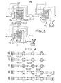
- FIG. 5 schematically represents a network of 64 nodes, of degree 4, homogeneous, complete and closed and by way of example, it is assumed that a route must be traced from node N (1; 3) (point A) to node N (6; 5) (point B) in the absence of any obstacle.
- the routing algorithm is started again from the representation of B by the coordinates (6; 5).
- the modulo 8 representation chosen of the destination node will be that for which the distance will be minimum.
- a route is constructed between the sending terminal and the destination terminal under the joint action of the routing algorithm which has been defined and the multiselectors of the nodes of which a description has been given.
- This action is initialized from the sending terminal as already said by connection words of n bits, specific in format, syntax and semantics of the connection function and a route is gradually formed by concatenation of bidirectional conduits joining a node to its neighbors, the number of which never exceeds 8 in the example described.
- concatenation is meant the process of forming a chain or route using successive meshes or conduits.
- a conduit is thus taken only if it is not used by a communication in progress, which is indicated by a storage register.
- the socket is accompanied by a test of the condition of the conduit and of the nodes on both sides.
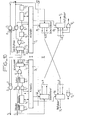
- the multiselectors MS1 of the node N (212), MS2 of the node N (222) and MS3 of the node N (322) are in so-called rest positions when all of their diagonal crossing points , and only them, are active. If this is the case for all multiselectors, both those of the nodes and those of the terminals, the network itself is said to be in the rest position.
- the multiselector for which all the crosspoints are inactive is said to be inactive and the same is true for the network when all of its multiselectors are inactive. It will be noted that all the activated cross points are indicated by a small black circle when they are diagonal, by circles of larger dimension when they are not. Also shown in this figure the conduits C (2,1,1); C (2,1,2) and C (2,2,2) using the bidirectional links between the nodes.
- Each mesh is made of two conduits, one for each direction.
- the process of tracing a route comes down to successive concatenations of internodal meshes with the already traced route, which is itself formed of meshes from the requesting terminal to the destination terminal.
- FIG. 7 shows the concatenation procedure carried out during the formation of a route shown in FIG. 8. It can be seen in this FIG. 8, by way of example, that the propagation of the binary signals is normally done from a to c and from ci to b as soon as the multiselector MS2 of the node N (2; 2; 2) effectively connects the nodes N (2; 1; 2) and N (3; 2; 2) via the multiselectors MS1 and MS3.
- the procedure described above is executed by a node N from the moment when, under the action of another node, necessarily contiguous, the node N becomes of transient termination.
- the procedure is the sequence of events which, taking as an example the node N (2; 2; 2) of the configuration in FIG. 7b, leads to the configuration of FIG. 7c.
- the node N (2; 2; 2) has received from the node N (2; 1; 2) a connection word comprising the address of the destination terminal and the address of the last node through which the route has passed, it i.e. N (2; 1; 2).
- the terminal node N (2; 2; 2) searches for a free direction using the routing algorithm.
- node N (2; 2; 2) If the node N (2; 2; 2) does not find a free direction, there is failure of connection. The node N (2; 2; 2) then retransmits to the previous node N (2; 1; 2) a word known as backtracking, that is to say partial disconnection. This word will be decoded only by the node N (2; 1; 2) and the mesh (2; 1; 2; 2; 2) is then deconcatenated. The route is then found in the position shown in Figure 7a.
- backtracking that is to say partial disconnection.
- the release of a connection is made by means of a so-called release word sent by one of the terminals involved in the connection.
- the terminal taking the initiative to release a connection is called the sender, and its opposite, the recipient.
- the network monitoring function consists of monitoring established connections. This monitoring is done by "spying" on the words and detecting the time that elapses between the passage of two successive words. If, for example, a terminal has not received a word within 0.1 ms, it will be able to report a suspected fault and this will be located by interrogating the nodes up to the opposite terminal. If, for example, all the nodes and terminals are in working order, the fault will be located at the level of the devices connected to the terminals.
- connection was established between two devices connected to the modular mesh network according to the invention, a connection which progresses from one node of the network to another, and which has shown the importance of a node .
- a node comprises at each input-output (E, 5 0 ; E5, S 5 ) a processing module, that is to say eight I / O modules to E / S7 as shown schematically in Figure 9, cooperating with a single MGR management and routing module.
- this routing function can be distributed in each processing module and therefore the management module may not be unique.
- All the processing modules are identical and include an operator part controlled by a PLC. To perform routing, it is necessary to know the state of the node, that is to say the state of its input-output.
- Each I / O module thus comprises a circuit (13), for example a flip-flop which defines its state, of freedom or non-freedom. This toggle can only be controlled by the associated module.
- the I / O modules of a node are linked to each other by two types of links, the links ensuring the transport of the information circulating in the network from the input part of one module to the output part of another. module and the connections allowing the various E / Si modules and MGR management module to interact with each other when searching for a route through a node.
- FIG. 10 shows how the modules are interconnected, it being understood that at a given time, a module is connected only with one other module.
- the upper part I of FIG. 10 relates to the link ensuring the transport of information while the lower part II relates to the link of the second type ensuring the dialogue between two modules or between a module and the management module.
- an input module Ei is connected to an output module Sj by means of a decoder li, in fact a demultiplexer comprising an input and 8 outputs, each being connected to the corresponding output module Sj for example , at through a 2d "AND" circuit with 8 inputs. So that the connection Ei Sj can be carried out, the outputs of the decoder li which are not chosen are at logic 1.
- This arrangement is symmetrical, so that the input module Ej is connected to the output module Si via a demultiplexer Ij and an "AND" circuit 2i. Note that the decoders are addressed by the connection ad.
- Each of the modules i, j is controlled by a 3i-3j automaton.
- each I / O module must be able to "spy" on the words that pass through them.
- This function is fulfilled by a register 4i mounted in parallel on the link through which the words pass, a register which is loaded by them.
- This register is inserted in the example treated between a biphase decoder 5i and a biphase coder 6i.
- the decoder 5i makes it possible to put the word in a format such that it can be recorded in the register connected to the automaton 3i and the coder 6i makes it possible to recode the word in its original format if it is necessary to transmit it.
- This transmission is carried out through an "AND" circuit 7i, an input of which is connected to the PLC.
- the circuit 8i also controlled by the automaton, allows the direct transmission of the word without it being "spied on”.
- the "OR" circuit 9i then connects the input Ei to the demultiplexer li.
- module j An architecture similar to that which has just been described is produced for module j.
- the links of the second type that is to say those which allow the dialogue between the I / O modules and the MGR management module
- they are also of two types, links between the modules and link between each module and the management module. It will also be noted that no data information passes through these links.
- the I / O modules are all identical, their connection is made as simple as possible through a multiplexer 10i, each module being connected to the other seven by a unidirectional link. This way of doing things allows the dialogue in complete independence between any two I / O modules and in a node at a given time, two I / O modules only can communicate with each other, that is to say the module which has received a message and the module to which it will transmit it.
- FIG. 10 in its part II also shows how these connections between two modules of a node are carried out.
- Each module i or module j thus comprises, as has been seen, a multiplexer 10i, 10j with 8 inputs and an output and an "OR" circuit 12i, 12j connected between the inputs of the multiplexer making it possible to know whether a signal has been sent; each module also includes a demultiplexer lli-llj with one input and eight outputs, each output minus one being connected to the other modules of the node.
- the knowledge function of a signal sent to the inputs of a multiplexer can be performed by way of example also by a so-called priority encoder which in this case has eight inputs, and indicates the rank of the input selected with the highest priority.
- FIG. 11 represents in a schematic form the organization of the links between an I / O module and the MGR management module.
- These connections are of a different nature than those described so far.
- the functions of the management module are to manage access to the state data of the node and to perform routing; connection requests are generally processed one after the other in the order in which requests are received.
- each I / Si module which includes an automaton, identified by 3i in the figure, has a double link L1, L2 to the management module MGR.
- L1, L2 to the management module MGR.
- These LI and L2 links are connected to the management module through a 10g multiplexer and an Ilg demultiplexer, just like the connections to other modules.
- the management and routing module MGR has an E / Si type module to receive and respond to requests.
- the number of the lines assigned to the routing module is then that of the module in the node.
- these connections are only used to put in relation, that is to say to synchronize the two modules, the calling I / O module and the management module; they do not transmit useful information which are the recipient address and the routing result.
- These are transmitted by the Bri routing bus which connects to the BR bus connecting the management module to the eight I / O modules of the node in question.
- the first consists in having routing carried out entirely by the central module ( Figure 9). This provides the requesting I / O module with the number of the optimum node output module. This solution simplifies the exchanges between the I / O modules and the central module but blocks other connection requests until the first is established: in effect, the requesting I / O module must release the management module only when 'It is certain that there can be no turning back, but it can only be sure when the connection is established.
- a second solution is to try to free the routing module as quickly as possible.
- the routing is not carried out completely in the central module. This only provides the requesting module with the list of modules classified in order of preference.
- the routing module will then provide 4 x 3 bits if we restrict our to t positive space for routing progress, or 8 x 3 bits otherwise.
- the modules will then be interconnected by a 12 or 24 bit BR bus, at least 12 of which will be bidirectional; they will be used to send the address of the destination terminal to the management module.
- a third solution is envisaged in the case where the management module is saturated with connection requests.
- each I / O module has the capacity to perform the routing algorithm and under these conditions there is no longer any central module.
- routing module appears fundamental in the network, since it is on this element that the establishment of a step by step and optimum path rests, path which must be the fastest and the smallest possible. These two factors are all the more important as they intervene in the choice between the first two solutions presented above.
- This routing module is to perform the algorithm which was presented previously.
- the routing module visible in FIG. 11 and referenced MGR is associated with a PROM memory 14 in which all the routings which have been calculated beforehand have been stored.
- This memory in the case of a 16 x 16 x 16 network, for which each node or terminal is identified by three 4-bit components, ie 12 bits, will have a capacity of 4k words. For an 8 x 8 x 8 network, PROMs of 512 words are sufficient.
- Routing is carried out as follows, referring to FIG. 11. Via the Bri link connected to the routing bus BR, the I / Si module sends the address of the destination terminal to the routing module, which will be used to address the PROM.
- the routing module via the PROM, then provides the outputs classified in order (4 outputs if we limit our to 1 ⁇ 2 positive space, 8 otherwise).
- the 8 outputs of the PROM memory 14 are classified in the order which is provided by the routing algorithm, one output being considered better than another if the path that remains to be traveled by taking this output, is theoretically more shorter than the other exit. There are 8 possible outputs on a node, so each output will be coded on 3 bits.
- the E / Si module concerned When it has obtained the list of outputs, the result of the routing request it made via the LI link, the E / Si module concerned must know the state of the other modules in the list. To do this, it must test the flip-flops 13 indicating the state of each module. On the other hand, it does not act on these flip-flops, the state modification of which will be made by the associated module when the latter has received a request from the initial module.
- FIG. 12 gives the detail of the architecture corresponding to this type of service: a flip-flop 13i is associated with each E / Si module which is connected to a bus BE, known as the node status accessible for all the modules.
- module 1 either E / SI and module 8, or E / S8 of the node considered, is thus represented, each with its state flip-flop 131 and 138.
- Flip-flop 131 is connected to the BEI wire of the bus BE which transmits the state of the E / Sl module to the other modules, for example the E / S8 module via the Bel link, 8.
- flip-flop 138 is connected to the Be8 wire of the BE bus which transmits the state of the E module / S8 to other modules, for example the E / Sl module via the Be8, 1 link.
- An I / O module is said to be free if it is not part of any connection and if it has not received any connection request, neither from another node, nor from another I / O module from the same node.
- the E / Si module considered receives a connection word and that it is free; the link is therefore looped back into module i and the connection word is then simultaneously retransmitted on the outgoing link of module i, ie If decoded (in normal binary) and stored in register 4i.
- the PLC block 3i of the module i decodes the field 1 of the connection word (FIG. 2) which indicates to it that the word received is a word from the network. Otherwise, it cleans the registry and waits for the next word.
- the PLC block then decodes the second field, that is to say the CO part of the word which indicates the meaning of the word received: if it is a connection word, it begins the connection procedure and FIG. 13 indicates how to 'processes a connection request by a module.
- the module being activated its state flip-flop 13i is set to 1. It also stores the address of the previous node and it then sends the routing module a routing request via line L1 (curve 13a); it then waits for the response from the routing module on line L2 (curve 13b).
- the module i transmits on the routing bus Bri the address of the destination terminal (field ADT) (curve I3c) and resets the line L1 to 0 (point A).
- the address of the destination terminal is stored in the address register Rad of the routing module which is not indicated in FIGS. 10 and 11 (curve 13d). This address is validated by the falling edge of LI (point A).
- the management module After the PROM access time has elapsed, the PROM output is validated (curve 13e), the management module sends the result of the routing on the BR bus and resets L2 to 0 (point B). It is the falling edge of L2 which validates the result at the level of module i. The management module then proceeds to another request.
- the time required for routing once the request has been taken into account is around 500 to 600 ns.
- the module i has in a register the list of output modules in the order of the shortest path. It then tests the state flip-flops 13i of the modules in the order provided. If we assume that a module in the list provided is free, and that LiK is the index of this module, module i sends a signal on line Lki. As soon as the module k reads this signal, it responds on the line (FIG. 11) and sets the state flip-flop (13i) to 1. It is then in the requested state. In the event that another module j has simultaneously requested module k and if this module k responds to module i, module j must abandon its request as soon as it realizes that the status line of module k has passed to logical state 1.
- the module k As soon as it is requested, the module k must no longer react to the connection words arriving at its input. However, so that the node which sent the message knows that the connection will not be made and so that it abandons the connection request, the module k retransmits to the adjacent node, a partial disconnection word MDP (FIG. 2). This method lets the node that sent the connection message know that the connection has not been abandoned due to failure.
- module k As of the response of module k to module i, the modules then switch to the outputs of the associated module: module i to the output of module k and vice versa, the mesh is concatenated.
- the module i prepares the new connection message, by loading in field 4 either ADD the address of the node on which it is located, it is indeed the last node reached at this time.
- module i When the message is ready, module i sends the message to the next node and the process begins again.
- FIG. 14 shows how the module i of a node N1 has requested a module i 'from a adjacent knot N2. On the diagram of figure 14 one indicated a mesh m and a module k of the node N1.
- module i If for one of the preceding reasons, the module i 're-transmits a partial disconnection word, this word will be received by the module k but also by all the modules of the route already created. This is why here again, the module receiving a word must, after decoding fields 1 and 2, compare the address of field 4 with the address of the node on which it is located. If the addresses match, the message concerns the module, otherwise register 4 is cleaned.
- module k resets the line Lki to 0, and waits for the response.
- the module i responds by setting the Lik line to 0. The two modules then loop back. The module i then repeats the procedure for finding an output.
- the terminal which wishes to release sends a disconnection message on the line or release word ML.
- This message is stored in all the modules concerned, and received by the opposite terminal. The latter must retransmit to the sending terminal a word indicating that he accepts the disconnection.
- This decision can be taken by the receiving terminal either after interrogation of the devices concerned by this link, if they are "intelligent", or by own decision in other cases.
- the sending terminal Upon receipt of the disconnection agreement by the sending terminal, if the disconnection order is still valid, it sends a line on the disconnection confirmation word.
- the modules previously concerned receive and decode these words.
- the modules having been placed in wait of "confirmation of disconnection", they disconnect a time Te of the order for example of 1 us after the decoding of the word of confirmation.
- Te a time of the order for example of 1 us after the decoding of the word of confirmation.
- the maximum length of the link being of the order of, for example, 300 m, the last bit of the message will thus necessarily have been received by the following module.
- the routing function essential according to the invention, is determined in order to allow the establishment of a connection between two entities, through the mesh network, is made in a centralized module, to which all the modules of the node considered are related.
- the routing function can advantageously be distributed at the level of each I / O I / O module. Under these conditions, each module includes, in its PLC part, the elements allowing it to perform routing.
- FIG. 15 presents a functional type diagram of a module capable of fulfilling the routing function.
- a first sub-module SE1 deals with the transport and reception of the information words and is not very different from the similar part which has been described in support of FIG. 10. It understands from its input E where the information to be transmitted is applied, a decoder-reformer circuit 18 which, through circuits 19, is connected to a second sub-module SE2 providing the interface between the sub-module SE1 and a sub-module SE4, called the sequencing sub-module.
- the SEI submodule also includes an encoder circuit 20 connected to the SE2 submodule.
- a multiplexer 21 is interposed between the sub-module SE2 and the encoder 20. This multiplexer is also connected to the output of the reformer 181, in the case where the information is retransmitted directly without being controlled in the sub-module SE2.
- the output of the encoder 20 is connected on the one hand to the input module of the adjacent node which will have been chosen, by the connection SI and on the other hand to the output of the module considered Si through a multiplexer 22 having as many inputs that of modules in a node and an output connected to the circuit 23.
- the multiplexer 21 is controlled by the information Sel.
- the sub-module SE2 serves as an interface between the transmission-reception sub-module SE1 and a so-called sequencing sub-module SE6 controlling the operation of the module considered and comprising a sequencing logic 31.
- This sub-module SE2 "recognizes" the network words passing through the module in question and authorizes their retransmission to the coder 20 through the multiplexer 21, after their validity has been checked, by means of the circuit 32 connected to the bus. BV validity.
- the sub-module SE2 must, on the command SD originating from the sequencing logic 31 of the sequencing sub-module SE6, be able to transmit in series to the sub-module SE1, a network word MR which will have been presented in parallel.
- the module considered comprises a third sub-module SE3 connected to the sub-module SE2; its function is to decode the words networks, showing the different possibilities already mentioned above, depending on whether it is a connection word appearing on output 24, a partial release word appearing on output 25, a disconnection word appearing on output 26 .
- a fourth sub-module SE4 connected, to the sub-module SE1 for transmitting and receiving network words, performs the routing implementation function. It includes the logic allowing to exploit the results of a PROM memory 27 which it comprises. This PROM memory functions in the manner described above in the case where the routing function was centralized at the node level, but it is of less capacity.
- the routing sub-module SE4 receives, like the centralized MGR module, certain information such as the state of the node by the bus BE and the multiplexer 28.
- An SE5 sub-module performs all the necessary time measurements; it is generally preferably made up of counters.
- a SE7 sub-module consists of a clock.
Abstract
Description
La présente invention concerne un réseau maillé modulaire de communications. Un tel réseau est destiné à assurer des échanges de données entre des équipements, ou systèmes notamment dans le cas d'un système de traitement de données à architecture distribuée.The present invention relates to a modular mesh communications network. Such a network is intended to ensure data exchanges between equipment, or systems in particular in the case of a data processing system with distributed architecture.
Un réseau modulaire de communications relevant de l'art antérieur est décrit dans le brevet français 2 366 754 intitulé réseau de commutation modulaire. Un tel réseau est constitué par des ensembles de commutation élémentaires tous identiques reliés entre eux selon un réseau maillé, et groupés de façon telle que les liaisons s'effectuent selon une première loi à l'intérieur d'un groupe et selon une seconde loi de groupe à groupe. Cette façon de faire présente un certain nombre d'inconvénients comme par exemple la non adaptabilité du réseau à l'architecture interne d'un bâtiment dans lequel il est implanté, le rendant complexe et la dégradation relativement considérable de la transmission en cas de défaillance d'un ensemble élémentaire de commutation, principalement si le réseau n'est pas suffisamment redondant.A modular communications network pertaining to the prior art is described in French patent 2,366,754 entitled modular switching network. Such a network is constituted by elementary switching assemblies all identical connected together according to a mesh network, and grouped in such a way that the connections are made according to a first law within a group and according to a second law of group to group. This way of doing things has a certain number of drawbacks, such as the non-adaptability of the network to the internal architecture of a building in which it is located, making it complex and the relatively considerable degradation of the transmission in the event of a failure. 'an elementary switching set, mainly if the network is not sufficiently redundant.
L'invention vise, elle, un réseau maillé ne présentant pas les inconvénients rappelés ci-dessus.The invention is aimed at a mesh network which does not have the drawbacks mentioned above.
D'une façon générale, le réseau suivant l'invention assure les échanges de données entre deux dispositifs terminaux qui lui sont connectés de façon autoadaptative, c'est-à-dire que la connexion d'un équipement terminal dit demandeur à l'équipement terminal dit destinataire s'effectue de proche en proche d'un noeud de connexion à un autre du réseau à travers des conduits de transmission de données qui les relient.In general, the network according to the invention ensures the exchange of data between two terminal devices which are connected to it in a self-adapting manner, that is to say that the connection of a terminal equipment called caller to the equipment said recipient terminal is carried out step by step from one connection node to another of the network through data transmission conduits which connect them.
Cette disposition implique que chaque noeud, qui suivant l'invention est relié à un certain nombre d'autres noeuds du réseau, comporte des moyens qui lui permette de rechercher un noeud adjacent par l'intermédiaire duquel il pourra faire progresser la connexion qui est à établir entre les terminaux demandeur et destinataire.This arrangement implies that each node, which according to the invention is connected to a certain number of other nodes of the network, includes means which enable it to search for an adjacent node by means of which it can advance the connection which is at establish between the requesting and receiving terminals.
L'invention vise ainsi également la définition d'un noeud auto- adaptatif d'un réseau maillé modulaire.The invention thus also relates to the definition of a self-adapting node of a modular mesh network.
Suivant l'invention, un réseau maillé modulaire de communications, pour l'établissement de communications entre des appareils susceptibles d'émettre ou de recevoir des informations, ledit réseau comportant des noeuds de connexion et des conduits de transmission d'informations reliant les noeuds entre eux ; les appareils étant reliés à des terminaux, eux mêmes reliés aux noeuds, chaque noeud (N) étant connecté à un nombre défini d'autres noeuds par des conduits, chaque noeud comprenant un nombre égal de ligne entrantes (LE) et sortantes (LS) et des moyens assurant une commutation simultanée et indépendente, et des moyens logiques permettant à partir du noeud auquel la connexion est parvenue, de rechercher puis de poursuivre la connexion avec un noeud adjacent, cette opération étant répétée de proche en proche d'un noeud au suivant jusqu'à ce qu'une connexion soit établie entre deux terminaux reliés respectivement aux appareils à connecter.According to the invention, a modular mesh communications network, for establishing communications between devices capable of transmitting or receiving information, said network comprising connection nodes and information transmission conduits connecting the nodes between them; the devices being connected to terminals, themselves connected to the nodes, each node (N) being connected to a defined number of other nodes by conduits, each node comprising an equal number of incoming (LE) and outgoing (LS) lines and means ensuring simultaneous and independent switching, and logic means making it possible, from the node to which the connection has been reached, to seek and then continue the connection with an adjacent node, this operation being repeated step by step from one node to the next until a connection is established between two terminals connected respectively to the devices to be connected.
D'autres particularités et avantages de l'invention apparaîtront au cours de la description d'une réalisation d'un réseau maillé modulaire de communications suivant l'invention, donné à l'aide des figures qui représentent :
- - la figure 1, une représentation schématique d'un réseau suivant l'invention,
- - la figure 2, les mots du vocabulaire réseau,
- - la figure 3, une représentation symbolique de l'élément principal d'un noeud,
- - la figure 4, un schéma d'établissement d'un itinéraire entre un terminal demandeur et un terminal destinataire à travers le réseau,
- - la figure 5, une représentation schématique d'un réseau à 64 noeuds de
degré 4, homogène, complet et fermé, - - la figure 6, une représentation du réseau maillé avec des multisélecteurs actifs et au repos,
- - la figure 7, une représentation schématique de la procédure de concaténation d'un itinéraire entre un terminal demandeur et un terminal destinataire,
- - la figure 8, une représentation d'un itinéraire entre deux terminaux,
- - la figure 9, le schéma de répartition des modules d'un noeud autour d'un module de gestion et de routage central,
- - la figure 10, une représentation de liaison entre deux modules d'un noeud,
- - la figure 11, une représentation de la liaison entre un module et le module de gestion et de routage,
- - la figure 12, un diagramme schématique du test de l'état d'un module,
- - la figure 13, un diagramme des temps lors de l'opération de connexion d'un module,
- - la figure 14, un diagramme schématique indiquant la sollicitation par un module i d'un noeud N1 d'un module i' d'un noeud adjacent, et
- - la figure 15, le diagramme schématique fonctionnel d'un module remplissant la fonction routage.
- FIG. 1, a schematic representation of a network according to the invention,
- FIG. 2, the words of the network vocabulary,
- - Figure 3, a symbolic representation of the main element of a node,
- FIG. 4, a diagram for establishing a route between a requesting terminal and a destination terminal through the network,
- FIG. 5, a schematic representation of a network with 64 nodes of
degree 4, homogeneous, complete and closed, - FIG. 6, a representation of the mesh network with active and idle multiselectors,
- FIG. 7, a schematic representation of the procedure for concatenating a route between a requesting terminal and a destination terminal,
- FIG. 8, a representation of a route between two terminals,
- FIG. 9, the diagram of the distribution of the modules of a node around a central management and routing module,
- FIG. 10, a representation of the connection between two modules of a node,
- FIG. 11, a representation of the connection between a module and the management and routing module,
- FIG. 12, a schematic diagram of the test of the state of a module,
- FIG. 13, a time diagram during the connection operation of a module,
- FIG. 14, a schematic diagram indicating the request by a module i of a node N1 of a module i 'of an adjacent node, and
- - Figure 15, the functional schematic diagram of a module fulfilling the routing function.
Ainsi que cela a été expliqué dans l'introduction à la présente description, l'invention a pour but de définir un réseau maillé modulaire de communications, qui sont transparents à l'utilisation, qui permette plusieurs liaisons simultanées à fort débit, qui soit peu vulnérable et reconfigurable en cas de panne ou de destruction partielle. Le système comporte principalement, d'une part, des noeuds de connexion et des conduits, assurant la transmission d'informations entre les noeuds, et, d'autre part, des dispositifs terminaux, reliés par des conduits aux noeuds du réseau et aux équipements et systèmes émetteurs et récepteurs d'informations, appelés ci-après appareils", les terminaux formant une interface entre le réseau et les appareils. Le fait d'être transparent implique que l'établissement d'une connexion entre deux appareils, à travers le réseau, se fait en deux temps. Dans un premier temps il y a recherche et établissement de la connexion proprement dite entre deux terminaux et, dans un deuxième temps, connexion des appareils aux terminaux, permettant la transmission des données. Une commande de déconnexion émise par un terminal permet de rompre la liaison et de libérer tous les composants de la liaison. Le réseau suivant l'invention étant à commande et contrôle répartis, l'établissement d'une connexion, ainsi que cela a été également signalé se fait de proche en proche, d'un noeud à un noeud adjacent. Un noeud doit de la sorte comporter des moyens lui permettant de trouver un chemin qui soit libre vers un noeud adjacent pour faire progresser la connexion pas à pas et la mettre à l'abri d'une panne d'un dispositif centralisé, un chemin pouvant généralement toujours être trouvé à destination d'un des noeuds adjacents du noeud considéré, chaque noeud étant connecté à un nombre fini déterminé d'autres noeuds.As explained in the introduction to the present description, the object of the invention is to define a modular mesh communications network, which are transparent in use, which allows several simultaneous high-speed links, which is not very vulnerable and reconfigurable in the event of failure or partial destruction. The system mainly comprises, on the one hand, connection nodes and conduits, ensuring the transmission of information between the nodes, and, on the other hand, terminal devices, connected by conduits to the network nodes and to the equipment and information transmitting and receiving systems, hereinafter called "devices", the terminals forming an interface between the network and the devices. Being transparent implies that establishing a connection between two devices, through the network, is done in two stages. First there is research and establishment of the actual connection between two terminals and, secondly, connection of the devices to the terminals, allowing data transmission. A disconnect command issued by a terminal enables the link to be broken and all the components of the link to be released. The network according to the invention being with distributed command and control, the establishment of a connection, as has also been reported, is done step by step, from one node to an adjacent node. A node must therefore include means enabling it to find a free path to an adjacent node to advance the connection step by step and to protect it from a failure of a centralized device, a path that can generally always to be found bound for one of the adjacent nodes of the node considered, each node being connected to a determined finite number of other nodes.
La figure 1 donne une représentation très simple du réseau suivant l'invention. Celui-ci est constitué par un ensemble géographiquement borné dont les dimensions maximales dépendent des applications. Selon la capacité de transport demandée, le nombre N de noeuds du réseau peut varier de quelques unités à plusieurs centaines. Ces noeuds sont reliés entre eux par des conduits capables de transporter les informations dans les deux sens.Figure 1 gives a very simple representation of the network according to the invention. This consists of a geographically bounded set, the maximum dimensions of which depend on the applications. Depending on the requested transport capacity, the number N of network nodes can vary from a few units to several hundred. These nodes are linked together by conduits capable of transporting information in both directions.
Le réseau étant tridimensionnel, les noeuds sont définis par trois coordonnées par exemple IJK, MNP, QRS, TUV.The network being three-dimensional, the nodes are defined by three coordinates, for example IJK, MNP, QRS, TUV.
Sur la figure 1, on a représenté schématiquement des appareils (équipements, sous-systèmes ou systèmes At, Ax, Al, A2, A3 qui doivent échanger des données à travers le réseau suivant l'invention. Ces appareils sont dans ce but raccordés à des matériels spécifiques appelés terminaux et repérés T. On désigne par RE le réseau proprement dit, constitué par les noeuds N et leurs conduits d'interconnexion. Les terminaux T qui doivent réaliser la concentration de données provenant des appareils et l'interface entre les appareils et le réseau, présentent des similitudes avec les noeuds et bien qu'extérieurs au réseau RE proprement dit, ils lui sont raccordés par des liaisons bidirectionnelles disponibles dans chaque noeud. Un terminal T peut ainsi être disposé n'importe où dans le réseau et, comme un noeud, il est défini par trois coordonnées (1, J, K) par exemple. Comme un noeud il possède en général un nombre d'entrées-sorties banalisées, pour la connexion au réseau, qui peut être égal à celui d'un noeud. Ainsi donc, n'importe quelle entrée-sortie "réseau" d'un terminal peut être reliée à n'importe quelle entrée-sortie d'un noeud. Dans un exemple de réalisation, le nombre des entrées-sorties des terminaux et des noeuds est égal à huit.FIG. 1 schematically represents devices (equipment, sub-systems or systems At, Ax, Al, A2, A3 which must exchange data across the network according to the invention. These devices are therefore connected to specific equipment called terminals and identified T. RE designates the network proper, constituted by the nodes N and their interconnection conduits The terminals T which must carry out the concentration of data coming from the devices and the interface between the devices and the network, have similarities with the nodes and although external to the RE network proper, they are connected to it by bidirectional links available in each node. A terminal T can thus be placed anywhere in the network and, like a node, it is defined by three coordinates (1, J, K) for example. Like a node, it generally has a number of trivialized input-outputs, for connection to the network, which can be equal to that of a node. Therefore, any "network" input-output of a terminal can be linked to any input-output of a node. In an exemplary embodiment, the number of inputs-outputs of the terminals and of the nodes is equal to eight.
Suivant la configuration représentée figure 1, un terminal T (IJK), appelé terminal envoyeur ou demandeur, met en oeuvre la procédure visant à établir une connexion entre des appareils, A1 et A3 par exemple. Via le noeud N(MNP), ou tout autre noeud auquel le terminal demandeur est connecté, une connexion est établie entre le terminal demandeur T(IJK) et le terminal destinataire T(QRS), ou terminal demandé, auquel est connecté l'autre appareil A3. Par l'intermédiaire de cette connexion, bidirectionnelle et simultanée dans le cas général, l'appareil Al transmet des directives au terminal T(IJK) rédigées selon une grammaire, syntaxe et sémantique appropriées, qui contiennent l'ordre donné au terminal T(IJK) d'établir une connexion entre A1 et A3. Dans d'autres cas, si par exemple les connexions sont prédéterminées dans les terminaux, ce sont ces derniers qui prennent l'initiative de la transmission des directives.According to the configuration shown in FIG. 1, a terminal T (IJK), called the sending or requesting terminal, implements the procedure aimed at establishing a connection between devices, A1 and A3 for example. Via node N (MNP), or any other node to which the requesting terminal is connected, a connection is established between the requesting terminal T (IJK) and the destination terminal T (QRS), or requested terminal, to which the other is connected. A3 device. Via this connection, bidirectional and simultaneous in the general case, the device A1 transmits directives to the terminal T (IJK) written according to an appropriate grammar, syntax and semantics, which contain the order given to the terminal T (IJK ) establish a connection between A1 and A3. In other cases, if for example the connections are predetermined in the terminals, it is the latter which take the initiative in transmitting the directives.
La figure 2 donne un, exemple de mots utilisés par le réseau suivant l'invention pour commander une connexion et les modifications qu'il subit au fur et à mesure qu'un noeud atteint par la connexion recherche un noeud adjacent. On a également représenté sur cette figure 2 un mot de connexion. Ces mots sont les mots du vocabulaire spécifique du réseau qui sont associés aux mots dits d'information.FIG. 2 gives an example of words used by the network according to the invention to control a connection and the modifications which it undergoes as and when a node reached by the connection searches for an adjacent node. Also shown in this figure 2 is a connection word. These words are the words of the specific vocabulary of the network which are associated with the so-called information words.
Les mots du vocabulaire réseau ou mots réseaux sont les mots de connexion MC, les mots de déconnexion partielle MDP et les mots de libération ML. Chaque mot comporte dans l'exemple de la figure 2, quatre champs. Pour le mot de connexion MC, le premier champ CH, à 3 bits indique que le mot est un mot réseau ; le second champ CO représente un code indiquant qu'il s'agit d'une connexion ; le troisième champ ADT représente l'adresse du terminal destinataire, qui comporte 12 bits ; le quatrième champ ADD représente l'adresse du dernier noeud atteint par l'itinéraire, il comporte également 12 bits. Au fur et à mesure de l'établissement de l'itinéraire à travers le réseau, ce champ est modifié.The words in the network vocabulary or network words are the connection words MC, the partial disconnection words MDP and the release words ML. Each word comprises in the example of FIG. 2, four fields. For the connection word MC, the first CH field, 3-bit indicates that the word is a network word; the second CO field represents a code indicating that it is a connection; the third field ADT represents the address of the destination terminal, which comprises 12 bits; the fourth field ADD represents the address of the last node reached by the route, it also includes 12 bits. As the route is established through the network, this field is modified.
Un mot de déconnexion partielle MDP a un format semblable à celui du mot de connexion, mais le deuxième champ COI représente un code indiquant une déconnexion partielle. Un mot de libération ML a un format semblable au précédent mais le deuxième champ C02 représente un code indiquant une libération.A partial disconnection word MDP has a format similar to that of the connection word, but the second COI field represents a code indicating a partial disconnection. A release word ML has a format similar to the previous one but the second field C02 represents a code indicating a release.
La figure 3 représente l'élément principal d'un noeud, sous la forme symbolique et simplifiée d'une grille matricielle carrée symbolisant un multisélecteur MS à 8 liaisons entrantes LE et 8 liaisons sortantes LS. Les croisements des mailles normalement isolants, peuvent par des commandes externes devenir conducteurs du signal provenant de la liaison entrante en direction de la liaison sortante. Les signaux transitant dans les multisélecteurs des noeuds étant binaires, les points de croisement peuvent être assimilés à des circuits logiques "ET" à deux entrées et une sortie, repérés D1, D2. Ainsi lorsque un marqueur M, qui comme on le verra par la suite est une mémoire, porte et maintient le signal logique "1", le circuit "ET", D1 par exemple, placé au croisement géographique des conduits LE(3) et LS(4), conduit effectivement à la borne de sortie S4 tout signal de même définition électrique que celui issu du marqueur M.FIG. 3 represents the main element of a node, in the symbolic and simplified form of a square matrix grid symbolizing a multiselector MS with 8 incoming links LE and 8 outgoing links LS. The crossings of the normally insulating meshes, can by external commands become conductors of the signal coming from the incoming link in the direction of the outgoing link. The signals passing through the multiselectors of the nodes being binary, the crossing points can be assimilated to "AND" logic circuits with two inputs and one output, marked D1, D2. Thus when a marker M, which as will be seen later is a memory, carries and maintains the logic signal "1", the circuit "AND", D1 for example, placed at the geographical crossing of the conduits LE (3) and LS (4), effectively leads to the output terminal S4 any signal with the same electrical definition as that from the marker M.
La figure 4 montre de façon schématique comment s'établit le mécanisme de la création d'un itinéraire suivi par les signaux échangés entre deux appareils, une fois la connexion complètement établie et validée entre les appareils A1 et A3, connectés respectivement au terminal demandeur T(001) et au terminal destinataire T(632). Au niveau de chaque terminal et de chaque noeud, des circuits appropriés comme cela sera expliqué par la suite, exécutent un algorithme de routage à partir du mot de connexion, qui tend à faire choisir la maille qui, si elle est disponible, rapproche le plus du terminal destinataire.Figure 4 shows schematically how the mechanism for creating a route established by the signals exchanged between two devices is established, once the connection is completely established and validated between the devices A1 and A3, respectively connected to the requesting terminal T (001) and to the destination terminal T (632). At each terminal and each node, appropriate circuits as will be explained later, execute a routing algorithm based on the connection word, which tends to cause the mesh to be chosen which, if available, most closely matches the destination terminal.
Suivant la figure 4, on suppose que l'algorithme exécuté dans le terminal demandeur a choisi la maille le reliant par exemple au noeud N(011).According to FIG. 4, it is assumed that the algorithm executed in the requesting terminal has chosen the mesh connecting it for example to the node N (011).
Conformément à l'invention, le terminal demandeur émet vers le noeud N(011) un message de connexion, tel que montré figure 2, comportant en particulier l'adresse du terminal destinataire, l'adresse de l'entité qui émet le mot de connexion, ici par conséquent l'adresse du terminal demandeur T(001).According to the invention, the requesting terminal transmits to the node N (011) a connection message, as shown in FIG. 2, comprising in particular the address of the destination terminal, the address of the entity which transmits the word connection, here therefore the address of the requesting terminal T (001).
Le noeud N(011) exécute à son tour le même algorithme, à la suite de quoi le conduit C(111, 011) c'est-à-dire la maille reliant les noeuds N(011) et N(111) est choisi.The node N (011) in turn executes the same algorithm, following which the conduit C (111, 011), that is to say the mesh connecting the nodes N (011) and N (111) is chosen .
Ce processus de sélection se répète de proche en proche jusqu'à l'arrivée au terminal destinataire T(6, 3, 2) à la suite de quoi les deux terminaux sont réunis par une liaison birectionnelle simultanée.This selection process is repeated gradually until the arrival at the destination terminal T (6, 3, 2) after which the two terminals are joined by a simultaneous two-way link.
L'algorithme de routage est mis en oeuvre par des circuits logiques faisant partie du noeud qui vient d'être atteint par un itinéraire en cours de formation.The routing algorithm is implemented by logic circuits forming part of the node which has just been reached by a route being formed.
La base de données à partir de laquelle cet algorithme est exécuté est constituée par la liste des liaisons sortantes de ce noeud faisant déjà partie d'un itinéraire et il va de soi que la libération d'une connexion utilisant cet itinéraire entraîne l'effacement correspondant dans cette liste. Le noeud en question est dénommé noeud de terminaison provisoire, les autres faisant partie du même itinéraire, noeuds de transit.The database from which this algorithm is executed is made up of the list of outgoing links from this node already part of a route and it goes without saying that the release of a connection using this route results in the corresponding deletion in this list. The node in question is called the provisional termination node, the others being part of the same route, transit nodes.
La figure 5 représente schématiquement un réseau de 64 noeuds, de degré 4, homogène, complet et fermé et à titre d'exemple, on suppose qu'il faut tracer un itinéraire depuis le noeud N(1 ; 3) (point A) au noeud N(6 ; 5) (point B) en l'absence de tout obstacle.FIG. 5 schematically represents a network of 64 nodes, of
Les circuits du noeud A exécutent un algorithme simple :
- a) produire toutes les représentations du point B, modulo 8 et inférieures à 8, soit (6 ; 5), (-2 ; -3), (6 ; -3) ;
- b) effectuer les soustractions en valeur algébrique, élément par élément, puis la sommation des valeurs absolues des restes ainsi obtenus des coordonnées du point A par rapport aux quatre représentations précédentes de B ;


- c) sélectionner la distance minimale, 5 en l'occurrence, ce qui permet de sélectionner les coordonnées de représentation (-2,5), noté B' sur la figure ;
- d) effectuer la différence algébrique entre les coordonnées de représentation déterminées par l'étape précédente et celles du noeud de terminaison transitoire (A) : dans l'exemple considéré, cela donne

- e) choisir parmi les directions disponibles et elles seules, celle dont le produit scalaire avec la différence vectorielle calculée lors de l'étape précédente ;
- (d) est maximal ; dans le cas présent, les quatre directions sont supposées toutes disponibles :

- f) tester la direction précédemment choisie (-1 ; 0) ;
- Si le test est positif, faire la prise de la direction en question et transférer la qualification de noeud de terminaison transitoire au noeud N(0 ; 3).
- a) produce all the representations of point B, modulo 8 and less than 8, i.e. (6; 5), (-2; -3), (6; -3);
- b) perform the subtraction in algebraic value, element by element, then the summation of the absolute values of the remainders thus obtained from the coordinates of point A with respect to the four previous representations of B;
- c) select the minimum distance, 5 in this case, which makes it possible to select the representation coordinates (-2.5), denoted B ′ in the figure;
- d) perform the algebraic difference between the representation coordinates determined by the previous step and those of the transient termination node (A): in the example considered, this gives
- e) choose from the available directions and only them, the one whose scalar product with the vector difference calculated during the previous step;
- (d) is maximum; in this case, the four directions are assumed to be all available:
- f) test the previously chosen direction (-1; 0);
- If the test is positive, take the direction in question and transfer the qualification from transient termination node to node N (0; 3).
Sinon, tester la direction(O)dont le produit scalaire avec le vecteur A B' quoique non maximal, encore positif.Otherwise, test the direction (O) whose scalar product with the vector A B 'although not maximal, still positive.
Si, parmi toutes les directions disponibles, c'est-à-dire celles qui ne sont pas prises par un autre itinéraire, aucune n'est à la fois en état de fonctionnement et convenablement orientée (de produit scalaire positif avec le vecteur défini ci-dessus), on recommence l'algorithme de routage à partir de la représentation de B par les coordonnées (6 ; 5).If, among all the available directions, that is to say those that are not taken by another route, none is both in working order and suitably oriented (of positive scalar product with the vector defined ci above), the routing algorithm is started again from the representation of B by the coordinates (6; 5).
On notera que s'il n'y a qu'une seule direction disponible et en état de marche, celle-ci sera prise obligatoirement, mais la représentation modulo 8 choisie du noeud destinataire sera celle pour laquelle la distance sera minimale.Note that if there is only one direction available and in working order, it will be taken necessarily, but the
Deux variantes de cet algorithme sont également possibles :
- - la première consite à prendre la meilleure sortie parmi les différentes sorties du noeud, même s'il y a un risque de revenir en arrière, cas où le produit scalaire calculé plus haut est négatif ;
- - la deuxième variante consiste à ne prendre une maille que si elle rapproche effectivement du terminal destinataire, cas où le produit scalaire est positif.
- - the first consists in taking the best output among the various outputs of the node, even if there is a risk of going back, case where the scalar product calculated above is negative;
- - the second variant consists in only taking a mesh if it effectively approaches the destination terminal, case where the dot product is positive.
On va dans ce qui suit indiquer comment, suivant l'invention, se construit un itinéraire entre terminal envoyeur et terminal destinataire sous l'action conjointe de l'algorithme de routage qui a été défini et des multisélecteurs des noeuds dont on a donné une description simple et une représentation symbolique figure 3. Cette action est initialisée à partir du terminal envoyeur comme déjà dit par des mots de connexion de n bits, spécifiques en format, syntaxe et sémantique de la fonction connexion et un itinéraire se forme progressivement par concaténation de conduits bidirectionnels joignant un noeud à ses voisins dont le nombre ne dépasse jamais 8 dans l'exemple décrit. Par concaténation on entend le processus qui consiste à former une chaîne ou itinéraire à l'aide de mailles ou conduits successifs. Il est rappelé qu'un conduit n'est ainsi pris que s'il n'est pas utilisé par une communication en cours, ce qui est indiqué par un registre de mémorisation. Comme cela sera mieux compris par la suite, la prise est accompagnée d'un test de l'état du conduit et des noeuds de part et d'autre.In the following, we will indicate how, according to the invention, a route is constructed between the sending terminal and the destination terminal under the joint action of the routing algorithm which has been defined and the multiselectors of the nodes of which a description has been given. simple and a symbolic representation figure 3. This action is initialized from the sending terminal as already said by connection words of n bits, specific in format, syntax and semantics of the connection function and a route is gradually formed by concatenation of bidirectional conduits joining a node to its neighbors, the number of which never exceeds 8 in the example described. By concatenation is meant the process of forming a chain or route using successive meshes or conduits. It is recalled that a conduit is thus taken only if it is not used by a communication in progress, which is indicated by a storage register. As will be better understood later, the socket is accompanied by a test of the condition of the conduit and of the nodes on both sides.
Dans la représentation du réseau maillé suivant la figure 6, les multisélecteurs MS1 du noeud N(212), MS2 du noeud N(222) et MS3 du noeud N(322) sont dans des positions dites de repos lorsque tous leurs points de croisement diagonaux, et uniquement eux, sont actifs. Si cela est le cas de tous les multisélecteurs, aussi bien ceux des noeuds que ceux des terminaux, le réseau lui-même est dit en position de repos. Le multisélecteur dont tous les points de croisement sont inactifs est dit inactif et il en est de même du réseau lorsque tous ses multisélecteurs le sont. On notera que tous les points de croisement activés sont signalés par un petit cercle noir lorsqu'ils sont diagonnaux, par des cercles de plus grande dimension lorsqu'ils ne le sont pas. On a représenté également sur cette figure les conduits C(2,1,1) ; C(2,1,2) et C(2,2,2) utilisant les liaisons bidirectionnelles entre les noeuds.In the representation of the mesh network according to FIG. 6, the multiselectors MS1 of the node N (212), MS2 of the node N (222) and MS3 of the node N (322) are in so-called rest positions when all of their diagonal crossing points , and only them, are active. If this is the case for all multiselectors, both those of the nodes and those of the terminals, the network itself is said to be in the rest position. The multiselector for which all the crosspoints are inactive is said to be inactive and the same is true for the network when all of its multiselectors are inactive. It will be noted that all the activated cross points are indicated by a small black circle when they are diagonal, by circles of larger dimension when they are not. Also shown in this figure the conduits C (2,1,1); C (2,1,2) and C (2,2,2) using the bidirectional links between the nodes.
Chaque maille est faite de deux conduits, un pour chaque sens. Le processus de traçage d'un itinéraire se résume aux concaténations successives de mailles internodales à l'itinéraire déjà tracé, qui est lui-même formé de mailles et, ce, à partir du terminal demandeur jusqu'au terminal destinataire. La figure 7 rend compte de la procédure de concaténation effectuée lors de la formation d'un itinéraire montré figure 8. On voit sur cette figure 8, à titre d'exemple, que la propagation des signaux binaires se fait normalement de a vers c et de ci vers b dès lors que le multisélecteur MS2 du noeud N(2 ; 2 ; 2) connecte effectivement les noeuds N(2 ; 1 ; 2) et N(3 ; 2 ; 2) par l'intermédiaire des multisélecteurs MS1 et MS3.Each mesh is made of two conduits, one for each direction. The process of tracing a route comes down to successive concatenations of internodal meshes with the already traced route, which is itself formed of meshes from the requesting terminal to the destination terminal. FIG. 7 shows the concatenation procedure carried out during the formation of a route shown in FIG. 8. It can be seen in this FIG. 8, by way of example, that the propagation of the binary signals is normally done from a to c and from ci to b as soon as the multiselector MS2 of the node N (2; 2; 2) effectively connects the nodes N (2; 1; 2) and N (3; 2; 2) via the multiselectors MS1 and MS3.
La procédure décrite ci-dessus est exécutée par un noeud N dès l'instant où, sous l'action d'un autre noeud, nécessairement contigu, le noeud N devient de terminaison transitoire.The procedure described above is executed by a node N from the moment when, under the action of another node, necessarily contiguous, the node N becomes of transient termination.
En se référant à la figure 7, la procédure est la séquence d'événements qui, en prenant comme exemple le noeud N(2 ; 2 ;2) de la configuration en figure 7b, fait aboutir à la configuration de la figure 7c.Referring to FIG. 7, the procedure is the sequence of events which, taking as an example the node N (2; 2; 2) of the configuration in FIG. 7b, leads to the configuration of FIG. 7c.
Cette procédure nécessite des échanges d'informations entre noeuds et entre noeuds et terminaux : ceci n'est possible que grâce à l'utilisation d'un vocabulaire réseau, qui consiste, comme cela a été déjà évoqué, en un ensemble de mots de format, syntaxe et sémantique spécifiques du réseau. Il est bien entendu alors que l'intersection de ce vocabulaire avec l'ensemble des mots d'information circulant dans le réseau est vide.This procedure requires exchanges of information between nodes and between nodes and terminals: this is only possible thanks to the use of a network vocabulary, which consists, as already mentioned, in a set of format words , syntax and semantics specific to the network. It is therefore understood that the intersection of this vocabulary with all of the information words circulating in the network is empty.
A l'aide de la figure 7 on va décrire la succession des événements permettant de passer par exemple de la figure 7b à la figure 7c. Le noeud N (2 ; 2 ; 2) a reçu du noeud N (2 ; 1 ; 2) un mot de connexion comportant l'adresse du terminal destinataire et l'adresse du dernier noeud par lequel a passé l'itinéraire, c'est-à-dire N (2 ; 1 ; 2). Le noeud terminal N (2 ; 2 ; 2) cherche alors une direction libre à l'aide de l'algorithme de routage.With the help of FIG. 7 we will describe the succession of events making it possible to go for example from FIG. 7b to FIG. 7c. The node N (2; 2; 2) has received from the node N (2; 1; 2) a connection word comprising the address of the destination terminal and the address of the last node through which the route has passed, it i.e. N (2; 1; 2). The terminal node N (2; 2; 2) then searches for a free direction using the routing algorithm.
S'il trouve une direction libre, il reforme un nouveau mot de connexion qui comporte l'adresse du destinataire et la sienne propre N (2 ; 2 ; 2). Il émet ensuite ce mot sur la direction choisie, c'est-à-dire dans l'exemple choisi vers le noeud N (3 ; 2 ; 2). Ce mot est reçu par le noeud N (3 ; 2 ; 2) et réémis instantanément sur la liaison retour de la maille vers le noeud précédent qui est toujours rebouclée (multisélecteur diagonal) dans le noeud N (3 ; 2 ; 2). Ce retour permettra de vérifier le bon fonctionnement de la maille empruntée. Dans ce cas, on a obtenu un itinéraire connectant le terminal demandeur T(1, 1, 2) au terminal destinataire T(4, 2, 2) connecté au noeud N(3, 2, 2). Ceci est représenté figure 7d. Si le noeud N (2 ; 2 ; 2) ne trouve pas de direction libre, il y a échec de connexion. Le noeud N (2 ; 2 ; 2) réémet alors vers le noeud précédent N (2 ; 1 ; 2) un mot dit de retour en arrière, c'est-à-dire de déconnexion partielle. Ce mot ne sera décodé que par le noeud N (2 ; 1 ; 2) et la maille (2 ; 1 ; 2 ; 2 ; 2) est alors déconcaténée. L'itinéraire se retrouve alors dans la position représentée figure 7a.If it finds a free direction, it reforms a new connection word which includes the recipient's address and its own N (2; 2; 2). It then emits this word on the chosen direction, that is to say in the example chosen towards the node N (3; 2; 2). This word is received by node N (3; 2; 2) and instantly retransmitted on the return link of the mesh to the previous node which is always looped back (diagonal multiselector) in node N (3; 2; 2). This return will verify the proper functioning of the borrowed mesh. In this case, a route was obtained connecting the requesting terminal T (1, 1, 2) to the destination terminal T (4, 2, 2) connected to the node N (3, 2, 2). This is shown in Figure 7d. If the node N (2; 2; 2) does not find a free direction, there is failure of connection. The node N (2; 2; 2) then retransmits to the previous node N (2; 1; 2) a word known as backtracking, that is to say partial disconnection. This word will be decoded only by the node N (2; 1; 2) and the mesh (2; 1; 2; 2; 2) is then deconcatenated. The route is then found in the position shown in Figure 7a.
On peut, à ce niveau où la formation d'un itinéraire a été réalisée suivant l'invention, évoquer la libération d'une connexion et également la surveillance du réseau.It is possible, at this level where the formation of a route was carried out according to the invention, to evoke the release of a connection and also the monitoring of the network.
La libération d'une connexion est faite par le moyen d'un mot dit de libération émis par l'un des terminaux impliqués dans la connexion. Comme pour l'établissement, le terminal prenant l'initiative de libérer une connexion est appelé envoyeur, et son vis-à- vis, destinataire.The release of a connection is made by means of a so-called release word sent by one of the terminals involved in the connection. As for the establishment, the terminal taking the initiative to release a connection is called the sender, and its opposite, the recipient.
La fonction surveillance du réseau consiste elle, à surveiller les connexions établies. Cette surveillance est faite en "espionnant" les mots et en détectant le temps qui s'écoule entre le passage de deux mots successifs. Si par exemple, un terminal n'a pas reçu de mot dans les 0,1 ms, il pourra signaler une présomption de panne et celle-ci sera localisée par interrogation des noeuds jusqu'au terminal opposé. Si, par exemple, tous les noeuds et terminaux sont en état de fonctionnement, la panne sera située au niveau des appareils connectés aux terminaux.The network monitoring function consists of monitoring established connections. This monitoring is done by "spying" on the words and detecting the time that elapses between the passage of two successive words. If, for example, a terminal has not received a word within 0.1 ms, it will be able to report a suspected fault and this will be located by interrogating the nodes up to the opposite terminal. If, for example, all the nodes and terminals are in working order, the fault will be located at the level of the devices connected to the terminals.
Dans ce qui précède on a décrit comment s'établissait une connexion entre deux appareils reliés au réseau maillé modulaire suivant l'invention, connexion qui progresse d'un noeud du réseau à un autre, et qui a montré l'importance d'un noeud.In the foregoing, we have described how a connection was established between two devices connected to the modular mesh network according to the invention, a connection which progresses from one node of the network to another, and which has shown the importance of a node .
Dans ce qui suit on va décrire un noeud, à la fois dans sa structure matérielle et dans les fonctions multiples qu'il remplit, fonctions qui ont d'ailleurs été déjà signalées dans la partie précédente de la description.In what follows, a node will be described, both in its material structure and in the multiple functions it fulfills, functions which have already been mentioned in the preceding part of the description.
On a vu qu'un noeud était autonome et donc qu'il doit comporter toute l'intelligence nécessaire à son fonctionnement propre, qui consiste à commuter les n voies bidirectionnelles qui lui sont connectées, huit dans l'exemple de réalisation choisi, et à connaître localement l'état du réseau.We have seen that a node was autonomous and therefore that it must contain all the intelligence necessary for its proper functioning, which consists in switching the n bidirectional channels which are connected to it, eight in the chosen embodiment, and in know the state of the network locally.
Un noeud comprend à chaque entrée-sortie (E , 50 ; E5, S5) un module de traitement, c'est-à-dire huit modules E/SO à E/S7 comme cela est représenté schématiquement figure 9, coopérant avec un seul module de gestion et de routage MGR. Toutefois cette fonction de routage peut être répartie dans chaque module de traitement et donc le module de gestion peut ne pas être unique. Tous les modules de traitement sont identiques et comportent une partie opérateur pilotée par un automate. Pour effectuer le routage, il est nécessaire de connaître l'état du noeud c'est-à-dire l'état de ses entrées-sorties. Chaque module E/S comporte ainsi un circuit (13), par exemple une bascule qui définit son état, de liberté ou de non- liberté. Cette bascule ne peut être commandée que par le module associé. Cependant l'état de cette bascule pourra être connu par tous les autres modules. Les modules E/S d'un noeud sont liés les uns aux autres par deux types de liaisons, les liaisons assurant le transport de l'information circulant dans le réseau de la partie entrée d'un module vers la partie sortie d'un autre module et les liaisons permettant aux différents modules E/Si et module de gestion MGR de dialoguer entre eux lors de la recherche d'un itinéraire par un noeud.A node comprises at each input-output (E, 5 0 ; E5, S 5 ) a processing module, that is to say eight I / O modules to E / S7 as shown schematically in Figure 9, cooperating with a single MGR management and routing module. However, this routing function can be distributed in each processing module and therefore the management module may not be unique. All the processing modules are identical and include an operator part controlled by a PLC. To perform routing, it is necessary to know the state of the node, that is to say the state of its input-output. Each I / O module thus comprises a circuit (13), for example a flip-flop which defines its state, of freedom or non-freedom. This toggle can only be controlled by the associated module. However the state of this rocker can be known by all the other modules. The I / O modules of a node are linked to each other by two types of links, the links ensuring the transport of the information circulating in the network from the input part of one module to the output part of another. module and the connections allowing the various E / Si modules and MGR management module to interact with each other when searching for a route through a node.
La figure 10 montre comment les modules sont reliés entre eux, étant entendu qu'à un instant donné, un module n'est en liaison qu'avec un seul autre module. La partie supérieure I de la figure 10 est relative à la liaison assurant le transport des informations tandis que la partie inférieure II est relative à la liaison du second type assurant le dialogue entre deux modules ou entre un module et le module de gestion.FIG. 10 shows how the modules are interconnected, it being understood that at a given time, a module is connected only with one other module. The upper part I of FIG. 10 relates to the link ensuring the transport of information while the lower part II relates to the link of the second type ensuring the dialogue between two modules or between a module and the management module.
On admettra, à titre d'exemple que pour les liaisons du premier type les informations qui y circulent sont toujours codées en biphase. Dans ces conditions, un module d'entrée Ei est connecté à un module de sortie Sj par l'intermédiaire d'un décodeur li, en fait un démultiplexeur comportant une entrée et 8 sorties, chacune étant connectée au module de sortie correspondant Sj par exemple, à travers un circuit "ET" 2j comportant 8 entrées. Pour que la connexion Ei Sj puisse être réalisée, les sorties du décodeur li qui ne sont pas choisies sont au 1 logique. Ce montage est symétrique, de sorte que le module d'entrée Ej est connecté au module de sortie Si par l'intermédiaire d'un démultiplexeur Ij et d'un circuit "ET" 2i. On notera que les décodeurs sont adressés par la connexion ad. Chacun des modules i, j est piloté par un automate 3i-3j.It will be admitted, by way of example, that for the links of the first type the information which circulates there is always coded in biphase. Under these conditions, an input module Ei is connected to an output module Sj by means of a decoder li, in fact a demultiplexer comprising an input and 8 outputs, each being connected to the corresponding output module Sj for example , at through a 2d "AND" circuit with 8 inputs. So that the connection Ei Sj can be carried out, the outputs of the decoder li which are not chosen are at
On a vu que pour pouvoir effectuer les connexions et les déconnexions, chaque module E/S doit être capable d"'espionner" les mots qui les traversent. Cette fonction est remplie par un registre 4i monté en parallèle sur la liaison par laquelle transitent les mots, registre qui est chargé par eux. Ce registre est inséré dans l'exemple traité entre un décodeur biphase 5i et un codeur biphase 6i. Le décodeur 5i permet de mettre le mot dans un format tel qu'il peut être enregistré dans le registre connecté à l'automate 3i et le codeur 6i permet de recoder le mot dans son format d'origine s'il faut le transmettre. Cette transmission est réalisée à travers un circuit "ET" 7i dont une entrée est connectée à l'automate. Le circuit 8i, également commandé par l'automate, permet la transmission directe du mot sans qu'il soit "espionné". Le circuit "OU" 9i connecte alors l'entrée Ei au démultiplexeur li.We have seen that in order to be able to make connections and disconnections, each I / O module must be able to "spy" on the words that pass through them. This function is fulfilled by a register 4i mounted in parallel on the link through which the words pass, a register which is loaded by them. This register is inserted in the example treated between a biphase decoder 5i and a biphase coder 6i. The decoder 5i makes it possible to put the word in a format such that it can be recorded in the register connected to the automaton 3i and the coder 6i makes it possible to recode the word in its original format if it is necessary to transmit it. This transmission is carried out through an "AND" circuit 7i, an input of which is connected to the PLC. The
Une architecture analogue à celle qui vient d'être décrite est réalisée pour le module j.An architecture similar to that which has just been described is produced for module j.
En ce qui concerne les liaisons du deuxième type, c'est-à-dire celles qui permettent le dialogue entre les modules E/S et le module gestion MGR, on notera qu'elles sont également de deux types, liaisons entre les modules et liaison entre chaque module et le module de gestion. On notera également qu'aucune information de données ne passe dans ces liaisons. Les modules E/S étant tous identiques, leur connexion se fait de la façon la plus simple possible à travers un multiplexeur 10i, chaque module étant relié aux sept autres par une liaison unidirectionnelle. Cette façon de faire permet le dialogue en toute indépendance entre deux modules E/S quelconques et dans un noeud à un instant donné, deux modules E/S seulement peuvent communiquer entre eux, c'est-à-dire le module qui a reçu un message et le module vers lequel il le transmettra. La figure 10 dans sa partie II montre également comment ces liaisons entre deux modules d'un noeud sont réalisées. Chaque module i ou module j comporte ainsi comme cela a été vu, un multiplexeur 10i, 10j avec 8 entrées et une sortie et un circuit "OU" 12i, 12j connecté entre les entrées du multiplexeur permettant de savoir si un signal a été envoyé ; chaque module comporte également un démultiplexeur lli-llj avec une entrée et huit sorties, chaque sortie moins une étant reliée aux autres modules du noeud.As regards the links of the second type, that is to say those which allow the dialogue between the I / O modules and the MGR management module, it will be noted that they are also of two types, links between the modules and link between each module and the management module. It will also be noted that no data information passes through these links. The I / O modules are all identical, their connection is made as simple as possible through a
On notera que la fonction connaissance d'un signal envoyé sur les entrées d'un multiplexeur peut être réalisée à titre d'exemple également par un encodeur dit de priorité qui possède en l'occurence huit entrées, et indique le rang de l'entrée sélectionnée qui a la priorité la plus élevée.It will be noted that the knowledge function of a signal sent to the inputs of a multiplexer can be performed by way of example also by a so-called priority encoder which in this case has eight inputs, and indicates the rank of the input selected with the highest priority.
La figure 11 représente sous une forme schématique l'organisation des liaisons entre un module E/S et le module de gestion MGR. Ces liaisons sont d'une autre nature que celles décrites jusqu'à présent. De fait, comme cela a été déja dit, les fonctions du module de gestion sont de gérer les accès aux données d'état du noeud et d'effectuer le routage ; les demandes de connexion sont en règle générale traitées les unes après les autres dans l'ordre d'arrivée des demandes. Pour faire les demandes et en recevoir les réponses chaque module E/Si qui comprend un automate, repéré par 3i sur la figure, possède une double liaison Ll, L2 vers le module de gestion MGR. Ces liaisons LI et L2 sont connectées au module de gestion à travers un multiplexeur 10g et un démultiplexeur Ilg, exactement comme les connexions à d'autres modules. De fait, le module de gestion et de routage MGR possède un module du type E/Si pour recevoir les demandes et y répondre. Le numéro des lignes affectées au module de routage est alors celui du module dans le noeud. Ces liaisons ne servent toutefois qu'à mettre en relation, c'est-à-dire à synchroniser les deux modules, le module E/Si appelant et le module de gestion ; elles ne transmettent pas les informations utiles qui sont l'adresse du destinataire et le résultat du routage. Celles-ci sont transmises par le bus de routage Bri qui se connecte au bus BR connectant le module de gestion aux huit modules E/S du noeud considéré. D'autres liaisons telles que Bvi connecte le module E/Si au bus de validité de l'état du noeud par le bus BV, Bei qui connecte le module E/Si au bus d'état du noeud BE, la demande d'état du noeud auquel le module E/Si veut se raccorder étant faite par la liaison BEd. L'état du module E/Si interrogateur est transmis au module de gestion par la liaison Bem à travers une bascule 13, connectée au bus d'état du noeud BE. Il est évident que tous les bus dont il a été question sont connectés à tous les modules, soit 8 du noeud. Sur la figure 11, on notera également la présence d'une mémoire PROM 14 connectée au bus de routage BR par un circuit tampon 16 et au module de gestion, du côté calcul du routage par un circuit de validation 15.FIG. 11 represents in a schematic form the organization of the links between an I / O module and the MGR management module. These connections are of a different nature than those described so far. In fact, as has already been said, the functions of the management module are to manage access to the state data of the node and to perform routing; connection requests are generally processed one after the other in the order in which requests are received. To make the requests and receive the responses each I / Si module which includes an automaton, identified by 3i in the figure, has a double link L1, L2 to the management module MGR. These LI and L2 links are connected to the management module through a 10g multiplexer and an Ilg demultiplexer, just like the connections to other modules. In fact, the management and routing module MGR has an E / Si type module to receive and respond to requests. The number of the lines assigned to the routing module is then that of the module in the node. However, these connections are only used to put in relation, that is to say to synchronize the two modules, the calling I / O module and the management module; they do not transmit useful information which are the recipient address and the routing result. These are transmitted by the Bri routing bus which connects to the BR bus connecting the management module to the eight I / O modules of the node in question. Other links such as Bvi connects the E / Si module to the node status validity bus via the BV bus, Bei which connects the E / Si module to the status bus of the BE node, the status request of the node to which the E / Si module wants to connect being made by the BEd link. The status of the interrogator I / Si module is transmitted to the management module by the link Bem through a flip-
Dans ce qui suit on va déterminer quelles sont les informations qui doivent être échangées entre un module E/Si et le module de gestion après que l'on ait délimité la tâche du module de gestion dans le routage.In what follows, we will determine what information must be exchanged between an I / Si module and the management module after the task of the management module has been defined in the routing.
Suivant l'invention plusieurs solutions peuvent être envisagées.According to the invention, several solutions can be envisaged.
La première consiste à faire réaliser le routage entièrement par le module central (figure 9). Celui-ci fournit au module E/Si demandeur le numéro du module optimum de sortie du noeud. Cette solution simplifie les échanges entre les modules E/S et le module central mais bloque les autres demandes de connexion tant que la première n'est pas établie : en effet, le module E/S demandeur ne doit libérer le module de gestion que lorsqu'il est sûr qu'il ne pourra y avoir de retour en arrière, or, il ne peut en être sûr que lorsque la connexion est établie.The first consists in having routing carried out entirely by the central module (Figure 9). This provides the requesting I / O module with the number of the optimum node output module. This solution simplifies the exchanges between the I / O modules and the central module but blocks other connection requests until the first is established: in effect, the requesting I / O module must release the management module only when 'It is certain that there can be no turning back, but it can only be sure when the connection is established.
Une deuxième solution est d'essayer de libérer le module de routage le plus rapidement possible. Dans ce cas, le routage n'est pas effectué complètement dans le module central. Celui-ci ne fournit au module demandeur que la liste des modules classés dans l'ordre de préférence.A second solution is to try to free the routing module as quickly as possible. In this case, the routing is not carried out completely in the central module. This only provides the requesting module with the list of modules classified in order of preference.
Le module de routage fournira alors 4 x 3 bits si on se restreint au t espace positif pour la progression du routage, ou 8 x 3 bits sinon. Les modules seront alors interconnectés par un bus BR de 12 ou 24 bits dont au moins 12 seront bidirectionnels ; ils serviront en effet à envoyer l'adresse du terminal destinataire au module de gestion.The routing module will then provide 4 x 3 bits if we restrict ourselves to t positive space for routing progress, or 8 x 3 bits otherwise. The modules will then be interconnected by a 12 or 24 bit BR bus, at least 12 of which will be bidirectional; they will be used to send the address of the destination terminal to the management module.
Une troisième solution est envisagée dans le cas où le module de gestion est saturé par les demandes de connexion. Suivant cette troisième solution chaque module E/S possède la capacité d'effectuer l'algorithme de routage et dans ces conditions il n'y a alors plus de module central.A third solution is envisaged in the case where the management module is saturated with connection requests. According to this third solution, each I / O module has the capacity to perform the routing algorithm and under these conditions there is no longer any central module.
Cette solution apporte un meilleur temps de réponse car plusieurs routages pouvant être effectués pratiquement en parallèle. Un autre avantage est la diminution importante des connexions, car il n'y a plus de module central, donc plus de bus de routage.This solution provides a better response time because several routes can be performed practically in parallel. Another advantage is the significant reduction in connections, since there is no longer a central module, therefore no more routing buses.
La fonction du module de routage apparaît fondamentale dans le réseau, puisque c'est sur cet élément que repose l'établissement d'un chemin de proche en proche et optimum, chemin qui doit être le plus rapide et le plus petit possible. Ces deux facteurs sont d'autant plus importants qu'ils interviennent dans le choix entre les deux premières solutions présentées plus haut.The function of the routing module appears fundamental in the network, since it is on this element that the establishment of a step by step and optimum path rests, path which must be the fastest and the smallest possible. These two factors are all the more important as they intervene in the choice between the first two solutions presented above.
La fonction de ce module de routage est d'effectuer l'algorithme qui a été présenté précédemment.The function of this routing module is to perform the algorithm which was presented previously.
Suivant l'invention, on associe au module de routage visible figure 11 et référencé MGR, une mémoire PROM 14 dans laquelle on a emmagasiné tous les routages qui ont été calculés au préalable. Cette mémoire dans le cas d'un réseau 16 x 16 x 16, pour lequel chaque noeud ou terminal est repéré par trois composantes de 4 bits, soit 12 bits, aura une capacité de 4k mots. Pour un réseau de 8 x 8 x 8, des PROM de 512 mots suffisent.According to the invention, the routing module visible in FIG. 11 and referenced MGR is associated with a
Le routage s'effectue de la manière suivante, en se reportant à la figure 11. Par la liaison Bri connectée au bus de routage BR, le module E/Si envoie au module de routage l'adresse du terminal destinataire, qui servira à adresser la PROM.Routing is carried out as follows, referring to FIG. 11. Via the Bri link connected to the routing bus BR, the I / Si module sends the address of the destination terminal to the routing module, which will be used to address the PROM.
Connaissant sur quel noeud se situe le terminal destinataire, le module de routage, par l'intermédiaire de la PROM, fournit alors les sorties classées dans l'ordre (4 sorties si on se limite au ½ espace positif, 8 sinon).Knowing on which node the destination terminal is located, the routing module, via the PROM, then provides the outputs classified in order (4 outputs if we limit ourselves to ½ positive space, 8 otherwise).
Les 8 sorties de la mémoire PROM 14 sont classées dans l'ordre qui est fourni par l'algorithme de routage, une sortie étant considérée meilleure qu'une autre si le chemin qu'il reste à parcourir en prenant cette sortie, est théoriquement plus court que par l'autre sortie. Il y a 8 sorties possibles sur un noeud, donc chaque sortie sera codée sur 3 bits.The 8 outputs of the
Lorsqu'il a obtenu la liste des sorties, résultat de la demande de routage qu'il a faite par la liaison LI, le module E/Si concerné doit connaître l'état des autres modules de la liste. Il doit pour cela tester les bascules 13 indiquant l'état de chaque module. Par contre il n'agit pas sur ces bascules, dont la modification d'état sera faite par le module associé lorsque celui-ci aura reçu une demande du module initial.When it has obtained the list of outputs, the result of the routing request it made via the LI link, the E / Si module concerned must know the state of the other modules in the list. To do this, it must test the flip-
La figure 12 donne le détail de l'architecture correspondant à ce type de service : une bascule 13i est associée à chaque module E/Si qui est connectée à un bus BE, dit d'état du noeud accessible pour tous les modules.FIG. 12 gives the detail of the architecture corresponding to this type of service: a flip-flop 13i is associated with each E / Si module which is connected to a bus BE, known as the node status accessible for all the modules.
Sur la figure 12 on a ainsi représenté le module 1, soit E/SI et le module 8, soit E/S8 du noeud considéré, avec chacun sa bascule d'état 131 et 138. La bascule 131 est connectée au fil BEI du bus BE qui transmet l'état du module E/Sl aux autres modules, par exemple le module E/S8 par la liaison Bel, 8. De même la bascule 138 est connectée au fil Be8 du bus BE qui transmet l'état du module E/S8 aux autres modules, par exemple le module E/Sl par la liaison Be8, 1.In FIG. 12,
Pour mieux faire comprendre le fonctionnement du réseau on définit les états possibles d'un module E/Si. Un module E/Si est dit libre s'il ne fait partie d'aucune connexion et s'il n'a reçu aucune demande de connexion, ni d'autre noeud, ni d'un autre module E/S du même noeud.To better understand the operation of the network, the possible states of an I / Si module are defined. An I / O module is said to be free if it is not part of any connection and if it has not received any connection request, neither from another node, nor from another I / O module from the same node.
Il est occupé s'il fait partie d'une connexion établie ou en cours d'établissement.It is busy if it is part of an established connection or being established.
Il est activé ou mobilisé s'il vient de recevoir un mot de connexion du noeud précédent.It is activated or mobilized if it has just received a connection word from the previous node.
Il est sollicité si un module E/S du même noeud, ayant reçu un mot de connexion, le sollicite pour faire partie d'une connexion.It is requested if an I / O module of the same node, having received a connection word, requests it to be part of a connection.
On suppose alors que le module E/Si considéré (figure 11) reçoit un mot de connexion et qu'il est libre ; la liaison est donc rebouclée dans le module i et le mot de connexion est alors simultanément réémis sur la liaison sortante du module i, soit Si décodé (en binaire normal) et stocké dans le registre 4i. Le bloc automate 3i du module i décode le champ 1 du mot de connexion (figure 2) qui lui indique que le mot reçu est un mot du réseau. Dans le cas contraire, il nettoie le registre et attend le prochain mot.It is then assumed that the E / Si module considered (FIG. 11) receives a connection word and that it is free; the link is therefore looped back into module i and the connection word is then simultaneously retransmitted on the outgoing link of module i, ie If decoded (in normal binary) and stored in register 4i. The PLC block 3i of the module i decodes the
Le bloc automate décode ensuite le deuxième champ c'est-à-dire la partie CO du mot qui indique la signification du mot reçu : si c'est un mot de connexion, il entame la procédure de connexion et la figure 13 indique comment s'opère le traitement d'une demande de connexion par un module. Le module étant activé, sa bascule 13i d'état est mise à 1. Il mémorise aussi l'adresse du noeud précédent et il envoie alors au module de routage une demande de routage par la ligne L1 (courbe 13a) ; il attend ensuite la réponse du module de routage sur la ligne L2 (courbe 13b).The PLC block then decodes the second field, that is to say the CO part of the word which indicates the meaning of the word received: if it is a connection word, it begins the connection procedure and FIG. 13 indicates how to 'processes a connection request by a module. The module being activated, its state flip-flop 13i is set to 1. It also stores the address of the previous node and it then sends the routing module a routing request via line L1 (curve 13a); it then waits for the response from the routing module on line L2 (curve 13b).
Dès que la réponse arrive, la ligne L2 transmettant un 1 logique, le module i émet sur le bus de routage Bri l'adresse du terminal destinataire (champ ADT) (courbe I3c) et remet la ligne L1 à 0 (point A). L'adresse du terminal destinataire est stockée dans le registre adresse Rad du module de routage qui n'est pas indiqué sur les figures 10 et 11 (courbe 13d). Cette adresse est validée par le front de descente de LI (point A).As soon as the response arrives, the line L2 transmitting a
Après écoulement du temps d'accès de la PROM, la sortie de la PROM est validée (courbe 13e), le module de gestion envoie le résultat du routage sur le bus BR et remet L2 à 0 (point B). C'est le front de descente de L2 qui valide le résultat au niveau du module i. Le module de gestion passe ensuite à une autre demande.After the PROM access time has elapsed, the PROM output is validated (curve 13e), the management module sends the result of the routing on the BR bus and resets L2 to 0 (point B). It is the falling edge of L2 which validates the result at the level of module i. The management module then proceeds to another request.
Suivant l'exemple choisi, le temps nécessaire au routage une fois la demande prise en compte est de l'ordre de 500 à 600 ns. A cet instant, le module i possède dans un registre la liste des modules de sortie dans l'ordre du plus court chemin. Il teste alors les bascules 13i d'état des modules dans l'ordre fourni. Si on suppose qu'un module de la liste fournie est libre, et que LiK est l'indice de ce module, le module i envoie un signal sur la ligne Lki. Dès que le module k lit ce signal, il répond sur la ligne (figure 11) et met la bascule d'état (13i) à 1. Il est alors dans l'état sollicité. Dans le cas où un autre module j aurait simultanément sollicité le module k et si ce module k répond au module i, le module j doit abandonner sa sollicitation dès qu'il s'aperçoit que la ligne d'état du module k est passée à l'état logique 1.Depending on the example chosen, the time required for routing once the request has been taken into account is around 500 to 600 ns. At this instant, the module i has in a register the list of output modules in the order of the shortest path. It then tests the state flip-flops 13i of the modules in the order provided. If we assume that a module in the list provided is free, and that LiK is the index of this module, module i sends a signal on line Lki. As soon as the module k reads this signal, it responds on the line (FIG. 11) and sets the state flip-flop (13i) to 1. It is then in the requested state. In the event that another module j has simultaneously requested module k and if this module k responds to module i, module j must abandon its request as soon as it realizes that the status line of module k has passed to
Dès qu'il est sollicité, le module k ne doit plus réagir aux mots de connexion arrivant sur son entrée. Cependant, afin que le noeud qui avait émis le message sache que la connexion ne se fera pas et afin qu'il abandonne la demande de connexion, le module k réémet vers le noeud adjacent, un mot de déconnexion partielle MDP (figure 2). Cette méthode permet au noeud qui a émis le message de connexion de savoir que la connexion n'a pas été abandonnée pour cause de panne.As soon as it is requested, the module k must no longer react to the connection words arriving at its input. However, so that the node which sent the message knows that the connection will not be made and so that it abandons the connection request, the module k retransmits to the adjacent node, a partial disconnection word MDP (FIG. 2). This method lets the node that sent the connection message know that the connection has not been abandoned due to failure.
Dès la réponse du module k au module i, les modules commutent alors vers les sorties du module associé : module i vers la sortie du module k et réciproquement, la maille est concaténée.As of the response of module k to module i, the modules then switch to the outputs of the associated module: module i to the output of module k and vice versa, the mesh is concatenated.
Le module i prépare le nouveau message de connexion, en chargeant dans le champ 4 soit ADD l'adresse du noeud sur lequel il se trouve, c'est en effet le dernier noeud atteint à cet instant.The module i prepares the new connection message, by loading in
Lorsque le message est prêt, le module i émet le message vers le noeud suivant et le processus recommence.When the message is ready, module i sends the message to the next node and the process begins again.
Il existe des mots de déconnexion partielle qui commandent une déconnexion partielle dans les cas suivants qui seront mieux compris si l'on se reporte à la figure 14 qui montre comment le module i d'un noeud N1 a sollicité un module i' d'un noeud adjacent N2. Sur le schéma de la figure 14 on a indiqué une maille m et un module k du noeud N1.There are partial disconnection words which command a partial disconnection in the following cases which will be better understood if reference is made to FIG. 14 which shows how the module i of a node N1 has requested a module i 'from a adjacent knot N2. On the diagram of figure 14 one indicated a mesh m and a module k of the node N1.
La nouvelle maille m concaténée peut être abandonnée pour plusieurs raisons et à plusieurs niveaux :
- - le module i' peut être en panne,
- - le module i' peut être dans l'état sollicité,
- - le module i' ne trouve pas de voie libre.
- - the module i 'may be broken,
- - the module i 'can be in the requested state,
- - the module i 'cannot find a free channel.
La décision de déconnexion partielle peut être prise à deux niveaux :
- - dans le module i' s'il est dans l'état sollicité ou s'il ne trouve pas de voie libre : le module i' réémet alors un message de déconnexion partielle vers le module k,
- - dans le module k, si le module i' est en panne,
- - la réception d'un mot lorsque le module i' est dans l'état sollicité, provoque une interruption, le module i' commence alors le traitement usuel du mot,
- - si c'est un mot de déconnexion, il nettoie le registre 4 (figures 10-11) et reprend le traitement de la sollicitation,
- - si c'est un mot de connexion et si l'adresse du dernier noeud atteint est différente du noeud sur lequel il se trouve, il remplace le code "connexion" par le code de "déconnexion partielle" dans le
champ 2, CO. Il réémet ensuite le message vers le module k. De même, si le module i' ne trouve pas de sortie libre fonctionnant, il forme un message de déconnexion partielle et il émet ce message vers le module k. Au niveau du module k la déconnexion partielle se produit de la façon suivante : - - premier cas : le module i' est en panne ou la maille est coupée. A l'instant de la concaténation de la maille, c'est-à-dire de la commutation de i vers la sortie k et de k vers la sortie i, le module k déclenche une horloge pendant un laps de temps Ta. S'il n'a pas reçu le message de connexion émis par i pendant le temps Ta, il conclut que i' est en panne ou que la maille est coupée, le module k décide alors l'abandon de la liaison.
- - deuxième cas : la maille fonctionne et le module i' reçoit le mot de connexion venant de i. On se trouve dans le cas où un module sollicité reçoit un mot de connexion, mais dans ce cas l'adresse du dernier noeud atteint (champ 4) est la même que celle du noeud. Le module ne fait donc rien.
- - in the module i 'if it is in the requested state or if it does not find a free channel: the module i' then retransmits a partial disconnection message to the module k,
- - in module k, if module i 'is broken,
- - the reception of a word when the module i 'is in the requested state, causes an interruption, the module i' then begins the usual processing of the word,
- - if it is a disconnection word, it cleans the register 4 (Figures 10-11) and resumes the processing of the request,
- - if it is a connection word and if the address of the last node reached is different from the node on which it is located, it replaces the "connection" code with the "partial disconnection" code in
field 2, CO. It then retransmits the message to module k. Similarly, if the module i 'does not find a free working output, it forms a partial disconnection message and it transmits this message to the module k. At module k, partial disconnection occurs as follows: - - first case: the module i 'is broken or the mesh is cut. At the instant of the concatenation of the mesh, that is to say of the switching from i to the output k and from k to the output i, the module k triggers a clock for a period of time Ta. If it has not received the connection message sent by i during the time Ta, it concludes that i 'is down or that the mesh is cut, the module k then decides to abandon the link.
- - second case: the mesh works and the module i 'receives the connection word from i. We are in the case where a requested module receives a connection word, but in this case the address of the last node reached (field 4) is the same as that of the node. The module therefore does nothing.
Si pour une des raisons précédentes, le module i' réémet un mot de déconnexion partielle, ce mot sera reçu par le module k mais aussi par tous les modules de l'itinéraire déjà créé. C'est pourquoi ici encore, le module recevant un mot doit, après décodage des champs 1 et 2, comparer l'adresse du champ 4 avec l'adresse du noeud sur lequel il se trouve. Si les adresses coïncident, le message concerne bien le module, sinon le registre 4 est nettoyé. Pour signaler la déconnexion au module i le module k remet la ligne Lki à 0, et il attend la réponse. Le module i répond en mettant la ligne Lik à 0. Les deux modules se rebouclent alors. Le module i recommence alors la procédure de recherche d'une sortie.If for one of the preceding reasons, the module i 're-transmits a partial disconnection word, this word will be received by the module k but also by all the modules of the route already created. This is why here again, the module receiving a word must, after decoding
A ce niveau deux procédures sont possibles :
- - ou bien, il continue à parcourir la liste à partir de la sortie précédemment essayée : on abandonne alors les sorties mieux classées qui auraient pu se libérer,
- - ou bien, on reprend la liste au début en ne testant que les sorties qui n'ont pas déjà été essayées. Il faut pour cela un registre de marquage des sorties. Ce registre est remis à zéro à chaque déconnexion totale.
- - or else, it continues to browse the list starting from the previously tried output: we then abandon the better classified outputs that could have been released,
- - or, we resume the list at the beginning by testing only the outputs that have not already been tried. This requires an output marking register. This register is reset to zero on each total disconnection.
Lorsque une communication ou une transmission entre deux terminaux est achevée, il faut libérer la liaison ; on procède à une déconnexion totale. Celle-ci ne peut être demandée que par un des terminaux de la connexion.When a communication or a transmission between two terminals is completed, the link must be released; we proceed to a total disconnection. This can only be requested by one of the terminals of the connection.
Pour cela, le terminal qui désire la libération envoie un message de déconnexion sur la ligne ou mot de libération ML. Ce message est stocké dans tous les modules concernés, et reçu par le terminal opposé. Celui-ci doit réémettre vers le terminal envoyeur un mot indiquant qu'il accepte la déconnexion. Cette décision peut être prise par le terminal récepteur soit après interrogation des appareils concernés par cette liaison, s'ils sont "intelligents", soit par décision propre dans les autres cas.For this, the terminal which wishes to release sends a disconnection message on the line or release word ML. This message is stored in all the modules concerned, and received by the opposite terminal. The latter must retransmit to the sending terminal a word indicating that he accepts the disconnection. This decision can be taken by the receiving terminal either after interrogation of the devices concerned by this link, if they are "intelligent", or by own decision in other cases.
Dès la réception de l'accord de déconnexion par le terminal envoyeur, si l'ordre de déconnexion est toujours valable, il envoie sur la ligne un mot de confirmation de déconnexion.Upon receipt of the disconnection agreement by the sending terminal, if the disconnection order is still valid, it sends a line on the disconnection confirmation word.
De même que précédemment, les modules préalablement concernés reçoivent et décodent ces mots. Les modules ayant été placés dans l'attente de "confirmation de déconnexion", ils se déconnectent un temps Te de l'ordre par exemple de 1 us après le décodage du mot de confirmation. La longueur maximum de la liaison étant de l'ordre par exemple de 300m, le dernier bit du message aura ainsi nécessairement été reçu par le module suivant.As previously, the modules previously concerned receive and decode these words. The modules having been placed in wait of "confirmation of disconnection", they disconnect a time Te of the order for example of 1 us after the decoding of the word of confirmation. The maximum length of the link being of the order of, for example, 300 m, the last bit of the message will thus necessarily have been received by the following module.
Cette connexion donnée à titre d'exemple présente les avantages suivants :
- - les deux terminaux de la liaison acceptent la déconnexion,
- - il y a moins de risques de déconnexion involontaire du fait du message d'accord provenant du terminal récepteur, prouvant que le premier message de déconnexion a parcouru toute la liaison.
- - the two terminals of the link accept disconnection,
- - there is less risk of involuntary disconnection due to the agreement message from the receiving terminal, proving that the first disconnection message has traversed the entire link.
Dans la description précédente, la détermination de la fonction routage, primordiale suivant l'invention pour permettre l'établissement d'une connexion entre deux entités, à travers le réseau maillé, est faite dans un module centralisé, auquel tous les modules du noeud considéré sont reliés. Dans certains cas, lorsque le réseau n'est pas trop important, la fonction de routage peut avantageusement être distribuée au niveau de chaque module entrée-sortie E/Si. Dans ces conditions, chaque module comporte, dans sa partie automate, les éléments lui permettant d'effectuer le routage.In the above description, the routing function, essential according to the invention, is determined in order to allow the establishment of a connection between two entities, through the mesh network, is made in a centralized module, to which all the modules of the node considered are related. In certain cases, when the network is not too large, the routing function can advantageously be distributed at the level of each I / O I / O module. Under these conditions, each module includes, in its PLC part, the elements allowing it to perform routing.
La figure 15 présente un schéma de type fonctionnel d'un module capable de remplir la fonction routage.FIG. 15 presents a functional type diagram of a module capable of fulfilling the routing function.
Un tel module comprend différentes parties qui sont appeléees pour la commodité de la description des sous-modules. Un premier sous-module SE1 traite le transport et la réception des mots d'information et n'est pas très différent de la partie similaire qui a été décrite à l'appui de la figure 10. Il comprend à partir de son entrée E où sont appliquées les informations à transmettre, un circuit décodeur-reformateur 18 qui à travers des circuits 19 est connecté à un deuxième sous-module SE2 assurant l'interface entre le sous-module SE1 et un sous-module SE4, appelé sous-module de séquencement. Le sous-module SEI comprend également un circuit codeur 20 connecté au sous-module SE2. La présence de ces circuits décodeur et codeur est due au fait que les informations comme on l'a déjà mentionné sont codées en biphase qu'il faut décoder d'une part et "reformer" car on ne peut réémettre directement du biphase. Le codeur ensuite retransforme les mots qu'il faut transmettre en biphase. Un multiplexeur 21 est intercalé entre le sous-module SE2 et le codeur 20. Ce multiplexeur est également connecté à la sortie du réformateur 181, dans le cas où l'information est retransmise directement sans être contrôlée dans le sous-module SE2. La sortie du codeur 20 est connectée d'une part au module d'entrée du noeud adjacent qui aura été choisi, par la connexion SI et d'autre part à la sortie du module considéré Si à travers un multiplexeur 22 ayant autant d'entrées que de modules dans un noeud et une sortie connectée au circuit 23. Le multiplexeur 21 est contrôlé par l'information Sel.Such a module comprises different parts which are called for the convenience of the description of the sub-modules. A first sub-module SE1 deals with the transport and reception of the information words and is not very different from the similar part which has been described in support of FIG. 10. It understands from its input E where the information to be transmitted is applied, a decoder-
Le sous module SE2 sert d'interface entre le sous-module d'émission-réception SE1 et un sous-module dit de séquencement SE6 contrôlant le fonctionnement du module considéré et comprenant une logique de séquencement 31.The sub-module SE2 serves as an interface between the transmission-reception sub-module SE1 and a so-called sequencing sub-module SE6 controlling the operation of the module considered and comprising a
Ce sous-module SE2 "reconnaît" les mots réseaux traversant le module considéré et autorise leur ré-émission vers le codeur 20 à travers le multiplexeur 21, après que leur validité ait été contrôlée, par l'intermédiaire du circuit 32 connecté au bus de validité BV.This sub-module SE2 "recognizes" the network words passing through the module in question and authorizes their retransmission to the coder 20 through the
En ce qui concerne l'émission, le sous-module SE2 doit sur la commande SD provenant de la logique de séquencement 31 du sous-module de séquencement SE6, pouvoir émettre en série vers le sous-module SE1, un mot réseau MR qui lui aura été présenté en parallèle.With regard to transmission, the sub-module SE2 must, on the command SD originating from the
Le module considéré comprend un troisième sous-module SE3 connecté au sous-module SE2 ; sa fonction est de décoder les mots réseaux, faisant apparaître les différentes possibilités déjà évoquées précédemment, suivant qu'il s'agit d'un mot de connexion apparaissant sur la sortie 24, un mot de libération partielle apparaissant sur la sortie 25, un mot de déconnexion apparaissant sur la sortie 26.The module considered comprises a third sub-module SE3 connected to the sub-module SE2; its function is to decode the words networks, showing the different possibilities already mentioned above, depending on whether it is a connection word appearing on
Un quatrième sous-module SE4, connecté, au sous-module SE1 d'émission et de réception des mots réseaux, assure la fonction de réalisation du routage. Il comprend la logique permettant d'exploiter les résultats d'une mémoire PROM 27 qu'il comporte. Cette mémoire PROM fonctionne de la manière décrite précédemment dans le cas où la fonction routage était centralisée au niveau du noeud, mais elle est d'une capacité moindre.A fourth sub-module SE4, connected, to the sub-module SE1 for transmitting and receiving network words, performs the routing implementation function. It includes the logic allowing to exploit the results of a
Le sous-module de routage SE4 reçoit, tout comme le module MGR centralisé, certaines informations comme l'état du noeud par le bus BE et le multiplexeur 28.The routing sub-module SE4 receives, like the centralized MGR module, certain information such as the state of the node by the bus BE and the
Il est connecté également à un multiplexeur 29 par lequel est acheminée la demande de routage et à un démultiplexeur 30 par lequel est acheminé la réponse de la demande de routage. Par les connexions Lik et Lki s'établit alors le dialogue entre le module demandeur et le module désigné.It is also connected to a
Un sous-module SE5 réalise toutes les mesures de temps nécessaires ; il est généralement constitué de préférence par des compteurs. Enfin un sous-module SE7 est constitué par une horloge.An SE5 sub-module performs all the necessary time measurements; it is generally preferably made up of counters. Finally, a SE7 sub-module consists of a clock.
On a ainsi décrit un réseau maillé modulaire de communications.We have thus described a modular mesh communications network.
Claims (13)
Applications Claiming Priority (2)
| Application Number | Priority Date | Filing Date | Title |
|---|---|---|---|
| FR8220969A FR2537822B1 (en) | 1982-12-14 | 1982-12-14 | MODULAR COMMUNICATIONS MESH NETWORK |
| FR8220969 | 1982-12-14 |
Publications (2)
| Publication Number | Publication Date |
|---|---|
| EP0113272A1 true EP0113272A1 (en) | 1984-07-11 |
| EP0113272B1 EP0113272B1 (en) | 1988-01-27 |
Family
ID=9280095
Family Applications (1)
| Application Number | Title | Priority Date | Filing Date |
|---|---|---|---|
| EP19830402420 Expired EP0113272B1 (en) | 1982-12-14 | 1983-12-14 | Modular nodal communication network |
Country Status (3)
| Country | Link |
|---|---|
| EP (1) | EP0113272B1 (en) |
| DE (1) | DE3375548D1 (en) |
| FR (1) | FR2537822B1 (en) |
Cited By (2)
| Publication number | Priority date | Publication date | Assignee | Title |
|---|---|---|---|---|
| GB2215563A (en) * | 1988-02-04 | 1989-09-20 | Telenet Communications Corp | Data packet switching |
| GB2221597A (en) * | 1988-07-20 | 1990-02-07 | Racal Milgo Ltd | Data communication nodes store whole network topology to optimise routing |
Citations (1)
| Publication number | Priority date | Publication date | Assignee | Title |
|---|---|---|---|---|
| DE2542579A1 (en) * | 1975-09-24 | 1977-04-07 | Siemens Ag | Coupling field for communication systems - consists of coupling multiples with same order inputs and outputs connected to four wire lines |
-
1982
- 1982-12-14 FR FR8220969A patent/FR2537822B1/en not_active Expired
-
1983
- 1983-12-14 DE DE8383402420T patent/DE3375548D1/en not_active Expired
- 1983-12-14 EP EP19830402420 patent/EP0113272B1/en not_active Expired
Patent Citations (1)
| Publication number | Priority date | Publication date | Assignee | Title |
|---|---|---|---|---|
| DE2542579A1 (en) * | 1975-09-24 | 1977-04-07 | Siemens Ag | Coupling field for communication systems - consists of coupling multiples with same order inputs and outputs connected to four wire lines |
Non-Patent Citations (2)
| Title |
|---|
| IEEE INTERNATIONAL CONFERENCE ON COMMUNICATIONS, 16-18 juin 1975, San Francisco, pages 22-15 - 22-19, New York, US * |
| PROCEEDINGS OF THE THIRD INTERNATIONAL CONFERENCE ON COMPUTER COMMUNICATION, 3-6 août 1976, pages 340-342, Toronto, CA * |
Cited By (4)
| Publication number | Priority date | Publication date | Assignee | Title |
|---|---|---|---|---|
| GB2215563A (en) * | 1988-02-04 | 1989-09-20 | Telenet Communications Corp | Data packet switching |
| GB2215563B (en) * | 1988-02-04 | 1992-06-03 | Telenet Communications Corp | Data packet switching |
| GB2221597A (en) * | 1988-07-20 | 1990-02-07 | Racal Milgo Ltd | Data communication nodes store whole network topology to optimise routing |
| US5051987A (en) * | 1988-07-20 | 1991-09-24 | Racal-Milgo Limited | Information transmission network including a plurality of nodes interconnected by links and methods for the transmission of information through a network including a plurality of nodes interconnected by links |
Also Published As
| Publication number | Publication date |
|---|---|
| FR2537822B1 (en) | 1985-12-13 |
| FR2537822A1 (en) | 1984-06-15 |
| DE3375548D1 (en) | 1988-03-03 |
| EP0113272B1 (en) | 1988-01-27 |
Similar Documents
| Publication | Publication Date | Title |
|---|---|---|
| EP1701274B1 (en) | Communication node architecture in a globaly asynchronous network on-chip system | |
| EP0475161B1 (en) | Temporary data storage system having a buffer memory for holding data blocks of fixed or variable length | |
| EP1280376B1 (en) | Task management method for a routing packet switching device being part of a secure packet switching transmission network | |
| EP1641197B1 (en) | NoC (Network on Chip) communication architecture for data stream applications | |
| FR2883116A1 (en) | GLOBALLY ASYNCHRONOUS COMMUNICATION ARCHITECTURE FOR CHIP SYSTEM. | |
| BE897030A (en) | MOUNTING FOR A TELECOMMUNICATION INSTALLATION, IN PARTICULAR A TELEPHONE CENTRAL WITH AT LEAST TWO COMPUTERS FOR ALTERNATE CONTROL OF SWITCHING OPERATIONS | |
| FR2486739A1 (en) | LOOP TRANSMISSION SYSTEM PROVIDED WITH A BYPASS MESSAGE ROUTING ARRANGEMENT | |
| FR2598575A1 (en) | LOCAL AREA NETWORK CONTROL DEVICE | |
| FR2649574A1 (en) | COMMUNICATION NETWORK BETWEEN USER EQUIPMENTS | |
| FR2893471A1 (en) | SYSTEM AND METHOD FOR STATIC ROUTING OF DATA PACKET STREAMS IN AN INTERCONNECTION NETWORK | |
| FR2779843A1 (en) | Serial multi port memory component comprising RAM memory bank assemblies for use in computer | |
| EP1557767A1 (en) | Method and system for transmitting messages in an interconnection network | |
| EP1531589B1 (en) | System and method for transmission of a message sequence in an interconnection network | |
| EP0113272B1 (en) | Modular nodal communication network | |
| EP0782815B1 (en) | Device for managing relationships between objects | |
| EP0895159B1 (en) | Method for flushing high throughput transfer buffers and apparatus for carrying out the method | |
| WO2001022684A1 (en) | Method and system for transmitting a chain of messages for database | |
| EP1871058B1 (en) | System and method for the management of messages transported in an interconnection network | |
| FR2534753A1 (en) | SYSTEM FOR ESTABLISHING DATA TRANSMISSION CIRCUITS AT CONSTANT FLOW BETWEEN A PLURALITY OF STATIONS | |
| EP0471633A1 (en) | Communication network with write and read rings and method of reconfiguring and accessing such network | |
| FR2742894A1 (en) | Network exchange of data between multiple processors, memories and peripherals | |
| EP0369843B1 (en) | Central processing unit with several processors and several memories for a data-processing system | |
| EP1493083B1 (en) | Reconfigurable control system based on hardware implementation of petri graphs | |
| EP0484200A1 (en) | Configuration process of a computerised system | |
| FR2642252A1 (en) | Circuit interconnection unit, especially of the crossbar type, process for employing a circuit interconnection unit and uses of a circuit interconnection unit |
Legal Events
| Date | Code | Title | Description |
|---|---|---|---|
| PUAI | Public reference made under article 153(3) epc to a published international application that has entered the european phase |
Free format text: ORIGINAL CODE: 0009012 |
|
| AK | Designated contracting states |
Designated state(s): DE FR GB IT NL |
|
| 17P | Request for examination filed |
Effective date: 19841205 |
|
| 17Q | First examination report despatched |
Effective date: 19860214 |
|
| GRAA | (expected) grant |
Free format text: ORIGINAL CODE: 0009210 |
|
| AK | Designated contracting states |
Kind code of ref document: B1 Designated state(s): DE FR GB IT NL |
|
| ITF | It: translation for a ep patent filed |
Owner name: JACOBACCI & PERANI S.P.A. |
|
| REF | Corresponds to: |
Ref document number: 3375548 Country of ref document: DE Date of ref document: 19880303 |
|
| GBT | Gb: translation of ep patent filed (gb section 77(6)(a)/1977) | ||
| PLBI | Opposition filed |
Free format text: ORIGINAL CODE: 0009260 |
|
| ITTA | It: last paid annual fee | ||
| 26 | Opposition filed |
Opponent name: SIEMENS AKTIENGESELLSCHAFT BERLIN UND MUENCHEN Effective date: 19881027 |
|
| NLR1 | Nl: opposition has been filed with the epo |
Opponent name: SIEMENS AG |
|
| RAP4 | Party data changed (patent owner data changed or rights of a patent transferred) |
Owner name: THOMSON-CSF |
|
| PG25 | Lapsed in a contracting state [announced via postgrant information from national office to epo] |
Ref country code: GB Effective date: 19891214 |
|
| PGFP | Annual fee paid to national office [announced via postgrant information from national office to epo] |
Ref country code: FR Payment date: 19891215 Year of fee payment: 7 |
|
| PG25 | Lapsed in a contracting state [announced via postgrant information from national office to epo] |
Ref country code: NL Effective date: 19900701 |
|
| GBPC | Gb: european patent ceased through non-payment of renewal fee | ||
| NLV4 | Nl: lapsed or anulled due to non-payment of the annual fee | ||
| PG25 | Lapsed in a contracting state [announced via postgrant information from national office to epo] |
Ref country code: DE Effective date: 19900901 |
|
| RDAG | Patent revoked |
Free format text: ORIGINAL CODE: 0009271 |
|
| STAA | Information on the status of an ep patent application or granted ep patent |
Free format text: STATUS: PATENT REVOKED |
|
| 27W | Patent revoked |
Effective date: 19910406 |
|
| REG | Reference to a national code |
Ref country code: FR Ref legal event code: ST |