EP0113214A1 - Disc brakes - Google Patents
Disc brakes Download PDFInfo
- Publication number
- EP0113214A1 EP0113214A1 EP83307539A EP83307539A EP0113214A1 EP 0113214 A1 EP0113214 A1 EP 0113214A1 EP 83307539 A EP83307539 A EP 83307539A EP 83307539 A EP83307539 A EP 83307539A EP 0113214 A1 EP0113214 A1 EP 0113214A1
- Authority
- EP
- European Patent Office
- Prior art keywords
- inserts
- fixed support
- disc
- bridge
- pads
- Prior art date
- Legal status (The legal status is an assumption and is not a legal conclusion. Google has not performed a legal analysis and makes no representation as to the accuracy of the status listed.)
- Ceased
Links
Images


Classifications
-
- F—MECHANICAL ENGINEERING; LIGHTING; HEATING; WEAPONS; BLASTING
- F16—ENGINEERING ELEMENTS AND UNITS; GENERAL MEASURES FOR PRODUCING AND MAINTAINING EFFECTIVE FUNCTIONING OF MACHINES OR INSTALLATIONS; THERMAL INSULATION IN GENERAL
- F16D—COUPLINGS FOR TRANSMITTING ROTATION; CLUTCHES; BRAKES
- F16D65/00—Parts or details
- F16D65/02—Braking members; Mounting thereof
- F16D65/04—Bands, shoes or pads; Pivots or supporting members therefor
- F16D65/092—Bands, shoes or pads; Pivots or supporting members therefor for axially-engaging brakes, e.g. disc brakes
- F16D65/095—Pivots or supporting members therefor
- F16D65/097—Resilient means interposed between pads and supporting members or other brake parts
- F16D65/0973—Resilient means interposed between pads and supporting members or other brake parts not subjected to brake forces
- F16D65/0979—Resilient means interposed between pads and supporting members or other brake parts not subjected to brake forces acting on the rear side of the pad or an element affixed thereto, e.g. spring clips securing the pad to the brake piston or caliper
-
- F—MECHANICAL ENGINEERING; LIGHTING; HEATING; WEAPONS; BLASTING
- F16—ENGINEERING ELEMENTS AND UNITS; GENERAL MEASURES FOR PRODUCING AND MAINTAINING EFFECTIVE FUNCTIONING OF MACHINES OR INSTALLATIONS; THERMAL INSULATION IN GENERAL
- F16D—COUPLINGS FOR TRANSMITTING ROTATION; CLUTCHES; BRAKES
- F16D55/00—Brakes with substantially-radial braking surfaces pressed together in axial direction, e.g. disc brakes
- F16D55/02—Brakes with substantially-radial braking surfaces pressed together in axial direction, e.g. disc brakes with axially-movable discs or pads pressed against axially-located rotating members
- F16D55/22—Brakes with substantially-radial braking surfaces pressed together in axial direction, e.g. disc brakes with axially-movable discs or pads pressed against axially-located rotating members by clamping an axially-located rotating disc between movable braking members, e.g. movable brake discs or brake pads
- F16D55/224—Brakes with substantially-radial braking surfaces pressed together in axial direction, e.g. disc brakes with axially-movable discs or pads pressed against axially-located rotating members by clamping an axially-located rotating disc between movable braking members, e.g. movable brake discs or brake pads with a common actuating member for the braking members
- F16D55/225—Brakes with substantially-radial braking surfaces pressed together in axial direction, e.g. disc brakes with axially-movable discs or pads pressed against axially-located rotating members by clamping an axially-located rotating disc between movable braking members, e.g. movable brake discs or brake pads with a common actuating member for the braking members the braking members being brake pads
- F16D55/226—Brakes with substantially-radial braking surfaces pressed together in axial direction, e.g. disc brakes with axially-movable discs or pads pressed against axially-located rotating members by clamping an axially-located rotating disc between movable braking members, e.g. movable brake discs or brake pads with a common actuating member for the braking members the braking members being brake pads in which the common actuating member is moved axially, e.g. floating caliper disc brakes
- F16D55/2265—Brakes with substantially-radial braking surfaces pressed together in axial direction, e.g. disc brakes with axially-movable discs or pads pressed against axially-located rotating members by clamping an axially-located rotating disc between movable braking members, e.g. movable brake discs or brake pads with a common actuating member for the braking members the braking members being brake pads in which the common actuating member is moved axially, e.g. floating caliper disc brakes the axial movement being guided by one or more pins engaging bores in the brake support or the brake housing
- F16D55/227—Brakes with substantially-radial braking surfaces pressed together in axial direction, e.g. disc brakes with axially-movable discs or pads pressed against axially-located rotating members by clamping an axially-located rotating disc between movable braking members, e.g. movable brake discs or brake pads with a common actuating member for the braking members the braking members being brake pads in which the common actuating member is moved axially, e.g. floating caliper disc brakes the axial movement being guided by one or more pins engaging bores in the brake support or the brake housing by two or more pins
-
- F—MECHANICAL ENGINEERING; LIGHTING; HEATING; WEAPONS; BLASTING
- F16—ENGINEERING ELEMENTS AND UNITS; GENERAL MEASURES FOR PRODUCING AND MAINTAINING EFFECTIVE FUNCTIONING OF MACHINES OR INSTALLATIONS; THERMAL INSULATION IN GENERAL
- F16D—COUPLINGS FOR TRANSMITTING ROTATION; CLUTCHES; BRAKES
- F16D55/00—Brakes with substantially-radial braking surfaces pressed together in axial direction, e.g. disc brakes
- F16D2055/0004—Parts or details of disc brakes
- F16D2055/0008—Brake supports
-
- F—MECHANICAL ENGINEERING; LIGHTING; HEATING; WEAPONS; BLASTING
- F16—ENGINEERING ELEMENTS AND UNITS; GENERAL MEASURES FOR PRODUCING AND MAINTAINING EFFECTIVE FUNCTIONING OF MACHINES OR INSTALLATIONS; THERMAL INSULATION IN GENERAL
- F16D—COUPLINGS FOR TRANSMITTING ROTATION; CLUTCHES; BRAKES
- F16D55/00—Brakes with substantially-radial braking surfaces pressed together in axial direction, e.g. disc brakes
- F16D2055/0004—Parts or details of disc brakes
- F16D2055/007—Pins holding the braking members
-
- F—MECHANICAL ENGINEERING; LIGHTING; HEATING; WEAPONS; BLASTING
- F16—ENGINEERING ELEMENTS AND UNITS; GENERAL MEASURES FOR PRODUCING AND MAINTAINING EFFECTIVE FUNCTIONING OF MACHINES OR INSTALLATIONS; THERMAL INSULATION IN GENERAL
- F16D—COUPLINGS FOR TRANSMITTING ROTATION; CLUTCHES; BRAKES
- F16D2200/00—Materials; Production methods therefor
- F16D2200/0004—Materials; Production methods therefor metallic
- F16D2200/0026—Non-ferro
-
- F—MECHANICAL ENGINEERING; LIGHTING; HEATING; WEAPONS; BLASTING
- F16—ENGINEERING ELEMENTS AND UNITS; GENERAL MEASURES FOR PRODUCING AND MAINTAINING EFFECTIVE FUNCTIONING OF MACHINES OR INSTALLATIONS; THERMAL INSULATION IN GENERAL
- F16D—COUPLINGS FOR TRANSMITTING ROTATION; CLUTCHES; BRAKES
- F16D2250/00—Manufacturing; Assembly
- F16D2250/0007—Casting
- F16D2250/0015—Casting around inserts
Definitions
- This invention relates to disc brakes, particularly but not exclusively for braking the road wheels of automobiles.
- a typical disc brake incorporates a fixed support, two friction pads supported against brake reaction forces by abutment against the fixed support and means such as a caliper for urging the pads into frictional contact with a disc running therebetween.
- the fixed support is made from lightweight material such as cast aluminium and the friction pads are of the conventional structure incorporating friction material supported on a steel backing plate, there is a tendency for the pads to wear the abutment surface irregularly. This can impair smooth action of the brakes because the pads have to move slightly across the abutment surface as braking effort is applied and released. To avoid this kind of difficulty it is particularly important to have a smooth flat abutment surface on the fixed support for the brake reaction forces from the pads.
- a disc brake comprising a cast metal fixed support, friction pads arranged to be supported against brake reaction forces by abutment against the fixed support and means for urging the pads into frictional engagement with a disc between the pads
- the fixed support is provided with cast in inserts of a material which is more wear resistant than the support itself against which inserts the pads bear for transmission of brake reaction forces to the fixed support.
- the fixed support may be of a light metal such as aluminium and the inserts may be of steel, preferably stainless steel pressings.
- two inserts one to each side of the disc, are initially formed as a single element of the two inserts joined by a bridge, wherein the element is cast into the fixed support with the bridge traversing a region required for passage of the disc and wherein the bridge is removed after the casting has been completed.
- the invention also extends to a method of providing two wear resistant inserts as friction pad abutments in a fixed support for a disc brake including the steps of forming the two inserts and a bridge as a single element, forming the fixed support as a casting with the element cast into it and subsequently removing the bridge.
- the brake shown in Fig. 1 incorporates a cast aluminium fixed support 11.
- the fixed support incorporates a generally U-shaped portion, the base 12 of which incorporates two mounting holes 13 and two upwardly extending limbs 14 of which carry wear resistant inserts 15. Inserts 15 provide wear resistant abutments for the ends of steel backing plate 16 of friction pad 17.
- Limbs 14 also carry, as an integral part of the fixed support casting 11, bridge members 18 which extend laterally from the upper outer ends of limbs 14 outside a space provided for a brake disc 19 to the second major part of the fixed support which lies on the opposite side of the disc from the limbs 14.
- This latter part of the fixed support comprises abutment regions 21 carrying wear resistant inserts 22 for the back plate 23 of a second brake pad 24.
- the two abutment regions 21 are joined by a beam 25, also forming an integral part of the fixed support casting.
- the brake also incorporates a caliper 26 which is constituted primarily by an aluminium casting. Caliper 26 is guided for sliding movement in a direction parallel to the axis of disc 19 by means of two guide pins 27 which are carried by screw threads in the fixed support 11. Flexible seals such as 28 prevent the ingress of dirt into the sliding surfaces. Only one pin 27 is shown, the other being housed within a boss 29 and having provision for differential thermal expansion between the two castings and for removal to allow friction pad replacement.
- the caliper 26 extends around the outer periphery of the disc 19. At one side of the disc it has a supporting bracket 31 for engagement with the back plate 23 of pad 24. At the opposite side of the disc, the caliper incorporates a hydraulic cylinder 32 which carries a piston 33 which in turn bears against back plate 16 of friction pad 17 through a clip 34. The cylinder is provided with a hydraulic seal 35 and a dust seal 36. The caliper is also provided with a hold-down clip 37 which engages the pad back plates and assists in holding them in position.
- Fig. 4 shows a stainless steel pressing which incorporates two wear resistant inserts 15 and 22 joined by a bridge constituted by two arms 38 and 39 so as to form a single element.
- Each insert is made up of two flat faces at right angles to each other and each face incorporates a location lug 41 formed by slitting and bending out a portion of the edge.
- the arms 38 and 39 are provided merely to assist with the manufacturing process of the brake and as will be described, they form no part of the completed brake.
- the complete element shown in Fig. 4 is first of all installed in a mould cavity within which the fixed support casting is to be poured. Because it is a relatively large element and the mould cavity has well spaced out clearly defined surfaces on which the two inserts 15 and 22 can be located, the element as a whole can be located very accurately. In particular, the abutment faces remain accurately parallel with each other because they are parts of the same element and they can be placed in a position which will correspond accurately with an axial direction relative to the disc in the completed brake. It will normally be necessary to preheat the insert but this will depend on casting techniques. The mould cavity is then closed and the casting is poured in the usual way. When the casting has solidified, it is removed from the mould.
- the casting technique employed will normally be die-casting, in which case the fixed support can be cast to sufficiently close tolerances to require little or no machining. For small production runs, sand casting may be more economic.
- the result is a fixed support for the brake-which has accurately defined wear resistant abutment surfaces for the brake pads.
- the brake In use of the brake, it is typically installed in an upright rather than the horizontal position shown, that is with one of the mounting holes 13 directly above the other.
- the pads move into firm engagement with the disc and rotation of the disc causes the pads to abut against one pair or wear resistant inserts, depending on the direction of disc rotation.
- the wear resistant inserts remain flat and accurately in position despite the loads applied to their abutment faces.by the pads and the transverse movement of the pads. This arrangement contributes to effective smooth brake operation over a long period of time.
- a fixed support is intended to mean a support which is fixed in relation to the axis of rotation of a disc to be braked.
- the disc may for example be mounted on a stub axle carrier for an automobile wheel and thus be movable with the vehicle suspension.
Landscapes
- Engineering & Computer Science (AREA)
- General Engineering & Computer Science (AREA)
- Mechanical Engineering (AREA)
- Braking Arrangements (AREA)
Abstract
A disc brake comprises a cast aluminium fixed support 11 having bridge members 18 extending across the periphery of disc 19 to provide support for friction pads on both sides of the disc. The brake incorporates the usual caliper 26 for engaging the pads against the disc to provide braking action. Reaction forces of the pads such as 17 are transmitted through their backing plates such as 16 to wear resistant stainless steel inserts 15 which are cast in to the casting constituting fixed support 11. Two inserts may originate as a common pressing on both sides of the disc, a bridge which unites the inserts during the casting operation being removed subsequently.
Description
- This invention relates to disc brakes, particularly but not exclusively for braking the road wheels of automobiles.
- A typical disc brake incorporates a fixed support, two friction pads supported against brake reaction forces by abutment against the fixed support and means such as a caliper for urging the pads into frictional contact with a disc running therebetween. Particularly when the fixed support is made from lightweight material such as cast aluminium and the friction pads are of the conventional structure incorporating friction material supported on a steel backing plate, there is a tendency for the pads to wear the abutment surface irregularly. This can impair smooth action of the brakes because the pads have to move slightly across the abutment surface as braking effort is applied and released. To avoid this kind of difficulty it is particularly important to have a smooth flat abutment surface on the fixed support for the brake reaction forces from the pads. It has already been proposed in British patent Specification GB 2093935A to provide a wear resistant insert against which the pads bear and to locate the insert against a flat surface of the fixed support by resilient lugs integral with the insert and engaging with carefully shaped and dimensioned apertures and other surfaces. The surface of the fixed support itself behind the insert also requires accurate machining.
- According to the present invention there is provided a disc brake comprising a cast metal fixed support, friction pads arranged to be supported against brake reaction forces by abutment against the fixed support and means for urging the pads into frictional engagement with a disc between the pads wherein the fixed support is provided with cast in inserts of a material which is more wear resistant than the support itself against which inserts the pads bear for transmission of brake reaction forces to the fixed support. The fixed support may be of a light metal such as aluminium and the inserts may be of steel, preferably stainless steel pressings.
- It is important to ensure that bearing faces of the inserts are accurately positioned so that they provide the required flat face which should normally be parallel to the direction of pad movement. Pad movement is only a few millimetres and as space available is limited, the inserts have to be small, typically with major dimensions between 10 and 20 millimetres. Establishing and maintaining accurate alignment of such small inserts during a casting operation can be particularly difficult in mass production and a further objective is to provide an arrangement whereby sufficiently accurate alignment is tacilitated.
- To achieve this latter objective, it is preferable that two inserts, one to each side of the disc, are initially formed as a single element of the two inserts joined by a bridge, wherein the element is cast into the fixed support with the bridge traversing a region required for passage of the disc and wherein the bridge is removed after the casting has been completed.
- The invention also extends to a method of providing two wear resistant inserts as friction pad abutments in a fixed support for a disc brake including the steps of forming the two inserts and a bridge as a single element, forming the fixed support as a casting with the element cast into it and subsequently removing the bridge.
- An embodiment of the invention will now be described with reference to the accompanying drawings in which:-
- Fig. 1 is a side elevation of a disc brake with parts broken away and shown in section;
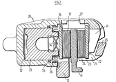
- Fig. 2 is a section on line II-II of Fig. 1;
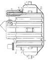
- Fig. 3 is a plan view of the brake shown in Figs. 1 and 2; and
- Fig. 4 is a perspective view of an element constituting two inserts for incorporation into the brake of Figs. 1 to 3.
- The brake shown in Fig. 1 incorporates a cast aluminium fixed
support 11. The fixed support incorporates a generally U-shaped portion, thebase 12 of which incorporates twomounting holes 13 and two upwardly extendinglimbs 14 of which carry wearresistant inserts 15.Inserts 15 provide wear resistant abutments for the ends ofsteel backing plate 16 offriction pad 17.Limbs 14 also carry, as an integral part of thefixed support casting 11,bridge members 18 which extend laterally from the upper outer ends oflimbs 14 outside a space provided for abrake disc 19 to the second major part of the fixed support which lies on the opposite side of the disc from thelimbs 14. This latter part of the fixed support comprisesabutment regions 21 carrying wearresistant inserts 22 for theback plate 23 of asecond brake pad 24. In order to provide a high degree of stiffness in conjunction with low weight and compactness, the twoabutment regions 21 are joined by abeam 25, also forming an integral part of the fixed support casting. - The brake also incorporates a
caliper 26 which is constituted primarily by an aluminium casting.Caliper 26 is guided for sliding movement in a direction parallel to the axis ofdisc 19 by means of twoguide pins 27 which are carried by screw threads in thefixed support 11. Flexible seals such as 28 prevent the ingress of dirt into the sliding surfaces. Only onepin 27 is shown, the other being housed within aboss 29 and having provision for differential thermal expansion between the two castings and for removal to allow friction pad replacement. - The
caliper 26 extends around the outer periphery of thedisc 19. At one side of the disc it has a supportingbracket 31 for engagement with theback plate 23 ofpad 24. At the opposite side of the disc, the caliper incorporates ahydraulic cylinder 32 which carries apiston 33 which in turn bears againstback plate 16 offriction pad 17 through aclip 34. The cylinder is provided with ahydraulic seal 35 and adust seal 36. The caliper is also provided with a hold-downclip 37 which engages the pad back plates and assists in holding them in position. - The two wear
resistant inserts resistant inserts arms location lug 41 formed by slitting and bending out a portion of the edge. Thearms fixed support 11 complete with bearing inserts, the complete element shown in Fig. 4 is first of all installed in a mould cavity within which the fixed support casting is to be poured. Because it is a relatively large element and the mould cavity has well spaced out clearly defined surfaces on which the twoinserts - For mass produced quantities, the casting technique employed will normally be die-casting, in which case the fixed support can be cast to sufficiently close tolerances to require little or no machining. For small production runs, sand casting may be more economic.
- Before the casting is ready for use as part of a brake, it is necessary to remove the
arms arms inserts arms disc 19 and across which thearms arms - In either case, the result is a fixed support for the brake-which has accurately defined wear resistant abutment surfaces for the brake pads.
- In use of the brake, it is typically installed in an upright rather than the horizontal position shown, that is with one of the
mounting holes 13 directly above the other. During brake applications caused by pressurizing thehydraulic cylinder 32, the pads move into firm engagement with the disc and rotation of the disc causes the pads to abut against one pair or wear resistant inserts, depending on the direction of disc rotation. The wear resistant inserts remain flat and accurately in position despite the loads applied to their abutment faces.by the pads and the transverse movement of the pads. This arrangement contributes to effective smooth brake operation over a long period of time. - Reference throughout this description and in the appended claims to a fixed support is intended to mean a support which is fixed in relation to the axis of rotation of a disc to be braked. The disc may for example be mounted on a stub axle carrier for an automobile wheel and thus be movable with the vehicle suspension.
Claims (8)
1. A disc brake comprising a cast metal fixed support (11), friction pads (17,24) arranged to be supported against brake reaction forces by abutment against the fixed support and means (26, 32, 33) for urging the pads into frictional engagement with a disc (19) between the pads characterised in that the fixed support is provided with cast in inserts (15, 22) of a material which is more wear resistant than the support itself against which inserts the pads bear for the transmission of brake reaction forces to the fixed support.
2. A disc brake as claimed in claim 1 characterised in that the fixed support (11) is made of a light metal and the wear resistant inserts (15, 22) are of steel.
3. A disc brake as claimed in claim 2 characterised in that the wear resistant inserts (15, 22) are of stainless steel.
4. A disc brake as claimed in any one of the preceding claims characterised in that each insert (15, 22) is a metal pressing having lugs (41) bent out from its surface to assist in holding the insert in position.
5. A disc brake as claimed in any preceding claim characterised in that two inserts (15, 22), one to each side of the disc, are initially formed as a single element (Figure 4) of the two inserts joined by a bridge (38, 39), wherein said element is cast into the fixed support with the bridge traversing a region required for passage of the disc, and wherein the bridge is removed after the casting is complete.
6. A disc brake as claimed in claim 5 characterised in that the bridge (38, 39) incorporates weakened regions at its junctions with the inserts and is removed by breaking away.
7. A disc brake as claimed in claim 5 characterised in that the bridge is removed by machining.
8. A method of providing two wear resistant inserts (15, 22) as friction pad abutments in a fixed support (11) for a disc brake including the steps of forming the two inserts and a bridge (Figure 4) as a single element, forming the fixed support (11) as a casting with the element cast into it and subsequently removing the bridge.
Applications Claiming Priority (2)
| Application Number | Priority Date | Filing Date | Title |
|---|---|---|---|
| GB8236707 | 1982-12-23 | ||
| GB8236707 | 1982-12-23 |
Publications (1)
| Publication Number | Publication Date |
|---|---|
| EP0113214A1 true EP0113214A1 (en) | 1984-07-11 |
Family
ID=10535217
Family Applications (1)
| Application Number | Title | Priority Date | Filing Date |
|---|---|---|---|
| EP83307539A Ceased EP0113214A1 (en) | 1982-12-23 | 1983-12-12 | Disc brakes |
Country Status (3)
| Country | Link |
|---|---|
| EP (1) | EP0113214A1 (en) |
| JP (1) | JPS59117924A (en) |
| GB (1) | GB2132713B (en) |
Cited By (4)
| Publication number | Priority date | Publication date | Assignee | Title |
|---|---|---|---|---|
| EP0316521A1 (en) * | 1987-11-14 | 1989-05-24 | Dr.Ing.h.c. F. Porsche Aktiengesellschaft | Brake device |
| WO1998057073A1 (en) * | 1997-06-12 | 1998-12-17 | Bosch Systemes De Freinage | Disk brake with prestressed guide tube |
| WO2005012754A1 (en) * | 2003-07-31 | 2005-02-10 | Ap Hydraulics Limited | Disc brake calipers |
| FR2861148A1 (en) * | 2003-10-20 | 2005-04-22 | Bosch Gmbh Robert | Disc brake caliper for motor vehicle e.g. car, has two pin guides arranged on both sides of bore at one end of main body, in disc rotation direction, where one guide is molded simultaneously with main body to form single unit |
Families Citing this family (7)
| Publication number | Priority date | Publication date | Assignee | Title |
|---|---|---|---|---|
| DE3803957A1 (en) * | 1988-02-10 | 1989-08-24 | Teves Gmbh Alfred | Spot-type disc brake |
| WO1996025608A1 (en) * | 1995-02-15 | 1996-08-22 | Itt Automotive Europe Gmbh | Lightweight disc brake |
| JP4495367B2 (en) * | 2001-08-13 | 2010-07-07 | 日信工業株式会社 | Vehicle disc brake |
| JP2005240904A (en) * | 2004-02-26 | 2005-09-08 | Nissin Kogyo Co Ltd | Disc brake for vehicle |
| JP2007177946A (en) * | 2005-12-28 | 2007-07-12 | Hitachi Ltd | Disc brake |
| DE102006002569A1 (en) * | 2006-01-18 | 2007-07-19 | Bpw Bergische Achsen Kg | disc brake |
| JP4647630B2 (en) * | 2007-02-16 | 2011-03-09 | 日立オートモティブシステムズ株式会社 | Disc brake |
Citations (3)
| Publication number | Priority date | Publication date | Assignee | Title |
|---|---|---|---|---|
| DE2950660A1 (en) * | 1979-12-15 | 1981-07-02 | Alfred Teves Gmbh, 6000 Frankfurt | Disc brake calliper assembly - has heavily-stressed portions made of material with high modulus of elasticity |
| GB2071240A (en) * | 1979-08-20 | 1981-09-16 | Tokico Ltd | Friction pad guide device for disc brake |
| GB2093935A (en) * | 1981-01-17 | 1982-09-08 | Nissin Kogyo Kk | Disc brake for vehicular use |
Family Cites Families (1)
| Publication number | Priority date | Publication date | Assignee | Title |
|---|---|---|---|---|
| GB1503237A (en) * | 1975-07-01 | 1978-03-08 | Girling Ltd | Disc brakes for vehicles |
-
1983
- 1983-12-12 EP EP83307539A patent/EP0113214A1/en not_active Ceased
- 1983-12-13 GB GB08333225A patent/GB2132713B/en not_active Expired
- 1983-12-22 JP JP24111383A patent/JPS59117924A/en active Pending
Patent Citations (3)
| Publication number | Priority date | Publication date | Assignee | Title |
|---|---|---|---|---|
| GB2071240A (en) * | 1979-08-20 | 1981-09-16 | Tokico Ltd | Friction pad guide device for disc brake |
| DE2950660A1 (en) * | 1979-12-15 | 1981-07-02 | Alfred Teves Gmbh, 6000 Frankfurt | Disc brake calliper assembly - has heavily-stressed portions made of material with high modulus of elasticity |
| GB2093935A (en) * | 1981-01-17 | 1982-09-08 | Nissin Kogyo Kk | Disc brake for vehicular use |
Cited By (6)
| Publication number | Priority date | Publication date | Assignee | Title |
|---|---|---|---|---|
| EP0316521A1 (en) * | 1987-11-14 | 1989-05-24 | Dr.Ing.h.c. F. Porsche Aktiengesellschaft | Brake device |
| US4875556A (en) * | 1987-11-14 | 1989-10-24 | Dr. Ing H.C.F. Porsche Aktiengesellschaft | Brake arrangement |
| WO1998057073A1 (en) * | 1997-06-12 | 1998-12-17 | Bosch Systemes De Freinage | Disk brake with prestressed guide tube |
| FR2764658A1 (en) * | 1997-06-12 | 1998-12-18 | Bosch Syst Freinage | DISC BRAKE WITH PRESTRESSED GUIDE TUBE |
| WO2005012754A1 (en) * | 2003-07-31 | 2005-02-10 | Ap Hydraulics Limited | Disc brake calipers |
| FR2861148A1 (en) * | 2003-10-20 | 2005-04-22 | Bosch Gmbh Robert | Disc brake caliper for motor vehicle e.g. car, has two pin guides arranged on both sides of bore at one end of main body, in disc rotation direction, where one guide is molded simultaneously with main body to form single unit |
Also Published As
| Publication number | Publication date |
|---|---|
| JPS59117924A (en) | 1984-07-07 |
| GB8333225D0 (en) | 1984-01-18 |
| GB2132713A (en) | 1984-07-11 |
| GB2132713B (en) | 1986-07-02 |
Similar Documents
| Publication | Publication Date | Title |
|---|---|---|
| US3391761A (en) | Vibration preventing means for a disc brake | |
| EP0851139B1 (en) | Disk brake | |
| EP1664570B1 (en) | Brake caliper for disc brake assembly and method and apparatus for producing same | |
| EP0113214A1 (en) | Disc brakes | |
| US4044864A (en) | Disc brake | |
| US6378666B1 (en) | Disc brake | |
| US6957724B2 (en) | Vehicle disk brake | |
| GB2034425A (en) | Disc brakes | |
| WO2016090086A1 (en) | Brake caliper for disc brake assembly and method and apparatus for producing same | |
| US3899052A (en) | Disc brake | |
| EP1151208B1 (en) | Hub support | |
| KR20070038172A (en) | Disk brake provided with a carrier of reduced size | |
| US5036932A (en) | Disc brake caliper housing | |
| US6367594B1 (en) | Disc brake pressure plate with abutment ears having laterally displaced sections | |
| CZ280168B6 (en) | Floating yoke and a brake shoe for disk brakes | |
| KR102210584B1 (en) | Partially lined automotive disc brakes with friction linings traction supported in frame-shaped holders | |
| KR100471914B1 (en) | Disc brake with slidable brake discs | |
| EP0049187B1 (en) | Disc brake | |
| EP0089750B1 (en) | Friction pad assembly for disc brakes | |
| EP1305538B1 (en) | Disck brake | |
| JPS6216508Y2 (en) | ||
| JP3665099B2 (en) | Control device returning device for caliper brake device for railway vehicle | |
| US4220225A (en) | Disc brake | |
| JP2590230Y2 (en) | Reaction type disc brake | |
| GB2342963A (en) | Friction material pad for a disc brake |
Legal Events
| Date | Code | Title | Description |
|---|---|---|---|
| PUAI | Public reference made under article 153(3) epc to a published international application that has entered the european phase |
Free format text: ORIGINAL CODE: 0009012 |
|
| AK | Designated contracting states |
Designated state(s): BE DE FR GB IT SE |
|
| 17P | Request for examination filed |
Effective date: 19841101 |
|
| 17Q | First examination report despatched |
Effective date: 19860409 |
|
| STAA | Information on the status of an ep patent application or granted ep patent |
Free format text: STATUS: THE APPLICATION HAS BEEN REFUSED |
|
| 18R | Application refused |
Effective date: 19880320 |
|
| RIN1 | Information on inventor provided before grant (corrected) |
Inventor name: BUNKER, KENNETH JAMES Inventor name: JOYNES, BRIAN |